Key Takeaways
- Core idea: Spring design turns a required force, travel, or torque into a spring type, material, geometry, stiffness, stress level, and fatigue life.
- Engineering use: Engineers use spring design to control motion, absorb energy, apply preload, return mechanisms, maintain contact force, and protect assemblies from shock or vibration.
- What controls it: Load range, deflection, wire diameter, mean coil diameter, active coils, material strength, solid height, end condition, and cycle life drive most spring design decisions.
- Practical check: A spring that has the right rate can still fail if stress, fatigue, buckling, coil bind, corrosion, temperature, or tolerance stack-up is ignored.
Table of Contents
Introduction
Spring design is the process of selecting a mechanical spring’s type, material, geometry, stiffness, load range, travel, stress level, fatigue life, and tolerances so it produces the required force or torque without permanent set, fatigue cracking, buckling, coil bind, or assembly interference.
Spring Design Workflow
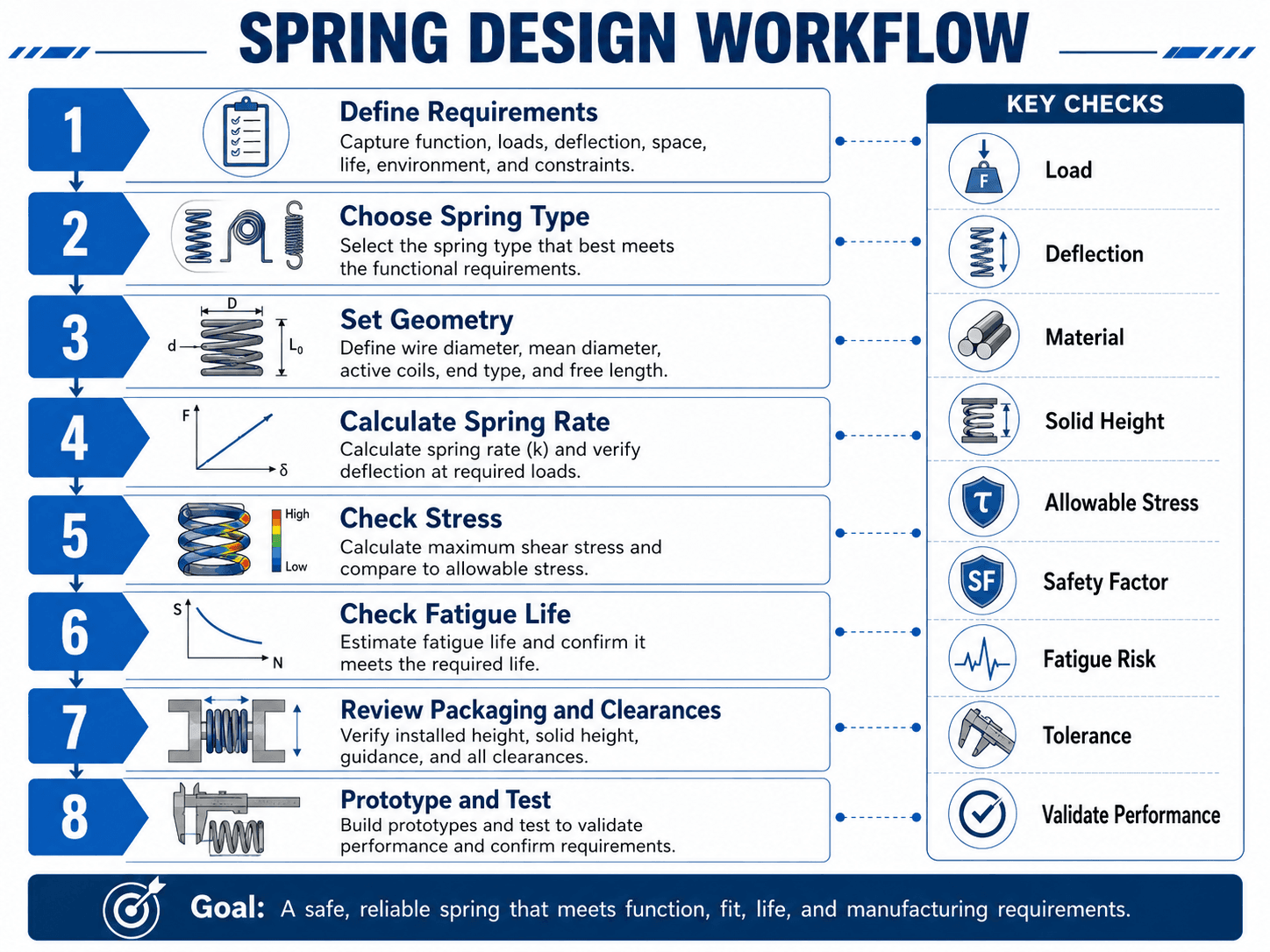
The most important idea is sequence: define the load and motion first, choose the spring type second, and only then calculate geometry, rate, stress, life, and manufacturability.
What Is Spring Design?
Spring design is the mechanical design process used to create or select a spring that stores and releases energy in a controlled way. The spring may resist compression, resist extension, create torque, hold preload, return a lever, isolate vibration, absorb shock, or maintain contact between parts.
In mechanical design, the spring is rarely an isolated part. It is part of an assembly with guides, seats, pins, stops, housing clearances, temperature exposure, corrosion risk, manufacturing tolerances, and expected life cycles. A good spring design therefore checks both the spring itself and the surrounding mechanism it must fit into.
A spring can match the desired force at one position and still be a poor design if it reaches solid height, rubs the housing, buckles, overstresses the wire, or loses load after repeated cycling.
How to Design a Spring Step by Step
A practical spring design calculation starts with the function, not the catalog. The designer first defines the force, travel, space, environment, and cycle life, then selects the spring type and checks geometry, rate, stress, fatigue, solid height, and tolerances.
Requirements → spring type → package space → material → geometry → spring rate → stress → fatigue → solid height and buckling → tolerances → prototype test.
| Step | What to define or check | Why it matters |
|---|---|---|
| 1. Define the function | Return motion, preload, contact force, shock absorption, torque, latch force, or energy storage | The function determines whether the spring should push, pull, rotate, or isolate motion |
| 2. Define loads and travel | Minimum force, maximum force, installed position, working deflection, and overtravel | These values determine spring rate, stress range, and solid-height margin |
| 3. Choose the spring type | Compression, extension, torsion, flat, or another spring form | The wrong spring type creates avoidable packaging, fatigue, and mounting problems |
| 4. Set the package limits | Maximum outside diameter, minimum inside diameter, free length, installed height, and clearance | Spring geometry must fit the assembly across tolerance extremes |
| 5. Select material and finish | Strength, corrosion resistance, temperature capability, fatigue behavior, and coating | Material controls allowable stress, relaxation, fatigue life, and environmental durability |
| 6. Calculate rate and geometry | Wire diameter, mean coil diameter, active coils, spring index, and free length | Geometry controls stiffness, stress, manufacturability, and solid height |
| 7. Check stress and fatigue | Maximum shear stress, corrected stress, cyclic stress range, and safety factor | A spring that works once can still fail after repeated service cycles |
| 8. Validate and specify | Load at height, tolerances, end type, prototype test, supplier drawing, and inspection method | The final spring must be manufacturable, inspectable, and repeatable in production |
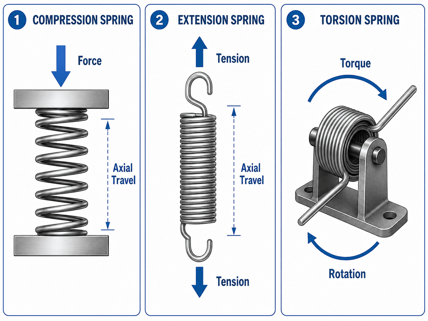
Compression, Extension, and Torsion Spring Design
The first major design decision is the type of spring. The spring type should follow the required motion and load direction. Compression springs resist shortening, extension springs resist being pulled longer, and torsion springs resist angular rotation.
| Spring type | Primary load | Common design concern | Typical use |
|---|---|---|---|
| Compression spring | Axial force that shortens the spring | Solid height, buckling, seat flatness, guide clearance, and maximum shear stress | Valves, buttons, suspension elements, clamps, plungers, and return mechanisms |
| Extension spring | Tension force that pulls the spring longer | Initial tension, hook stress, end-loop fatigue, attachment geometry, and overstretching | Counterbalances, linkages, screen doors, levers, and pull-return systems |
| Torsion spring | Torque and angular deflection about an axis | Leg orientation, mandrel clearance, coil direction, body diameter growth, and angular fatigue | Hinges, latches, clips, flaps, pedals, covers, and rotating return mechanisms |
Compression spring design
Compression spring design focuses on force versus compression, maximum shear stress, solid height, spring index, free length, and buckling. The designer must confirm the spring can compress through its full working travel without coil bind or lateral instability.
Extension spring design
Extension spring design focuses on tension load, extension travel, initial tension, body stress, hook stress, and attachment geometry. Hooks and loops are often the weak point because they introduce local bending and stress concentration outside the main coil body.
Torsion spring design
Torsion spring design focuses on torque, angular deflection, coil direction, mandrel clearance, leg orientation, and body diameter change during loading. The spring must be wound and installed so the applied load closes the coil in the intended direction rather than forcing unstable or damaging motion.
Spring Design Inputs Engineers Need First
Before calculating wire diameter or coil count, define the spring’s job in the assembly. The most common design mistake is calculating a spring rate before the load range, travel, space envelope, and life requirement are clear.
| Design input | Why it matters | Engineering implication |
|---|---|---|
| Required force or torque range | Defines what the spring must deliver at installed and working positions | Controls spring rate, preload, working stress, and whether a catalog spring can work |
| Deflection, extension, or rotation | Defines the working travel between minimum and maximum operating positions | Controls active coils, solid-height margin, angular travel, and fatigue stress range |
| Available package space | The spring must fit inside the housing, over a guide, or around a mandrel | Limits outer diameter, inner diameter, free length, leg geometry, and clearance |
| Cycle life | A spring used once has different requirements than one cycled millions of times | Determines whether fatigue, surface finish, shot peening, and stress reduction are critical |
| Environment | Temperature, moisture, chemicals, and corrosion can reduce spring performance | Affects material choice, coating, relaxation risk, and service life |
| Mounting and end conditions | The spring interacts with seats, hooks, pins, brackets, guides, and stops | Changes load alignment, stress concentration, wear, and tolerance stack-up |
The spring requirement is often hidden inside an assembly requirement. Instead of asking for “a 20 lb/in spring,” first ask what force the mechanism needs at the start and end of travel, what space is available, and how many cycles the product must survive.
Compression Spring Geometry and Terminology
Helical compression springs are often the easiest spring type to visualize, and the same geometry logic carries into many other spring designs. Wire diameter, coil diameter, active coils, free length, and solid height strongly affect stiffness, stress, manufacturability, and assembly clearance.
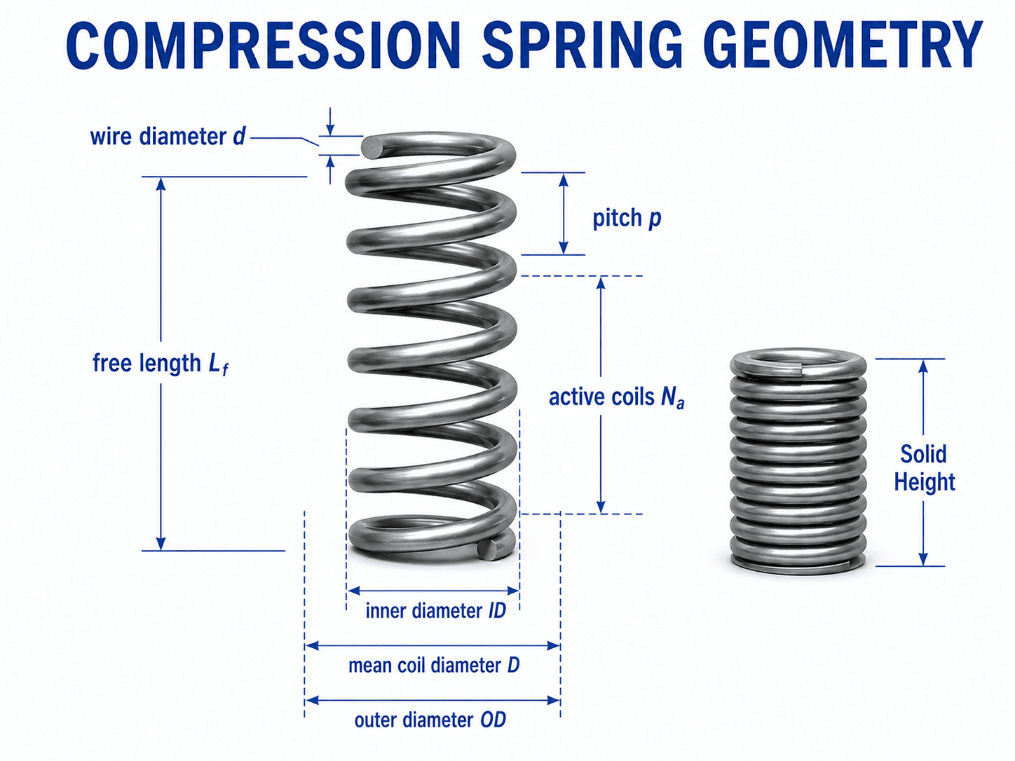
Use the geometry diagram while reading the spring design formulas below. The same symbols appear in rate, spring index, stress, and solid-height checks.
- \(d\) Wire diameter. Larger wire usually increases stiffness and reduces stress, but it also increases solid height and space requirements.
- \(D\) Mean coil diameter. This is the average coil diameter used in common helical spring equations.
- \(N_a\) Active coils. More active coils generally reduce spring rate and increase deflection capacity.
- \(C\) Spring index, where \(C = D/d\). It is a manufacturability and stress indicator for helical springs.
- \(L_f\) Free length. The unloaded spring length before installation or compression.
- \(L_s\) Solid height. The approximate length of a compression spring when the coils are fully closed.
Spring Design Formulas and Calculations
The most useful spring design formulas connect load, deflection, stiffness, stress, and geometry. For many first-pass compression spring checks, spring rate, spring index, corrected shear stress, and solid-height margin are the most important calculations.
Spring rate calculation
For a linear spring, spring rate is the change in force divided by the change in deflection.
Here, \(k\) is spring rate, \(\Delta F\) is the change in load, and \(\Delta x\) is the change in deflection. Common units include N/mm, N/m, lb/in, and lbf/in.
Compression spring rate estimate
For a round-wire helical compression spring, a common first-pass spring rate estimate is:
This equation shows why wire diameter has such a strong effect. Because \(d\) is raised to the fourth power, a small wire diameter change can create a large change in stiffness and stress.
Spring index
Spring index is a practical geometry check:
Very low spring index values can be difficult to manufacture and can raise stress concentration. Very high spring index values may make the spring slender, flexible, and more sensitive to buckling or tangling.
Wahl factor and corrected shear stress
The Wahl factor is commonly used to correct helical spring stress for curvature and direct shear effects. It is especially important when checking maximum working stress in a compression spring.
In this expression, \(\tau_{max}\) is the corrected maximum shear stress, \(K_w\) is the Wahl factor, \(F\) is axial force, \(D\) is mean coil diameter, and \(d\) is wire diameter.
Solid height estimate
Solid height is the approximate compressed length when the coils are closed. A simple first-pass estimate for many compression springs is:
Here, \(L_s\) is solid height, \(N_t\) is total coils, and \(d\) is wire diameter. Actual solid height depends on end type, grinding, manufacturing method, and spring details, so it should be verified against supplier data or inspection requirements.
- \(k\) Spring rate or stiffness, commonly in N/mm or lb/in.
- \(G\) Shear modulus of the spring material, commonly in MPa, GPa, or psi.
- \(F\) Axial load for compression or extension springs.
- \(x\) Deflection from the reference length or installed position.
- \(D\) Mean coil diameter, measured to the centerline of the wire.
- \(K_w\) Wahl correction factor used to adjust helical spring shear stress.
- \(\tau_{max}\) Corrected maximum shear stress in the spring wire.
For a deeper formula-first review of the basic force-deflection relationship, see the Turn2Engineering page on Hooke’s Law.
Spring Material Selection
Spring material selection controls strength, stiffness, corrosion resistance, temperature capability, cost, fatigue behavior, and relaxation. The best spring material is not always the strongest material; it is the material that survives the load, environment, cycle life, and manufacturing process at an acceptable cost.
| Spring material family | Why it is used | Design caution |
|---|---|---|
| Music wire | High strength and common for many general-purpose springs | Not ideal for corrosive or high-temperature environments without additional protection |
| Stainless spring wire | Improved corrosion resistance for moisture, outdoor exposure, or clean applications | Strength and fatigue behavior may differ from carbon spring wire, so allowable stress must be checked |
| Chrome silicon | Useful for higher stress, shock loading, and demanding mechanical applications | Cost, availability, processing, and design stress limits should be evaluated early |
| Chrome vanadium | Used where toughness and fatigue resistance are important | Material processing and heat treatment quality affect final performance |
| Phosphor bronze or beryllium copper | Useful where electrical conductivity, corrosion resistance, or nonmagnetic behavior matters | Material cost and lower strength compared with some steels may control the design |
If the spring will see high temperature, corrosive media, washdown, outdoor exposure, electrical current, or millions of cycles, material selection should happen before final geometry is locked in.
Stress, Fatigue, and Life Checks
Spring design is often controlled by stress and fatigue rather than by stiffness alone. A spring can have the correct force-deflection curve during a bench test but still fail later if cyclic stress, stress concentration, surface condition, or corrosion is not addressed.
Static stress check
Static stress checks compare the maximum working stress to a suitable allowable stress for the material, processing, and application. For helical springs, stress correction is important because the curved wire experiences more than simple torsion.
Fatigue check
Spring fatigue design matters when the spring cycles repeatedly between two load positions. The working stress range, mean stress, surface finish, shot peening, corrosion, temperature, and end geometry all influence life. Extension spring hooks and torsion spring legs often need special attention because local bending and stress concentration can control failure.
Load at height versus spring rate
In production spring design, load at height is often more useful than rate alone. A drawing can specify that the spring must produce a defined load at a defined compressed height, which is easier to inspect and closer to the assembly function than a theoretical rate value by itself.
Do not treat a static load check as a fatigue-life check. A spring that survives one full compression can still crack after repeated cycles if the stress range is too high or if the end detail creates a stress concentration.
For broader component-level checking, the related Turn2Engineering guide on Stress Analysis explains how loads, geometry, material limits, and failure risk are evaluated in mechanical design.
Worked Spring Design Example
Suppose a small plunger needs a compression spring that provides 20 N at the installed position and 50 N at the maximum compressed position. The spring compresses an additional 15 mm between those two positions.
Calculate the required spring rate
The required spring rate calculation is the load change divided by the working deflection:
This means the spring must gain about 2 N of load for each millimeter of additional compression across the working range.
Interpret the result
The 2.0 N/mm rate is only the first requirement. The design still needs enough preload at installation, enough travel before solid height, acceptable maximum stress at 50 N, enough clearance around the spring, a suitable material for the environment, and fatigue life appropriate for the number of cycles.
If the assembly only has 16 mm of total available compression but the spring needs 15 mm of working travel, there may be little room left for solid-height margin, tolerances, wear, or overtravel. That design should be reviewed before release.
For simple force-deflection checks, the Spring Constant Calculator can help verify the basic relationship between force, deflection, and spring rate.
Spring Design Requirements Sheet
A spring requirements sheet prevents the design from becoming a rate-only problem. It captures the functional, geometric, material, environmental, inspection, and life requirements that control whether the spring will work in the final assembly.
| Requirement | What to specify | Why it matters |
|---|---|---|
| Spring type | Compression, extension, torsion, flat, constant force, or custom form | Prevents using the wrong load model or motion direction |
| Load at position | Force or torque at installed, working, and maximum positions | Defines actual assembly performance and inspection points |
| Travel | Compression distance, extension distance, or angular rotation | Controls stress range, solid height, fatigue, and package clearance |
| Package envelope | Maximum OD, minimum ID, free length, installed height, mandrel size, or bracket space | Ensures the spring fits at all operating and tolerance conditions |
| Material and finish | Spring wire material, plating, coating, passivation, or corrosion protection | Controls strength, fatigue, corrosion resistance, and temperature behavior |
| Cycle life | Expected number of cycles and operating frequency | Determines whether fatigue design controls the spring |
| End configuration | Ground ends, closed ends, hooks, loops, torsion legs, or custom forms | Controls load transfer, alignment, local stress, and installation quality |
| Tolerances | Load, rate, free length, OD, ID, squareness, angular leg position, or hook geometry | Prevents production variation from breaking assembly performance |
Senior Engineer Spring Design Review Checklist
A good spring review checks whether the design works as a real part in a real assembly, not just whether a formula returns the expected rate. Use this checklist before releasing a custom spring, choosing a catalog spring, or approving a supplier drawing.
Confirm the function first, then the spring type, then the geometry, then the rate, then stress and fatigue, then assembly clearances, then prototype test results. If one step fails, revise the design before moving forward.
| Review check | What to look for | Why it matters |
|---|---|---|
| Load at installed and working positions | Minimum and maximum force or torque are defined at actual assembly positions | Prevents designing only for a single force value while missing the working range |
| Solid-height margin | Maximum compression does not drive the spring into coil bind, including tolerances and overtravel | Coil bind can spike stress, damage parts, and permanently set the spring |
| Spring index | Mean coil diameter and wire diameter produce a practical manufacturing ratio | Extreme spring index values can create manufacturing problems, stress issues, or instability |
| Stress and fatigue | Maximum stress and cyclic stress range are acceptable for material, finish, and life | Fatigue failure is one of the most common reasons springs fail after initial testing |
| Guidance and buckling | Long compression springs are guided or proportioned to avoid lateral instability | Buckling changes the load path, increases rubbing, and can damage the spring or housing |
| End details | Hooks, loops, ground ends, legs, and seats match the load path and assembly hardware | Spring ends often control local stress, alignment, wear, and installation quality |
| Environment and material | Temperature, moisture, chemicals, and corrosion exposure are reflected in material and finish | A spring that works in the lab may lose load or corrode in the field if the environment is ignored |
| Supplier specification | Drawing or purchase specification includes type, material, dimensions, rate, loads at height, ends, finish, and tolerances | Incomplete specifications lead to springs that are technically similar but functionally wrong |
How to Specify a Spring for Manufacturing
A spring specification should describe the part well enough that a supplier can manufacture it and quality control can inspect it. For many production designs, specifying load at height is more useful than relying on free length and rate alone.
| Specification item | What to include | Reason to include it |
|---|---|---|
| Spring type | Compression, extension, torsion, or other spring form | Defines the basic load and motion model |
| Material and finish | Wire material, coating, passivation, plating, or finish requirement | Controls strength, corrosion resistance, appearance, and environmental durability |
| Geometry | Wire diameter, OD, ID, mean diameter, free length, active coils, total coils, and pitch where needed | Defines fit, rate, solid height, manufacturability, and inspection geometry |
| End type | Closed and ground ends, hooks, loops, machine hooks, torsion legs, or custom ends | Controls seating, attachment, stress concentration, and assembly fit |
| Load at height | Required load at installed height and working height | Directly connects spring inspection to the actual assembly function |
| Spring rate | Nominal rate and tolerance if rate is a controlled characteristic | Controls force change over travel but should be paired with load-at-height checks |
| Solid height or maximum travel | Minimum margin before coil bind and any overtravel allowance | Prevents permanent set, high stress, and assembly damage |
| Direction and orientation | Hand of wind, torsion leg orientation, hook orientation, and installed position | Prevents reversed installation or incorrect torque direction |
| Inspection and testing | Load test, dimensional inspection, cycle test, surface finish, or sample approval | Creates measurable acceptance criteria for production parts |
If the drawing does not tell the supplier where the spring load must be measured, the delivered spring may meet dimensional requirements but still fail the mechanism’s force requirement.
Common Spring Failure Modes and Design Mistakes
Most spring problems come from treating the spring as a simple elastic symbol rather than a manufactured mechanical component. The common failures are predictable if the design is reviewed against the actual load path, assembly constraints, environment, and life requirement.
| Failure mode or mistake | What causes it | Practical design check |
|---|---|---|
| Permanent set | Stress exceeds the material’s elastic capability or the spring is compressed too far | Check maximum working stress, solid-height margin, and load after cycling |
| Fatigue cracking | Repeated stress range is too high, especially at hooks, legs, or surface defects | Check cyclic stress, surface condition, shot peening need, and local end stress |
| Coil bind | The spring reaches solid height before the mechanism reaches its stop | Confirm maximum deflection with tolerance stack-up and overtravel allowance |
| Buckling | A long compression spring deflects sideways under axial load | Use a guide rod, reduce slenderness, increase diameter, or redesign the package |
| Corrosion-related failure | Material or coating is not suitable for moisture, chemicals, or outdoor exposure | Select a corrosion-resistant material or finish and validate field exposure |
| Wrong force at assembly | Free length, rate tolerance, installed height, or seat geometry is not controlled | Specify load at height and check tolerance stack-up across the assembly |
| Hook or leg failure | Extension spring hooks or torsion spring legs see local bending and stress concentration | Review end geometry separately from the main coil body |
The biggest spring design mistake is approving the rate while ignoring the maximum operating position. The end of travel is where solid height, stress, buckling, and permanent set usually become critical.
Engineering Judgment and Field Reality
Real spring behavior includes manufacturing variation, friction, seating effects, temperature, corrosion, wear, and assembly misalignment. A spring may test correctly on a bench fixture but behave differently once installed in a mechanism with off-axis loading, rough seats, guide clearance, or tolerance variation.
Engineers often specify load at one or more working heights instead of only specifying free length and rate. Load-at-height requirements are easier to verify with inspection equipment and better represent how the spring performs in the assembly.
For production parts, spring rate is not enough. Ask whether the spring produces the correct load after installation, after cycling, at temperature, at tolerance extremes, and after realistic environmental exposure.
When This Breaks Down
Simplified spring design methods are useful for first-pass sizing, but they stop being reliable when the spring is highly nonlinear, dynamically loaded, poorly guided, exposed to harsh environments, or controlled by local end stresses rather than simple coil behavior.
- Large deflections can make the spring response nonlinear and can invalidate simple force-deflection assumptions.
- Dynamic loading, impact, vibration, surge, or resonance may require testing or more advanced analysis.
- High temperature can reduce load over time through relaxation or creep-like behavior in the spring material.
- Corrosion and surface damage can reduce fatigue life even when the nominal stress calculation looks acceptable.
- Extension spring hooks and torsion spring legs may fail before the main coil body if local stress is not reviewed.
- Assembly tolerance stack-up can change installed height, preload, working travel, and available clearance.
When the spring is safety-critical, highly cycled, exposed to harsh environments, or difficult to inspect after installation, prototype testing and supplier review should be part of the design process.
Engineering References and Design Guidance
Spring design often uses a mix of mechanics equations, material data, supplier manufacturing rules, and application-specific testing. For a deeper industry reference, the Spring Manufacturers Institute provides a dedicated handbook focused on spring design and specification.
- Spring Manufacturers Institute: Handbook of Spring Design covers compression, extension, torsion, and flat spring design guidance, calculation examples, and specification context for manufactured springs.
- Project-specific criteria: Product safety requirements, owner specifications, environmental exposure, manufacturing process limits, and qualification testing may control the final design.
- Engineering use: Engineers typically use references like this to check equations, allowable design assumptions, terminology, supplier communication, and spring specification details.
Frequently Asked Questions
Spring design is the process of selecting a spring type, material, geometry, stiffness, load range, travel, stress level, fatigue life, and manufacturing tolerance so the spring performs its function safely over the required service life.
You need the required load range, deflection or rotation, available package space, installed length, required life cycles, operating environment, material constraints, safety factor target, and how the spring will be mounted or guided.
The spring rate relationship is usually the starting point because it connects force and deflection, but a complete design also checks stress, fatigue, solid height, buckling, material limits, and manufacturing tolerances.
The Wahl factor is a stress correction factor used for helical springs. It adjusts calculated shear stress for wire curvature and direct shear effects so the designer does not underestimate maximum working stress.
Springs commonly fail from fatigue, overstress, coil bind, buckling, corrosion, wrong material selection, poor end design, excessive temperature, or ignoring tolerance stack-up between the spring and the surrounding assembly.
Summary and Next Steps
Spring design is the engineering process of turning force, travel, torque, packaging, material, life, and manufacturing requirements into a spring that works reliably in an actual assembly. The right design balances stiffness, stress, fatigue, solid-height margin, guidance, end conditions, and environment.
The most useful workflow is to define requirements first, select the spring type from the motion, size the geometry, calculate rate, check stress and fatigue, review package clearances, specify production requirements, and validate the result through prototype testing or supplier confirmation.
Where to go next
Continue your learning path with related Turn2Engineering resources.
-
Mechanical Design
Explore the broader mechanical design hub for components, materials, tolerances, stress analysis, prototyping, and manufacturability.
-
Spring Constant Calculator
Calculate spring constant from force and deflection when checking a simple linear spring relationship.
-
Hooke’s Law
Review the core elastic force-deflection relationship behind many first-pass spring calculations.