Key Takeaways
- Main formula: Bending stress is commonly written as \( \sigma = \dfrac{My}{I} \), with maximum bending stress written as \( \sigma_{max} = \dfrac{Mc}{I} = \dfrac{M}{S} \).
- Key inputs: You need the internal bending moment \(M\), distance from the neutral axis \(y\) or \(c\), and second moment of area \(I\).
- Best used when: The member behaves elastically, plane sections remain plane, and the section properties are taken about the correct neutral axis.
- Practical check: Keep moment and section-property units consistent; \(N \cdot mm\), \(mm\), and \(mm^4\) give stress in \(N/mm^2\), or MPa.
Table of Contents
Introduction
The bending stress formula calculates the normal stress caused by a bending moment in a beam or flexural member. In its common elastic form, \( \sigma = \dfrac{My}{I} \), stress increases with bending moment and distance from the neutral axis, and decreases as the cross-section moment of inertia increases.
Use \( \sigma = \dfrac{My}{I} \) to calculate bending stress at a point in a beam cross-section. Use \( \sigma_{max} = \dfrac{Mc}{I} \) or \( \sigma_{max} = \dfrac{M}{S} \) for maximum stress at the outer fiber.
Bending Stress Distribution in a Beam
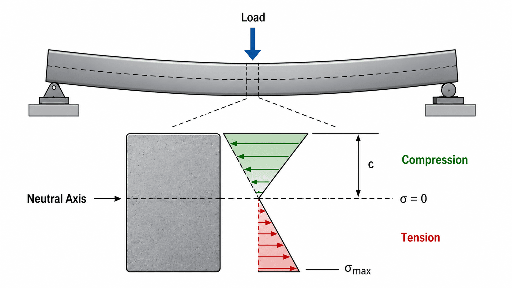
Notice that the stress distribution is not uniform. For a typical sagging beam, the top fibers are in compression and the bottom fibers are in tension. The formula uses distance from the neutral axis because stress grows as that distance increases.
What Is the Bending Stress Formula?
The bending stress formula is the elastic flexure equation used to estimate normal stress in a beam cross-section from internal bending moment. It connects the external loading problem to the internal stress state by combining \(M\), \(y\), and \(I\).
Engineers typically use it after finding the bending moment at a critical section. The largest stress usually occurs where the bending moment is largest and where the cross-section fiber is farthest from the neutral axis.
The Bending Stress Formula
The standard elastic flexure formula gives the normal bending stress at a point in the cross-section. It is used after the internal bending moment at the section has been found from statics, a shear and moment diagram, or a structural analysis model.
- \( \sigma \) Normal bending stress at a distance \(y\) from the neutral axis.
- \( M \) Internal bending moment at the cross-section being checked.
- \( y \) Distance from the neutral axis to the point where stress is being calculated.
- \( I \) Second moment of area about the bending axis.
The equation says that stress is larger where the bending moment is larger, where the point is farther from the neutral axis, or where the section has a smaller second moment of area. At the neutral axis, \(y = 0\), so the bending stress is zero.
Maximum Bending Stress Formula
For design checks, engineers often care about the maximum bending stress at the farthest fiber from the neutral axis. In that case, \(c\) replaces \(y\).
The maximum bending stress occurs at the extreme fiber, where \(c\) is the maximum distance from the neutral axis to the top or bottom surface of the section.
Section Modulus Form
The same maximum-stress relationship is often written using elastic section modulus.
The section modulus form is convenient in beam design because many steel, timber, aluminum, and manufactured section tables list \(S\) directly. Some references use \(Z\) or \(W\) instead of \(S\) for elastic section modulus, so always confirm the notation. Do not confuse elastic section modulus with plastic section modulus, which is used for plastic capacity checks.
Why Some References Use a Negative Sign
Some mechanics references write the signed flexure formula as \( \sigma_x = -My/I \). The negative sign is a sign-convention detail that identifies which side of the neutral axis is in compression or tension for a chosen positive moment and coordinate direction.
For stress magnitude checks, \( \sigma = My/I \) and \( \sigma_{max} = Mc/I \) are commonly used. For sign-sensitive analysis, define the positive \(y\)-axis, moment sign convention, and whether positive stress means tension or compression before interpreting the result.
Bending Stress Formula Variables and Units
Use one consistent unit system throughout the formula. The most common mistake is mixing bending moment units with section-property units, such as using \(kN \cdot m\) with \(mm^4\) without converting the moment to \(N \cdot mm\).
- \( \sigma \) Normal bending stress at the point being checked.
- \( M \) Internal bending moment at the cross-section being evaluated.
- \( y, c \) Distance from the neutral axis to the point of interest; \(c\) is used for the farthest extreme fiber.
- \( I \) Second moment of area about the bending axis, sometimes loosely called area moment of inertia. It is not mass moment of inertia.
- \( S \) Elastic section modulus, equal to \(I/c\), used in the alternate form \( \sigma_{max} = M/S \).
| Symbol | Meaning | SI units | US customary units | Practical note |
|---|---|---|---|---|
| \( \sigma \) | Bending stress | Pa, MPa, or \(N/mm^2\) | psi or ksi | Tension and compression signs depend on the sign convention and which side of the neutral axis is checked. |
| \( M \) | Internal bending moment | \(N \cdot m\), \(kN \cdot m\), or \(N \cdot mm\) | \(lb \cdot in\), \(kip \cdot in\), or \(kip \cdot ft\) | Convert to match the length units used for \(y\), \(c\), and \(I\). |
| \( y \) | Distance from neutral axis to the point checked | m or mm | in or ft | Use \(y=0\) at the neutral axis; use positive or negative values consistently. |
| \( c \) | Distance from neutral axis to the extreme fiber | m or mm | in or ft | For unsymmetrical sections, top and bottom \(c\) values may be different. |
| \( I \) | Second moment of area about the bending axis | \(m^4\) or \(mm^4\) | \(in^4\) | Use the axis that matches the direction of bending, not a random tabulated value. |
| \( S \) | Elastic section modulus | \(m^3\) or \(mm^3\) | \(in^3\) | Used for maximum stress only; \(S = I/c\). Some references use \(Z\) or \(W\). |
If \(I\) is in \(mm^4\) and \(c\) is in \(mm\), convert the bending moment to \(N \cdot mm\). For example, \(1 \; kN \cdot m = 1{,}000{,}000 \; N \cdot mm\).
Quick Reference for Bending Stress Formula
Use this quick reference when checking whether the bending stress formula is the right tool for a beam or member stress calculation.
| Item | What to know |
|---|---|
| What it calculates | Normal stress caused by bending at a point in a cross-section. |
| Required inputs | Bending moment \(M\), distance from neutral axis \(y\) or \(c\), and second moment of area \(I\). |
| Maximum stress form | \( \sigma_{max} = Mc/I = M/S \). |
| Common units | \(N \cdot mm\), \(mm\), \(mm^4\), and MPa in SI-style structural calculations; \(kip \cdot in\), \(in\), \(in^4\), and ksi in US customary calculations. |
| Best used when | The beam is elastic, prismatic near the checked section, and the neutral axis and section properties are known. |
| Do not use when | The member has yielded, the section is cracked or composite without transformed properties, local buckling controls, or shear deformation dominates. |
| Common mistake | Using the wrong moment of inertia axis or mixing \(kN \cdot m\) with \(mm^4\) without converting units. |
Bending Stress Formula for Rectangular Sections
For a rectangular cross-section with width \(b\) and total depth \(d\), the second moment of area about the centroidal bending axis is:
For a symmetric rectangular section, the extreme-fiber distance is:
Substituting \(I = bd^3/12\) and \(c=d/2\) into \( \sigma_{max} = Mc/I \) gives the rectangular beam shortcut:
For a rectangular section, bending stress decreases with the square of depth in the shortcut formula. This is why increasing beam depth is usually much more effective than simply increasing width.
How to Use the Bending Stress Formula Correctly
A reliable bending stress calculation starts before the formula. The formula only works if the moment demand and section properties are correct.
- Draw or obtain the beam loading and support conditions.
- Find support reactions using statics or structural analysis.
- Build the shear and moment diagram.
- Identify the critical bending moment \(M\), usually the maximum absolute moment.
- Choose the correct bending axis for the cross-section.
- Find \(I\), \(c\), or \(S\) for that axis.
- Compute \( \sigma_{max} = Mc/I \) or \( \sigma_{max} = M/S \).
- Compare the result against the appropriate allowable or design stress.
- Check shear, deflection, buckling, connections, and code requirements separately.
If the moment \(M\) came from the wrong location or the wrong load combination, the bending stress result will still look mathematically correct but will not represent the governing design condition.
How to Rearrange the Bending Stress Formula
The most useful rearrangements solve for required section modulus, required moment of inertia, or allowable bending moment. These forms are helpful when sizing a beam rather than simply checking a known section.
This form estimates the required elastic section modulus when an allowable stress or design stress limit is known.
This form estimates the required second moment of area when the extreme-fiber distance \(c\) is known or assumed.
The section modulus form should produce units of volume: \(S = M/\sigma\). In SI-style units, \(N \cdot mm\) divided by \(N/mm^2\) gives \(mm^3\).
Worked Example
Suppose a beam section has a maximum internal bending moment of \(6.0 \; kN \cdot m\). The neutral axis is at mid-depth, the farthest fiber is \(150 \; mm\) from the neutral axis, and the second moment of area about the bending axis is \(8.50 \times 10^6 \; mm^4\). Estimate the maximum elastic bending stress.
The numerator is \(9.00 \times 10^8 \; N \cdot mm^2\). Dividing by \(8.50 \times 10^6 \; mm^4\) gives stress units of \(N/mm^2\), which is equivalent to MPa.
Check the Same Example Using Section Modulus
The same result can be checked using \(S = I/c\).
A result near \(106 \; MPa\) is plausible for a moderate steel beam stress check, but whether it is acceptable depends on material strength, load combinations, safety factors, serviceability limits, and the applicable design method.
How Section Geometry Changes Bending Stress
The formula explains why two beams under the same load can have very different bending stresses. If \(M\) stays the same, increasing \(I\) or section modulus \(S\) reduces the calculated stress.
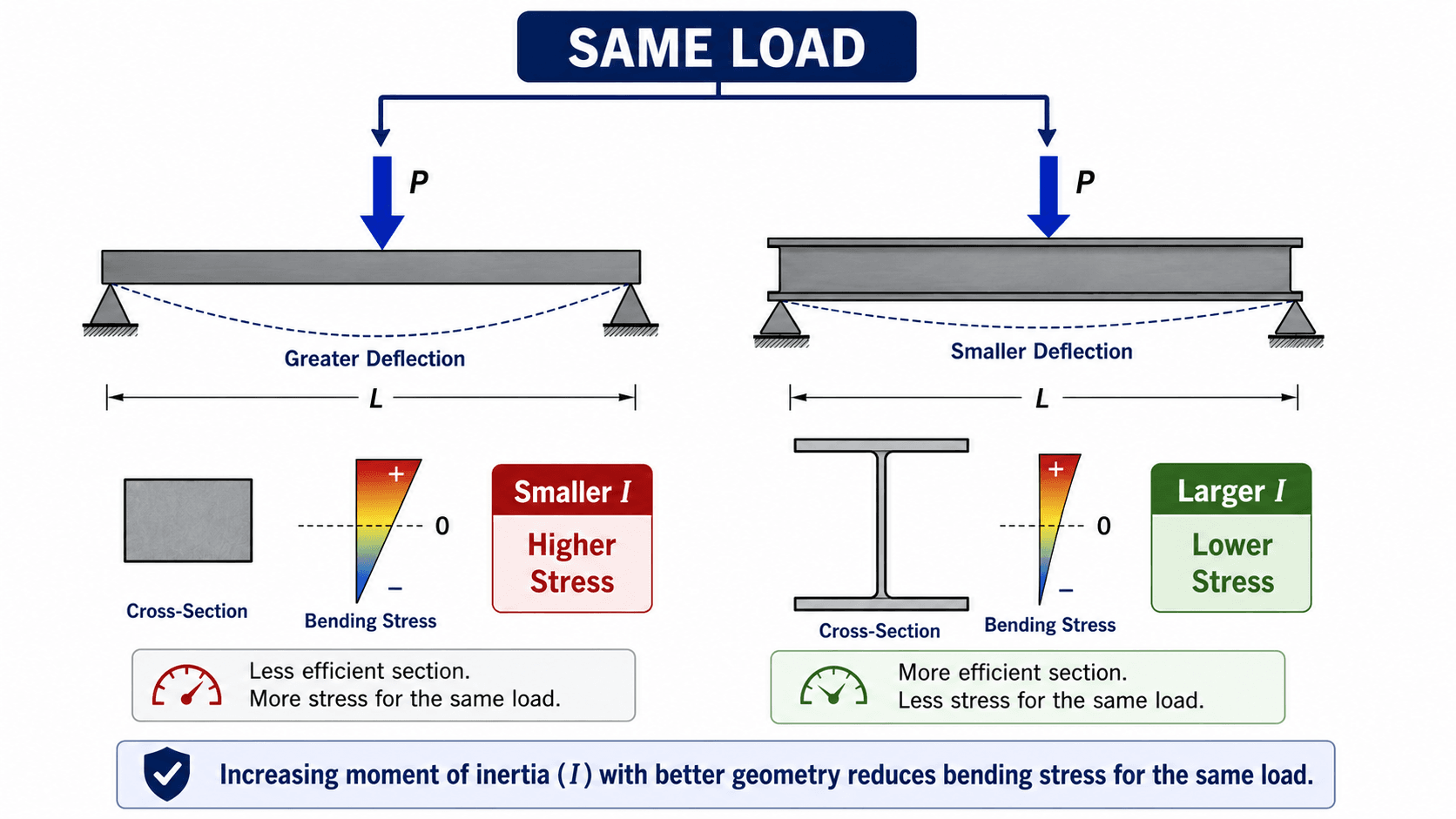
The important idea is not just “more material.” It is where the material is located relative to the neutral axis. Material farther from the neutral axis increases \(I\) more effectively, which is why deeper sections and I-shaped sections are efficient in bending.
Where Engineers Use the Bending Stress Formula
Engineers use the bending stress formula as a fast stress check when bending moment and cross-section properties are known. It is most useful as a mechanics-of-materials calculation before moving into code-specific member design.
- Beam sizing: estimate maximum bending stress from a moment diagram and compare it with an allowable or factored stress limit.
- Section selection: compare rectangular, channel, tube, or I-shaped sections by checking how \(I\) and \(S\) affect stress.
- Failure investigation: identify whether high bending moment and low section modulus could explain cracking, yielding, or overstress.
- Machine and frame members: check shafts, brackets, arms, and structural components where bending stress may control.
Assumptions and Limitations
The bending stress formula is powerful because it is simple, but it is not a complete beam design method. It gives elastic normal stress from bending under a specific set of mechanics assumptions.
- 1 The material is behaving linearly elastically, so stress is proportional to strain.
- 2 Plane sections remain plane after bending, which leads to a linear strain and stress distribution.
- 3 The cross-section properties are correct for the bending axis being checked.
- 4 The member is not controlled by local buckling, lateral-torsional buckling, connection effects, or material nonlinear behavior.
- 5 Composite, cracked, or multi-material sections use appropriate transformed properties or code-specific methods.
Elastic vs Plastic Bending
The formula \( \sigma = My/I \) is an elastic bending relationship. Once yielding spreads through the section, the stress distribution is no longer the same linear elastic triangle.
| Condition | Stress model | Use \( \sigma = My/I \)? |
|---|---|---|
| Elastic bending | Linear stress distribution through the section depth | Yes, when assumptions are satisfied |
| First yield | Extreme fiber reaches yield stress | Use as an elastic limit check, not as a plastic capacity method |
| Plastic bending | Nonlinear or plastic stress distribution | No; use plastic analysis or the applicable design code method |
| Deep, curved, composite, or cracked members | Stress distribution may not match simple elastic beam theory | Use a more appropriate model or transformed-section approach |
When This Breaks Down
The formula becomes less reliable when the section has yielded, when concrete cracks without transformed-section analysis, when composite action is partial, when thin elements buckle locally, or when the member requires code-based strength reduction, load factors, or stability checks.
For unsymmetrical sections or combined bending about two axes, check both extreme fibers and use the appropriate biaxial bending relationship rather than assuming one simple \(Mc/I\) value controls everything.
Do not treat \( \sigma = Mc/I \) as the final design approval for a structural member. It is a stress calculation. Real design may also require shear, deflection, buckling, bearing, connection, fatigue, and code-specific checks.
Common Mistakes and Engineering Checks
Most bending stress errors come from using the right-looking formula with the wrong section property, distance, moment unit, or sign convention.
| Mistake | Why it causes error | Engineering check |
|---|---|---|
| Using the wrong \(I\) axis | Bending about the strong axis and weak axis can produce very different stresses. | Match the moment direction to the correct cross-section axis and tabulated \(I\). |
| Forgetting to convert \(kN \cdot m\) to \(N \cdot mm\) | The result can be off by factors of \(10^3\) or \(10^6\). | Write the units in the substitution line before calculating. |
| Using total beam depth instead of \(c\) | The formula needs distance from the neutral axis, not the full section depth. | For a symmetric rectangular section, \(c = d/2\), not \(d\). |
| Confusing second moment of area with mass moment of inertia | They are different properties with different units and physical meaning. | For bending stress, \(I\) should have length-to-the-fourth units such as \(mm^4\) or \(in^4\). |
| Ignoring unsymmetrical sections | Top and bottom extreme fibers may have different \(c\) values and different stress magnitudes. | Check both sides of the neutral axis when the section is not symmetric. |
| Using elastic stress after yielding | The linear stress distribution no longer represents the actual plastic stress state. | Use an appropriate plastic, nonlinear, or code-based method when yielding is expected. |
The most common publishing and homework error is writing \( \sigma = Mc/I \) correctly but substituting inconsistent units. The formula is not unitless; the dimensions must reduce to force per area.
Bending Stress vs Shear Stress
Bending stress and shear stress are both beam stress checks, but they are not the same calculation. Bending stress is a normal stress caused by bending moment, while shear stress is a tangential stress caused by shear force.
| Check | Primary demand | Stress direction | Where it is often critical |
|---|---|---|---|
| Bending stress | Bending moment \(M\) | Normal stress, tension or compression | Outer fibers farthest from the neutral axis |
| Shear stress | Shear force \(V\) | Tangential stress along the section | Often near the neutral axis for common beam sections |
| Deflection | Load, span, stiffness, and boundary conditions | Serviceability movement, not stress | Midspan or other maximum displacement locations |
A beam may pass bending stress but still fail a shear, deflection, buckling, connection, or serviceability check. For this reason, bending stress should be treated as one part of a broader member evaluation.
Bending Stress Formula vs Related Equations
Bending stress is often used with shear, deflection, and moment equations. These equations answer different questions, so they should not be substituted for one another.
| Equation or method | Best used for | Main assumption | Common limitation |
|---|---|---|---|
| Bending stress formula | Normal stress from bending moment at a cross-section | Elastic flexure and correct section properties | Does not check shear, buckling, deflection, or code strength by itself |
| Shear stress equation | Stress caused by shear force acting parallel to a resisting area | Depends on whether average or beam shear stress is being checked | Average shear stress may not capture actual distribution in beams |
| Moment diagram | Finding the internal bending moment \(M\) along a beam | Loads and supports are modeled correctly | Gives demand, not stress, unless combined with section properties |
| Deflection equations | Estimating serviceability movement under load | Elastic stiffness and boundary conditions are known | A beam can pass stress and still fail a deflection limit |
References and Source Notes
The formula on this page is the standard elastic flexure formula for normal stress in bending. The references below are useful for checking the neutral-axis concept, linear stress distribution, bending moment relationship, sign convention, and practical beam-stress calculation context.
- Boston University Mechanics of Materials: Mechanics of Materials: Bending – Normal Stress explains neutral axis behavior, linear bending strain and stress distribution, and the relationship between bending moment and normal stress.
- Purdue University ME 323 course material: Bending stress and sign convention notes provide useful academic context for signed bending stress notation and tension/compression orientation.
Frequently Asked Questions
The bending stress formula is \( \sigma = \dfrac{My}{I} \). It estimates normal stress at a distance \(y\) from the neutral axis of a beam cross-section due to an internal bending moment \(M\).
The maximum bending stress formula is \( \sigma_{max} = \dfrac{Mc}{I} \), where \(c\) is the distance from the neutral axis to the outermost fiber of the cross-section.
In elastic bending, longitudinal strain varies linearly through the depth of the section. At the neutral axis, the longitudinal strain is zero, so the corresponding bending stress is also zero.
Bending creates both tension and compression. For a typical sagging beam, the top fibers are in compression and the bottom fibers are in tension; for hogging curvature, the stress directions reverse.
Summary and Next Steps
The bending stress formula \( \sigma = My/I \) gives the elastic normal stress at a point in a beam cross-section due to bending. For maximum stress, use \( \sigma_{max} = Mc/I \) or \( \sigma_{max} = M/S \).
The most important checks are unit consistency, correct neutral-axis location, correct section property axis, elastic behavior, and whether the member is still within the assumptions of simple beam theory. A clean bending stress calculation is only one part of a complete engineering design check.
Where to go next
Continue your learning path with related Turn2Engineering equation and calculator resources.
-
Shear and Moment Diagram Calculator
Use this tool to find the bending moment value needed before applying the bending stress formula.
-
Moment of Inertia Calculator
Use this next when you need the section property \(I\) for a rectangular, circular, or built-up section.
-
Shear Stress Equation
Use this related equation to compare bending normal stress with shear stress in loaded members.