Key Takeaways
- Definition: Geotechnical earthworks are the excavation, handling, placement, and compaction of soil or rock to meet both grade and engineering performance requirements.
- Use case: They control how building pads, embankments, backfill zones, road subgrades, and cut slopes actually behave after construction.
- Main decision: The critical question is whether available material, moisture, lift thickness, drainage, and testing can reliably achieve the specified performance.
- Outcome: After reading, you should be able to follow the earthwork workflow, understand the core checks, and spot common field failure points early.
Table of Contents
Introduction
In brief: Geotechnical earthworks are the planned excavation, movement, placement, and compaction of soil and rock so the finished ground meets grade, strength, drainage, and stability needs.
Who it’s for: Students, FE/PE prep, and site designers.
For informational purposes only. See Terms and Conditions.
In practice, earthworks are where soil mechanics becomes construction reality: the job is not just moving dirt, but building ground that performs safely and predictably.
Geotechnical Earthworks infographic
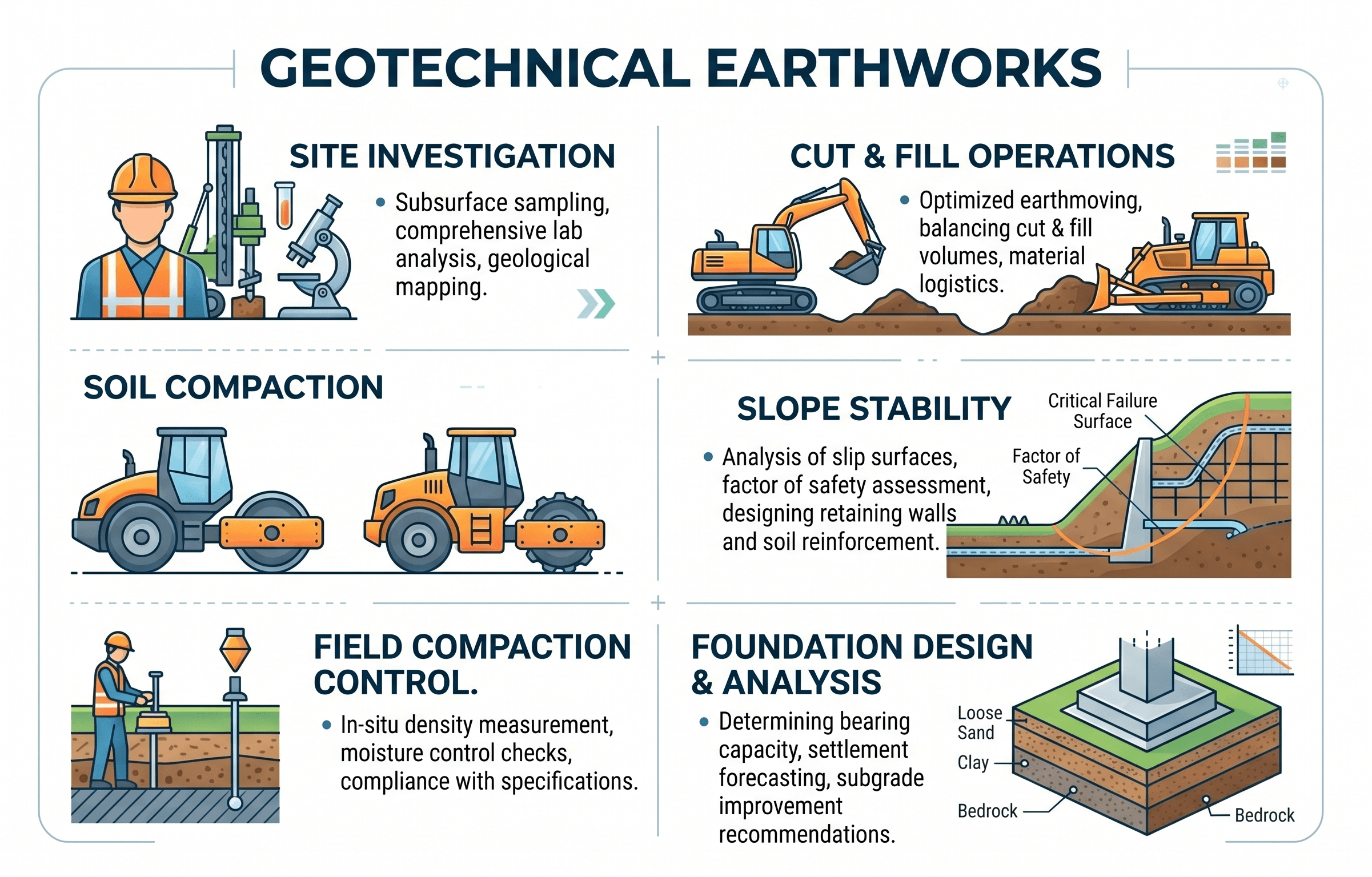
Notice that the diagram is not just about grading. It links geometry to material behavior. That is the geotechnical difference: every cut, fill, and drainage decision changes density, strength, compressibility, and long-term stability.
What is geotechnical earthworks?
Geotechnical earthworks are the planning, excavation, hauling, placement, moisture conditioning, compaction, and stabilization of soil and rock to create a finished ground surface that meets both geometric and engineering requirements. On a drawing, earthworks might look like cut and fill lines. In the field, they are about creating a foundation system, roadway platform, embankment, or backfill mass that will not settle excessively, soften under water, lose slope stability, or fail to support the intended loads.
That distinction matters. A site can be graded to the correct elevation and still perform poorly if the fill was placed too wet, compacted inconsistently, or built with unsuitable material. Geotechnical earthworks therefore combine production thinking with soil behavior. The contractor cares about moving material efficiently. The geotechnical engineer cares about whether the placed material achieves the target dry density, moisture range, shear strength, drainage behavior, and deformation response.
This is why earthwork specifications often control much more than final grade. They may define acceptable borrow sources, maximum lift thickness, scarification requirements, moisture limits relative to optimum, proof-rolling criteria, undercut triggers, and field testing frequency. For background on the broader discipline, see What is Geotechnical Engineering.
Core principles, variables, and units
The main earthwork challenge is controlling how soil structure changes during construction. Excavation disturbs the soil. Placement in lifts rearranges particles. Compaction reduces void ratio and increases dry density. Water content changes how easily particles move during compaction and how the soil behaves after construction. Drainage controls whether the material stays strong or degrades over time.
Key variables and typical ranges
Engineers usually track density, water content, lift thickness, gradation, fines content, and the presence of problematic behaviors such as expansion, collapse, organic contamination, or high compressibility. On many projects, the specification language reduces to a few simple field questions: Is the material acceptable? Is it near the right moisture? Was it placed in the right lift thickness? Did it achieve the required compaction?
- \(w\) Water content, usually reported in percent. Small deviations from optimum can strongly affect compactability and strength.
- \(\gamma_d\) Dry unit weight, often pcf or kN/m³. This is the density most earthwork specs are trying to control.
- OMC Optimum moisture content from laboratory compaction testing. Field moisture is commonly managed relative to this target.
- MDD Maximum dry density from the lab compaction curve. Field percent compaction is typically based on this value.
- Lift The thickness of loose material placed before compaction. Thick lifts often look productive but frequently produce weak lower zones.
- CBR / strength Project-specific strength or support indicators used more heavily for pavements, working platforms, and subgrades.
A compaction requirement alone is incomplete. Good earthwork control nearly always pairs density with moisture and material suitability, not density by itself.
Decision logic and earthwork workflow
Most geotechnical earthwork problems follow a repeatable workflow. First, identify what the finished ground must do: support shallow foundations, form an embankment, act as reinforced backfill, serve as pavement subgrade, or provide stable geometry around utilities or drainage features. Then work backward to determine the material properties and construction controls needed to achieve that performance.
Define performance requirement → characterize in-place and borrow materials → separate acceptable from unsuitable soils → set moisture and lift controls → compact and test each zone → verify drainage and slope stability → adjust the approach when field conditions differ from the investigation.
In real projects, this means zoning the site rather than treating all soil the same. Structural pad fill, retaining wall backfill, trench backfill, general grading fill, and topsoil are rarely interchangeable. A granular material that is excellent for drainage may be poor for erosion control on a steep slope. A clayey fill that can build a low-permeability core may be a poor choice directly beneath a slab if expansive behavior is a concern.
This decision-making also ties directly into nearby geotechnical topics such as Compaction Test, Geosynthetics, and retaining system design.
Equations and calculations
Earthworks are field-heavy, but a few equations are central to interpretation. The first is the relationship between bulk and dry unit weight:
Here, \( \gamma_d \) is dry unit weight, \( \gamma \) is moist or bulk unit weight, and \( w \) is water content expressed as a decimal. This matters because compaction targets are normally based on dry density, not total wet mass.
The second common field calculation is percent compaction:
If the project requires 95 percent compaction, the field dry unit weight must be at least 95 percent of the maximum dry unit weight from the selected laboratory compaction method. This sounds simple, but it only works when the lab test method, soil type, and field placement method are compatible.
For planning haul quantities, engineers also think in terms of cut, loose, and compacted volumes. That is where shrink and swell factors enter. Excavated material often occupies more volume after loosening, then less again after placement and compaction. The exact factors are material-dependent and should be treated as project estimates rather than universal constants.
Worked example
Example: controlled fill for a building pad
Suppose a building pad requires compacted fill beneath shallow foundations. The lab compaction test reports a maximum dry density of 118 pcf and an optimum moisture content of 12 percent. The specification requires at least 95 percent compaction, with moisture within a workable range around optimum.
A field test on one lift reports a moist unit weight of 126 pcf and a water content of 10 percent. First compute dry unit weight:
Then compute percent compaction:
On density alone, the lift passes. But that is not the end of the judgment. The engineer still asks whether the soil was compacted uniformly across the lift, whether the moisture is appropriate for the soil’s plasticity, whether the lift was too thick, and whether the pad sits over a soft pocket or poorly stripped area. A passing test point does not automatically prove the whole zone is acceptable. That is why proof-rolling, observation, and test spacing matter.
Engineering judgment and field reality
Earthwork performance is often controlled less by the written spec than by variability in the field. Borrow that looked acceptable in the pit may change within a few truckloads. A cut slope can expose wetter, softer, or more fissured material than the borings suggested. A rain event can move an otherwise workable site from efficient production to rutting, pumping, and failed compaction tests in a single day.
Experienced geotechnical engineers watch for transitions: topsoil left in place below fill, hidden wet seams, desiccated crust over soft clay, groundwater seepage at a cut face, and oversized clods that survive compaction but later break down. They also know that equipment matters. A sheepsfoot roller, smooth drum, and pneumatic roller do not produce the same response in the same soil.
Passing density numbers can hide poor support if the soil is pumping, laminated, frozen, or placed over a weak underlying layer. Earthworks succeed when the whole section behaves well, not when a spreadsheet of test points looks neat.
This is also where field classification and laboratory data must be reconciled. A soil can meet a compaction target and still be the wrong material for drainage, shrink-swell behavior, or erosion resistance. Good earthwork oversight constantly asks whether the material being built matches the function of the zone being built.
Where this method breaks down
Standard earthwork rules begin to break down when the material is highly sensitive to moisture, structure, or disturbance. Examples include soft high-plasticity clays, collapsible soils, organics, peat, frozen ground, expansive soils, and weak fills placed over very soft subgrades. In those conditions, simply specifying a percent compaction target may not capture the real performance risk.
The method also breaks down when groundwater control is treated as separate from earthworks. A fill that performs well when unsaturated may soften badly if seepage develops. Likewise, a cut slope that appears stable during dry weather can deteriorate after infiltration or excavation-induced stress relief. On difficult sites, earthworks must be integrated with drainage, staged loading, undercut and replacement, stabilization additives, or geosynthetic reinforcement rather than treated as routine grading.
Another breakdown point is assuming all “good test results” mean the same thing across all specifications. The selected laboratory compaction method, the type of field density test, and the applicable acceptance criteria should all match the actual material and project purpose.
Common pitfalls and engineering checks
- Failing to separate suitable structural fill from general excavated material.
- Placing lifts too thick, which often leaves under-compacted zones near the bottom.
- Ignoring moisture conditioning and trying to “roll in” density on soil that is too wet or too dry.
- Skipping drainage details that later cause softening, seepage erosion, or slope distress.
- Assuming a passing density number solves weak subgrade or buried topsoil problems.
One of the most expensive mistakes is building fill over a soft or contaminated foundation layer without stripping, proof-rolling, or undercutting first. The compacted fill may look good while the support beneath it is still poor.
Always ask what actually controls performance: bearing support, settlement, slope stability, erosion, drainage, or constructability. The answer should drive both the material selection and the acceptance testing.
| Parameter | Symbol | Typical units | Why it matters |
|---|---|---|---|
| Water content | \(w\) | % | Controls compactability, workability, and short-term strength. |
| Dry unit weight | \(\gamma_d\) | pcf or kN/m³ | Core acceptance metric for many engineered fill specs. |
| Lift thickness | — | in. or mm | Thicker lifts often reduce compaction uniformity. |
| Plasticity | PI | dimensionless | Helps judge moisture sensitivity and shrink-swell behavior. |
| Groundwater/seepage | — | site-specific | Can dominate stability, pumping, and long-term durability. |
Visualizing geotechnical earthworks as a system
A useful way to visualize geotechnical earthworks is as a chain of cause and effect rather than a single construction activity. Material type influences water sensitivity. Water content affects compaction response. Compaction changes density and stiffness. Drainage affects whether those gains are preserved. Geometry changes stress paths and slope behavior. When one link is ignored, the whole system becomes less reliable.
In other words, earthworks are a performance system built from soil, water, equipment, sequencing, and verification.
Relevant standards and design references
Exact requirements are project-specific, but geotechnical earthworks commonly rely on a core group of laboratory, field, and agency references.
- ASTM D698: Standard Proctor compaction. Often used for general earthwork control where a lower compactive effort is appropriate.
- ASTM D1557: Modified Proctor compaction. Common where higher compaction energy better matches project requirements, especially for structural fills and transportation-related work.
- ASTM D6938: In-place density and water content by nuclear methods. Frequently used for field acceptance testing when properly correlated and managed.
- ASTM D1556 / ASTM D2167: Sand cone and rubber balloon methods for in-place density, still useful where nuclear methods are not preferred or available.
- Agency specifications and geotechnical reports: DOT standards, municipal grading manuals, and project geotechnical recommendations usually control zoning, moisture ranges, undercut criteria, and acceptance frequency.
The key is not memorizing standard numbers in isolation. It is understanding how the selected test method connects to the material being placed and to the performance the project actually needs.
Frequently asked questions
Earthworks can simply mean reshaping the ground by cutting, filling, and grading. Geotechnical earthworks add performance requirements such as density, moisture control, settlement behavior, drainage response, and stability so the finished ground works as part of the engineered system.
The main controls are usually material suitability, moisture content, compaction target, lift thickness, groundwater, and drainage. Which one dominates depends on whether the earthwork is supporting a structure, forming an embankment, acting as backfill, or creating a pavement platform.
They stop being enough when soils are highly variable, very wet, expansive, collapsible, organic, frost-susceptible, or built over weak underlying ground. In those situations, density alone may not predict performance, so the project may need undercutting, stabilization, drainage upgrades, staged construction, or stronger material screening.
They show up in building pads, roadway embankments, retaining wall backfill, utility corridors, land development grading, dams, levees, and site stabilization work. Any project that depends on reshaped ground performing reliably depends on geotechnical earthworks.
Summary and next steps
Geotechnical earthworks are not just about moving material to a design elevation. They are about creating ground that behaves the way the project needs it to behave. That means matching material properties, moisture control, placement methods, drainage, and field verification to the actual engineering function of each earthwork zone.
In many projects, the design is only as reliable as the fill beneath it, the slope behind it, or the drainage path through it. The best earthwork decisions therefore come from combining soil mechanics with construction judgment: know the material, control the water, build in lifts, verify performance, and adjust quickly when field conditions depart from the report.
Once you understand that workflow, earthworks become much easier to analyze. You can start to see why compaction data, borrow quality, groundwater, and sequencing matter so much—and why seemingly small field shortcuts can create major performance problems later.
Where to go next
Continue your learning path with these geotechnical follow-ons.
-
Read a deeper dive on compaction testing
Helpful for understanding Proctor curves, field density testing, and what percent compaction actually means.
-
Study geosynthetics in earthwork systems
A strong next step for separation, reinforcement, filtration, drainage, and soft-ground construction.
-
Review soil consolidation
Useful when earthworks interact with soft compressible soils and long-term settlement becomes part of the design problem.