Key Takeaways
- Core idea: A circuit breaker is a resettable protective switching device that opens a circuit when current or fault conditions become unsafe.
- Engineering use: Breakers protect conductors, switchgear, transformers, motors, feeders, and branch circuits by interrupting overloads, short circuits, and selected ground or arc faults.
- What controls it: Breaker selection depends on amp rating, voltage rating, interrupting rating, trip curve, poles, equipment compatibility, and coordination with nearby protective devices.
- Practical check: The breaker handle amp rating alone is not enough; available fault current, equipment listing, and trip behavior must also be reviewed.
Table of Contents
Introduction
Circuit breakers protect electrical circuits by automatically opening the current path during unsafe conditions such as overloads, short circuits, and certain ground or arc faults. In power systems engineering, a breaker is not just an on/off switch; it is a rated interrupting device that must match the load, conductor, voltage, available fault current, equipment, and protection coordination plan.
How a Circuit Breaker Trips
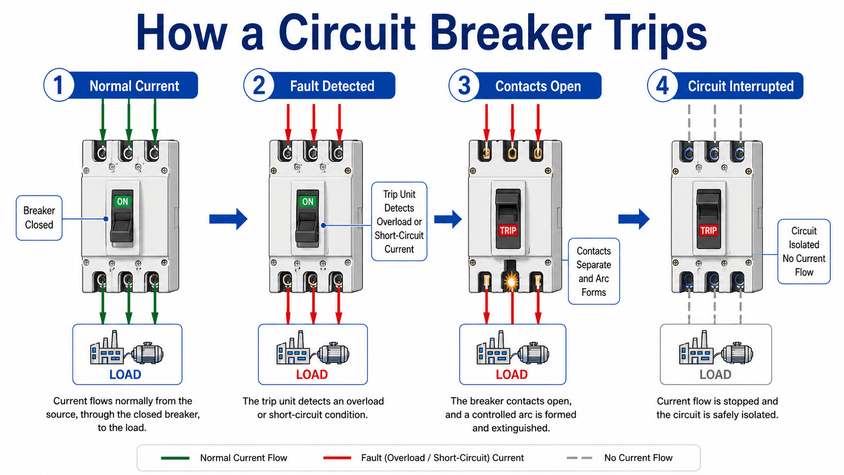
Notice that the breaker performs both a sensing function and an interruption function. A tripped breaker opens the circuit electrically, but it should not always be treated as the same thing as a visible isolation device used for switching or maintenance isolation.
What Is a Circuit Breaker?
A circuit breaker is an electrical protective device designed to carry normal load current and open automatically when current exceeds safe limits. It usually includes current-carrying contacts, an operating mechanism, a trip unit or relay input, terminals, insulation, and a method of controlling the arc created when the contacts separate.
In a residential panel, the breaker may protect a single branch circuit. In industrial and utility systems, breakers can be part of switchgear, motor control centers, feeder protection, transformer protection, generator protection, and substation protection schemes. The same core idea applies: the breaker must interrupt the right circuit fast enough to limit damage without unnecessarily shutting down healthy parts of the system.
A breaker protects the circuit it serves. That means conductor ampacity, equipment rating, available short-circuit current, enclosure listing, and upstream/downstream coordination all matter.
Main Parts of a Circuit Breaker
Circuit breaker designs vary by voltage class and application, but most breakers contain the same basic functional pieces: a current path, a trip decision element, a mechanical opening system, and an interruption chamber that handles the arc. Knowing these parts helps explain why breaker ratings are more than a handle number.
| Breaker part | What it does | Why it matters in engineering review |
|---|---|---|
| Frame or case | Provides insulation, mechanical support, and containment for the breaker assembly. | Frame size and construction influence current rating, interrupting duty, mounting, and equipment compatibility. |
| Contacts | Carry current when closed and separate when the breaker trips or is opened. | Contact condition affects heating, voltage drop, interruption performance, and maintenance reliability. |
| Operating mechanism | Stores and releases mechanical energy to open or close the breaker contacts. | The mechanism must open quickly and reliably even under fault conditions. |
| Trip unit | Detects overloads, short circuits, ground faults, or programmed trip conditions. | Trip behavior controls protection speed, nuisance tripping, and selective coordination. |
| Arc chute or arc chamber | Divides, cools, stretches, or otherwise extinguishes the arc after contacts separate. | Arc control is central to the breaker voltage rating and interrupting rating. |
| Terminals and bus connections | Connect the breaker to conductors, bus bars, panelboards, switchboards, or switchgear. | Loose or incorrect terminations can create heat, failure, and unreliable protection. |
| Handle or status indicator | Shows whether the breaker is open, closed, or tripped and allows manual operation. | Handle position helps troubleshooting, but it does not replace verification of absence of voltage where required. |
How Circuit Breakers Work
During normal operation, current flows through the breaker contacts to the load. When the current becomes abnormal, the trip unit or protective relay triggers the operating mechanism. The contacts separate, an arc forms, and the breaker must extinguish that arc while preventing restrike or damage beyond its rating.
Thermal-Magnetic Trip Units
A thermal-magnetic breaker uses thermal behavior for sustained overloads and magnetic behavior for high-current short circuits. The thermal element responds more slowly as heat builds, which allows brief temporary overloads. The magnetic element responds much faster when current rises sharply during a fault.
Electronic Trip Units
Electronic trip breakers use sensors and electronics to provide more flexible trip functions. Larger molded-case and power circuit breakers may allow long-time, short-time, instantaneous, and ground-fault settings. These settings are important for coordination because they control how the breaker behaves across different current levels.
Relay-Controlled Breakers
Medium-voltage and high-voltage breakers often rely on protective relays to detect abnormal conditions. In that arrangement, current transformers feed the relay, the relay decides whether to trip, and the breaker mechanism physically interrupts the circuit through a trip coil and control circuit.
What Circuit Breakers Protect Against
Circuit breakers are most often associated with overcurrent, but the reason for high current can vary. An overload is different from a bolted short circuit, and both are different from ground-fault or arc-fault protection. Understanding the difference helps explain why breakers have time-current curves instead of one simple trip point.
| Condition | What is happening | Typical breaker response |
|---|---|---|
| Overload | Current is above the intended load level for too long, such as an overloaded feeder or motor circuit. | Inverse-time or long-time trip behavior allows short temporary increases but opens before conductors overheat. |
| Short circuit | A low-impedance path forms between conductors or phases, causing current to rise rapidly. | Instantaneous or short-time protection trips much faster because equipment stress is severe. |
| Ground fault | Current leaves the intended circuit path and returns through ground or bonding paths. | Ground-fault protection may trip based on residual current or a relay/breaker ground-fault function. |
| Arc fault | An unintended arcing condition creates heat and ignition risk without always producing a large bolted-fault current. | Arc-fault breakers use sensing electronics to recognize arcing signatures and open the circuit. |
This is why a breaker that works well for one application may be wrong for another. Motor starting, transformer inrush, long feeders, high available fault current, and sensitive electronics can all affect the breaker type and settings.
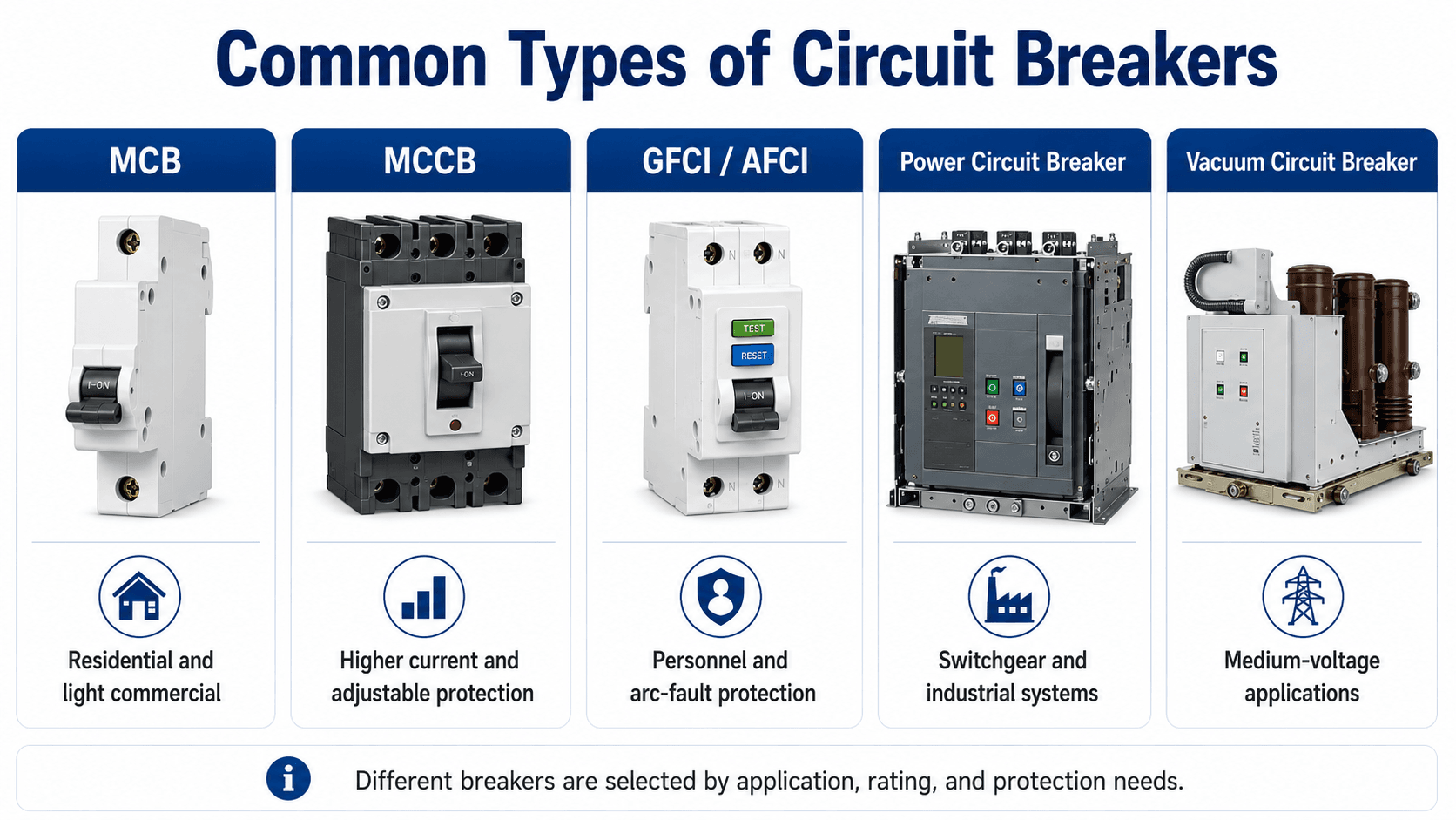
Types of Circuit Breakers
The most common circuit breaker categories include miniature circuit breakers, molded-case circuit breakers, ground-fault and arc-fault breakers, low-voltage power circuit breakers, vacuum circuit breakers, and high-voltage breakers used in utility or substation equipment.
| Breaker type | Typical use | What to watch |
|---|---|---|
| MCB | Residential, light commercial, and small branch-circuit protection. | Usually fixed trip characteristics; panel compatibility and interrupting rating still matter. |
| MCCB | Commercial and industrial feeders, panels, equipment circuits, and larger loads. | May offer adjustable trip settings, higher current ratings, and multiple interrupting ratings. |
| GFCI / RCD / RCCB | Personnel shock protection and ground-fault detection in selected circuits. | Ground-fault protection and overcurrent protection are different functions unless combined in one listed device. |
| AFCI | Arc-fault protection where arcing and fire-risk conditions are a concern. | Trips based on arcing signatures, not only current magnitude. |
| Low-voltage power circuit breaker | Switchgear, large services, main breakers, and industrial distribution. | Trip settings, short-time ratings, maintenance, and coordination become central design issues. |
| Vacuum circuit breaker | Medium-voltage switchgear and feeder protection. | Often works with protective relays, current transformers, control power, and trip circuits. |
| SF6 or high-voltage breaker | Substations and transmission-level switching and protection. | Application is driven by insulation, interrupting medium, maintenance practices, and utility standards. |
Circuit Breaker Ratings Explained
The most common mistake is treating a breaker as if the amp number on the handle tells the whole story. In engineering review, the amp rating is only one part of the device application. Voltage, available fault current, trip behavior, and equipment compatibility can be just as important.
| Rating or characteristic | Why it matters | Engineering implication |
|---|---|---|
| Ampere rating | Defines the current the breaker is intended to carry under specified conditions. | Must be coordinated with load current, continuous load rules, conductor ampacity, and equipment limits. |
| Voltage rating | Controls whether the breaker insulation and interrupting design are suitable for the system voltage. | A breaker rated for the wrong voltage may not safely interrupt a fault. |
| Interrupting rating | Defines the maximum fault current the breaker can safely interrupt at a stated voltage. | Must exceed the available short-circuit current at the breaker location. |
| Trip curve or trip settings | Controls how fast the breaker opens at different current levels. | Affects nuisance tripping, motor starting, equipment protection, and selective coordination. |
| Number of poles | Determines how many conductors are opened together. | Must match the circuit type, voltage arrangement, and system grounding requirements. |
| AC or DC rating | DC arcs do not naturally pass through zero like AC current. | DC applications require breakers specifically rated and applied for DC interruption. |
| Enclosure or panel compatibility | Breakers are listed and tested with specific equipment configurations. | A breaker that physically fits is not automatically acceptable for that panel or switchgear. |
Interrupting Rating vs Amp Rating
Amp rating describes normal current-carrying application. Interrupting rating describes the maximum fault current the breaker can safely interrupt at a specified voltage. A 100 amp breaker may be acceptable for load current but still unacceptable if it is installed where available short-circuit current exceeds the breaker interrupting rating.
Available fault current depends on source strength, transformer size and impedance, conductor length, conductor impedance, upstream equipment, and system configuration. For more background on fault current and equipment duty, see short circuit analysis.
A breaker can have the correct amp rating and still be the wrong breaker if the available fault current exceeds the interrupting rating or if the breaker is not compatible with the equipment it is installed in.
Where Circuit Breakers Are Used in Power Systems
Circuit breakers appear at many levels of an electrical system, from small branch circuits to medium-voltage feeders and utility substations. The breaker’s role changes with the system level, but the review questions stay similar: what is being protected, what fault current can occur, how quickly should the breaker open, and what must remain energized?
| System location | Breaker role | Engineering focus |
|---|---|---|
| Panelboards | Branch-circuit and small feeder protection for lighting, receptacles, and equipment circuits. | Conductor protection, panel compatibility, nuisance tripping, and proper circuit identification. |
| Switchboards | Service and feeder protection in commercial and industrial facilities. | Interrupting rating, service equipment requirements, feeder loading, and downstream coordination. |
| Switchgear | Main, tie, feeder, and industrial distribution protection. | Protective settings, maintenance access, arc energy, short-time ratings, and selective coordination. |
| Motor control centers | Motor feeder or branch-circuit protection near starters and drives. | Motor starting current, overload coordination, short-circuit protection, and equipment fault duty. |
| Medium-voltage substations | Relay-controlled feeder, transformer, bus, and equipment protection. | Protective relays, current transformers, trip circuits, vacuum breakers, and coordination studies. |
| Utility distribution and transmission | Fault interruption for feeders, substations, transformers, and high-voltage lines. | System stability, reclosing philosophy, protection zones, insulation level, and utility standards. |
For more context on breaker assemblies, see switchgear. For relay-controlled breaker applications, see protective relays.
Circuit Breaker Coordination
In a coordinated power system, the breaker closest to the fault should normally trip first while upstream breakers remain closed. This limits the outage area and keeps unaffected loads energized. Coordination is especially important in switchgear lineups, feeders, critical facilities, industrial plants, and systems with multiple protective devices in series.

Trip Curves and Time-Current Behavior
A breaker does not trip at one exact current for every situation. Time-current behavior defines how long the device waits at different current levels. Lower overcurrents may require a time delay so motors can start or temporary inrush can pass. High short-circuit currents usually require much faster operation.
Coordination is commonly evaluated using time-current curves, not only one-line diagrams. Engineers compare downstream and upstream curves to see whether the closest device clears the fault first across the expected range of fault currents.
Where Coordination Gets Difficult
Coordination becomes harder when downstream and upstream trip curves overlap, when instantaneous trips operate at similar current levels, when available fault current is high, or when the system uses a mixture of fuses, molded-case breakers, power breakers, and relay-controlled breakers.
Circuit Breaker vs Fuse vs Disconnector
Circuit breakers, fuses, and disconnectors are often located near each other in power systems, but they do different jobs. Confusing them can lead to poor protection decisions or unsafe isolation assumptions.
| Device | Main function | Practical distinction |
|---|---|---|
| Circuit breaker | Interrupts current automatically during selected abnormal conditions and can usually be reset. | Must be rated for load current, voltage, interrupting duty, and coordination requirements. |
| Fuse | Melts under overcurrent and opens the circuit once. | Can provide fast current-limiting protection, but must be replaced after operation. |
| Disconnector | Provides isolation, often with a visible open point in higher-voltage systems. | Not the same as a fault-interrupting breaker; use and operating sequence depend on equipment design. |
For a deeper comparison of isolation devices, see the Turn2Engineering guide to disconnectors. For broader protection context, start with overcurrent protection.
Circuit Breaker Selection Sanity Check
A breaker review should start with the circuit it protects, not with a catalog number. The goal is to confirm that the breaker can carry normal load, interrupt credible faults, coordinate with the system, and remain compatible with the installed equipment.
Start with the load and conductor, verify the system voltage, check available fault current, confirm the interrupting rating, review trip behavior, confirm equipment compatibility, and then evaluate coordination with upstream and downstream devices.
| Breaker review check | What to look for | Why it matters |
|---|---|---|
| Load current | Normal amps, continuous load behavior, motor starting, transformer inrush, or cyclic duty. | The breaker should carry expected load without nuisance tripping while still protecting the circuit. |
| Conductor ampacity | Wire or cable size, insulation temperature, installation method, and derating conditions. | The breaker must protect the conductor from overheating under overload conditions. |
| Available fault current | Short-circuit current at the actual breaker location, not just at the service entrance. | The interrupting rating must be high enough for the fault duty at that point in the system. |
| Trip curve or settings | Long-time, short-time, instantaneous, and ground-fault behavior where adjustable settings exist. | Trip behavior affects equipment protection, uptime, and coordination with other protective devices. |
| Equipment compatibility | Panelboard, switchboard, switchgear, enclosure, bus rating, terminals, and manufacturer/listing requirements. | Physical fit does not prove electrical or listing compatibility. |
| Environment and condition | Heat, dust, corrosion, moisture, vibration, previous trip history, and visible thermal damage. | Field conditions can change how reliably the breaker operates over time. |
Example: Why Amp Rating Is Not Enough
Consider a 480 V feeder where the load calculation suggests a 100 A breaker. If a short-circuit study shows 22 kA of available fault current at the panel, a 100 A breaker with a 10 kA interrupting rating would not be acceptable for that location even though the amp rating may look correct for the load.
What the Review Should Catch
The breaker must be rated for the system voltage, have an interrupting rating suitable for the available fault current, be compatible with the panel or switchgear, and have trip behavior that coordinates with the rest of the system. A better solution may require a different breaker series, different interrupting rating, current-limiting protection, an engineered series rating, or changes to the distribution design.
Engineering Meaning
This example is why breaker sizing and breaker application are related but not identical. A sizing calculation can estimate the amp rating, but engineering review must also verify short-circuit duty, installation compatibility, and coordination. For load-based sizing context, use the breaker size calculator as a starting point, not as the final equipment application decision.
Engineering Judgment and Field Reality
Real breaker applications are affected by more than a clean one-line diagram. Loose terminations create heat. Old equipment may have limited replacement options. Adjustable trip settings may be changed without a full coordination review. A breaker may trip because it is doing its job, because a load has changed, or because the breaker or connection has deteriorated.
Repeatedly resetting a breaker without understanding the cause can hide a serious fault, overloaded circuit, loose connection, failing motor, insulation problem, or incorrect protective device application.
In larger systems, protective relays may make the trip decision while the breaker performs the interruption. That distinction matters: the relay settings, current transformers, trip coil, DC control power, breaker mechanism, and maintenance condition all affect whether the fault is cleared correctly.
When This Breaks Down
The simplified idea that “high current trips the breaker” is useful for beginners, but it breaks down when the application involves inrush current, high fault duty, adjustable trip units, series ratings, selective coordination, DC circuits, or medium-voltage relay-controlled breakers.
- High inrush current: Motors, transformers, and capacitors can draw short-duration current that should not always trip the breaker.
- High available fault current: A breaker with the right amp rating can still be unsafe if its interrupting rating is too low.
- Trip curve overlap: Upstream and downstream breakers may trip together if coordination is not checked.
- DC applications: DC fault interruption is different because the current does not naturally cross zero each cycle.
- Equipment aging: Heat, corrosion, contamination, and mechanical wear can reduce reliability even if the nameplate rating looks acceptable.
Common Mistakes and Practical Checks
Most breaker mistakes come from treating the device as a simple switch or assuming one rating answers every question. Engineers and technicians should look at the breaker as part of a complete protection system.
- Upsizing to stop nuisance trips: A larger breaker may allow conductors or equipment to overheat before protection operates.
- Ignoring interrupting rating: The breaker must be able to safely interrupt the available short-circuit current.
- Mixing incompatible breakers and panels: Similar shape does not mean the breaker is listed or suitable for the equipment.
- Using AC breakers on DC circuits without verification: DC interruption requires appropriate ratings and application rules.
- Forgetting coordination: The main breaker should not trip for every downstream branch fault if selective coordination is required.
- Treating GFCI and AFCI as the same protection: GFCI protection is primarily related to ground-fault shock risk, while AFCI protection is focused on arcing conditions and fire-risk reduction.
Do not assume the breaker handle rating is the full design answer. Always review conductor protection, voltage, interrupting rating, device compatibility, and the reason the breaker is tripping.
Standards, Markings, and Design References
Breaker markings and ratings are part of how engineers, inspectors, and installers confirm whether a device is suitable for a specific circuit. The article can explain the concepts, but final application depends on the installed equipment, applicable codes, manufacturer instructions, and project criteria.
- UL Solutions marking guidance: UL Solutions molded case circuit breaker marking guide explains breaker certification, listing context, markings, ratings, and special-use markings that help readers interpret molded-case breaker labels.
- Breaker markings engineers commonly check: Ampere rating, voltage rating, interrupting rating, number of poles, AC/DC suitability, catalog identification, terminal markings, current-limiting markings, and special markings such as ground-fault, arc-fault, switching-duty, or high-intensity-discharge use where applicable.
- Code and standard families: NEC overcurrent protection requirements, UL 489, UL 1077, IEC 60947-2, IEC 60898-1, and manufacturer data may all be relevant depending on the breaker type and project location.
- Engineering use: Engineers use markings, short-circuit studies, coordination studies, equipment data, and field conditions together when reviewing breaker selection and settings.
Frequently Asked Questions
A circuit breaker protects a circuit by opening the current path when it detects an unsafe condition such as overload, short circuit, or some ground-fault and arc-fault conditions. In power systems, the breaker must interrupt current safely and coordinate with nearby protective devices.
A circuit breaker trips when the current or fault condition exceeds the breaker trip unit setting or characteristic. Common causes include sustained overloads, short circuits, ground faults, motor starting problems, damaged equipment, loose connections, heat, or a breaker that is not matched to the application.
Interrupting rating is the maximum fault current a breaker is designed to safely interrupt at a specified voltage. It must be compared with the available short-circuit current at the installation point, because a breaker can have the correct amp rating and still be unsafe if its interrupting rating is too low.
A circuit breaker is normally resettable after it opens, while a fuse melts and must be replaced. Both can protect against overcurrent, but they differ in interrupting behavior, maintenance, coordination, cost, speed, and how easily the protective device can be restored after a fault.
Summary and Next Steps
Circuit breakers are protective switching devices that carry normal current and open the circuit when unsafe current or fault conditions occur. In power systems, their value depends on more than tripping; they must interrupt current safely, protect the correct conductors and equipment, and coordinate with the rest of the protection system.
The most important review points are amp rating, voltage rating, interrupting rating, trip curve, equipment compatibility, and selective coordination. A breaker that is correct for one circuit may be wrong for another if the available fault current, system voltage, load behavior, or field conditions change.
Where to go next
Continue your learning path with related Turn2Engineering resources.
-
Overcurrent Protection
Learn how circuit breakers, fuses, relays, and related devices protect conductors and equipment from excessive current.
-
Short Circuit Analysis
Review how available fault current is estimated for equipment ratings, breaker interrupting duty, and protection studies.
-
Breaker Size Calculator
Estimate breaker size for basic load scenarios while keeping conductor ampacity and practical limits in mind.