Key Takeaways
- Core idea: Generator protection uses relays, CTs, VTs, breakers, excitation trip circuits, and lockout logic to isolate generator faults and unsafe operating conditions.
- Engineering use: Protection engineers use generator schemes to detect stator faults, ground faults, loss of field, reverse power, unbalance, overexcitation, voltage issues, frequency excursions, and synchronizing problems.
- What controls it: The correct scheme depends on generator size, grounding method, prime mover, excitation system, CT/VT locations, transformer connection, and owner requirements.
- Practical check: A relay list is not enough; the trip matrix must show what opens, what shuts down, what locks out, and what backs up the breaker if clearing fails.
Table of Contents
Introduction
Generator protection is the coordinated use of protective relays, instrument transformers, breakers, excitation trip circuits, lockout logic, and monitoring functions to detect generator faults and abnormal operating conditions. It protects the machine from electrical damage while helping the power system remain stable when faults, control failures, or grid disturbances occur.
Generator Protection Scheme Diagram
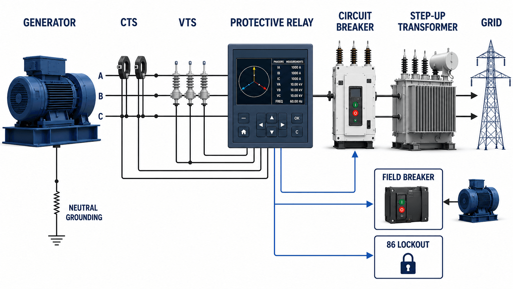
This is a simplified educational one-line diagram. Actual generator protection drawings may include additional CT circuits, VT sources, breaker failure logic, synchronizing circuits, redundant relays, event recording, alarms, and plant control interfaces.
What Is Generator Protection?
Generator protection is the protection system applied to a generator and its immediate electrical connections. It normally includes protective relays, current transformers, voltage transformers, generator breaker trips, excitation trip circuits, neutral grounding measurements, alarms, lockout logic, event records, and sometimes turbine or prime mover shutdown commands.
The key difference from ordinary feeder protection is that a generator is an active source. It has a rotating machine, a magnetic field, a prime mover, stored inertia, synchronizing requirements, and thermal limits that can be exceeded even when there is no obvious downstream short circuit.
Generator protection is not just overcurrent protection. It must detect internal winding faults, ground faults, loss of excitation, reverse power, negative sequence heating, overexcitation, frequency excursions, synchronizing problems, and abnormal system conditions that can damage the generator or destabilize the grid.
Types of Generator Protection
Generator protection is easiest to understand when the functions are grouped by what they protect. Some elements protect the stator winding, some protect the rotor or excitation system, and others supervise abnormal operating conditions or backup clearing.
| Protection category | Typical functions | What the category protects |
|---|---|---|
| Stator winding protection | 87G differential, stator ground protection, backup phase fault protection | Protects generator stator windings from internal phase faults, ground faults, and severe short-circuit conditions. |
| Rotor and field protection | 64F field ground, 40 loss of field, excitation trip circuits | Protects the rotor field system and generator excitation from ground faults, excitation loss, and unsafe field conditions. |
| Abnormal operating condition protection | 32 reverse power, 46 negative sequence, 24 V/Hz, 27/59 voltage, 81 frequency | Protects the generator from operating states that may not be direct internal faults but can cause heating, instability, or mechanical risk. |
| Synchronizing and stability protection | 25 sync-check, 78 out-of-step or pole slip protection where applied | Helps prevent unsafe breaker closing and detects loss of synchronism on larger or more critical generator installations. |
| Backup and trip logic | 51V, 21, 50BF, 86 lockout, breaker failure outputs | Provides backup fault clearing and ensures serious trips isolate the correct electrical and mechanical energy sources. |
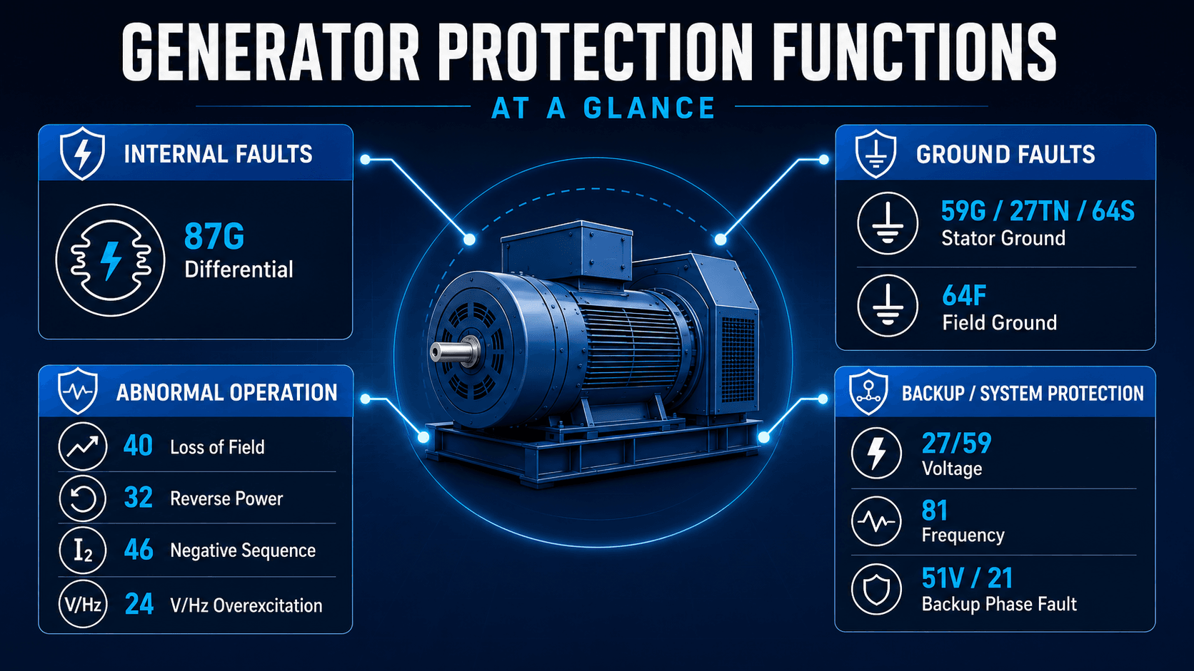
Generator Protection Relay Functions at a Glance
A generator protection relay package is usually described by ANSI device numbers. The numbers are useful because they let engineers read one-line diagrams, relay settings, trip matrices, and commissioning test sheets without relying on a specific relay manufacturer.
| Function | What it detects | Why it matters for generator protection |
|---|---|---|
| 87G Generator Differential | Internal phase faults inside the generator stator protection zone. | Trips quickly for high-risk internal faults where fast isolation helps limit winding and core damage. |
| 59G / 27TN / 64S Stator Ground | Ground faults in the stator winding or generator neutral circuit. | Ground fault sensitivity depends heavily on the generator grounding method and the portion of winding being protected. |
| 64F Field Ground | Ground faults in the rotor field circuit or excitation circuit. | A first field ground may alarm, but a second ground can create damaging rotor current paths and vibration risk. |
| 40 Loss of Field | Loss of excitation or operation outside the intended excitation capability area. | Loss of field can cause high reactive power absorption, heating, and system stability concerns. |
| 32 Reverse Power | Real power flowing into the generator instead of out of it. | Protects the prime mover from motoring conditions when the generator remains connected but mechanical input is lost. |
| 46 Negative Sequence | Unbalanced current that produces negative sequence heating in the rotor. | Protects the rotor from heating caused by phase unbalance, open conductors, or asymmetrical system faults. |
| 24 Volts per Hertz | Overexcitation caused by excessive voltage relative to frequency. | Protects the generator and connected transformer from magnetic overfluxing and heating. |
| 27 / 59 Voltage | Undervoltage or overvoltage conditions at generator terminals or related VTs. | Supports abnormal condition detection, backup protection, and control supervision. |
| 81 Frequency | Underfrequency or overfrequency operation. | Protects the generator and turbine-generator system from operation outside acceptable speed and frequency limits. |
| 78 Out-of-Step / Pole Slip | Loss of synchronism or unstable power swings where applied. | Helps large generators separate from the system in a controlled way when synchronism is lost. |
| 25 Sync-Check | Unsafe breaker closing conditions based on voltage, phase angle, and frequency difference. | Prevents closing the generator breaker when the generator and system are not properly synchronized. |
| 51V / 21 Backup Phase Fault | Voltage-restrained or voltage-controlled overcurrent, or distance backup protection where applied. | Provides backup protection, often coordinated with transformer, bus, and transmission line protection. |
| 50BF Breaker Failure | Failure of the generator breaker to clear after a trip command. | Initiates backup clearing when the local breaker does not interrupt the fault or abnormal condition as expected. |
| 86 Lockout | A serious trip condition requiring manual review before re-energization. | Prevents automatic reclose or restart after major generator protection operations. |
The exact relay package changes with machine rating, voltage class, grounding method, unit transformer arrangement, and owner philosophy. A large utility generator may have multiple specialized protection elements that are not used on a small standby generator.
Faults and Abnormal Conditions Generator Protection Must Detect
Generator protection works best when faults and abnormal operating conditions are separated clearly. A stator phase fault is a physical fault inside the machine, while reverse power or loss of excitation may be an operating condition caused by prime mover, excitation, synchronization, or system problems.
| Condition | Typical protection response | Practical engineering concern |
|---|---|---|
| Stator phase fault | 87G differential trip and lockout. | Fast clearing is important because internal generator faults can cause severe winding and core damage. |
| Stator ground fault | Neutral voltage, third harmonic, or ground fault protection depending on the grounding design. | Sensitivity and coverage depend on how the generator neutral is grounded. |
| Rotor field ground | 64F alarm or trip depending on scheme philosophy and machine criticality. | A single ground may not immediately damage the machine, but it reduces insulation margin and can become dangerous if a second ground develops. |
| Loss of field | 40 loss-of-excitation element, often with time delay or impedance-based logic. | The relay must distinguish true excitation loss from stable power swings, external faults, and limiter action. |
| Reverse power | 32 reverse power trip after a time delay. | The correct sensitivity and delay depend on prime mover type and normal shutdown behavior. |
| Negative sequence current | 46 negative sequence alarm or trip based on current magnitude and time. | Unbalanced current can heat the rotor even when phase currents do not appear extreme individually. |
| Overexcitation | 24 V/Hz protection and coordination with excitation controls. | High volts per hertz can overflux the generator and transformer magnetic cores. |
| Out-of-step operation | 78 out-of-step protection or system stability protection where applied. | Loss of synchronism can create severe torque, current, and voltage swings that require controlled separation. |
| Unsafe synchronizing | 25 sync-check supervision before generator breaker closing. | Closing out of phase can create damaging electrical and mechanical stress on the generator shaft and windings. |
| Breaker failure | Breaker failure logic starts backup tripping if the generator breaker does not clear. | The scheme must not assume the first breaker trip command will always interrupt the fault. |
Many generator trips are not caused by a visible winding failure. VT fuse issues, CT polarity errors, synchronization problems, excitation control problems, breaker failures, and incorrect trip matrix logic can all create protection events that look confusing without relay records and commissioning documentation.
Small vs Large Generator Protection Schemes
Not every generator needs the same protection scheme. A small standby generator controller may integrate basic protection functions, while a large utility generator normally requires a more complete relay package, detailed studies, redundant signals, event analysis, and a documented trip matrix.
| Generator application | Typical protection level | Design implication |
|---|---|---|
| Small standby generator | Basic overload, voltage, frequency, ground fault, engine controls, and reverse power if paralleled. | Protection may be controller-based, but paralleling and grounding still need careful review. |
| Commercial or industrial generator | Differential protection where justified, ground fault, reverse power, loss of field, negative sequence, V/Hz, voltage, frequency, and breaker control. | Protection must coordinate with facility distribution, transfer schemes, and utility interconnection requirements. |
| Plant or cogeneration unit | Expanded relay package with trip matrix, sync-check, breaker failure, excitation trips, and plant control interface. | Prime mover, process requirements, and grid export conditions strongly affect the protection philosophy. |
| Large utility generator | Comprehensive generator, transformer, excitation, synchronizing, backup, breaker failure, out-of-step, and event recording functions. | Settings normally require detailed short-circuit, stability, coordination, grounding, and equipment capability review. |
The main point is not that one scheme is always better. The protection package should match the generator’s role, available fault energy, grounding, importance to the system, and consequences of both failure to trip and false tripping.
Generator Differential and Ground Fault Protection
Differential protection is the primary high-speed protection for many serious generator stator phase faults. It compares current entering and leaving the protected zone. If the current balance does not make sense for an external load or through fault, the relay interprets the difference as an internal fault.
How 87G Defines the Protected Zone
The protected zone is created by CT locations. A fault between the CTs is internal to the zone; a fault outside the CTs should normally be seen as through current and restrained. This is why CT placement, polarity, ratio selection, and wiring are not minor details in a generator protection design.
Why Ground Fault Protection Depends on Generator Grounding
Stator ground fault protection cannot be selected correctly without knowing the grounding method. A high-resistance grounded generator behaves differently than a solidly grounded or low-resistance grounded source. Neutral voltage, residual voltage, third harmonic voltage, and differential ground methods may all be considered depending on the machine and system arrangement.
For a deeper look at the current-comparison concept behind 87G, see the Turn2Engineering guide to differential protection.
Loss of Field, Reverse Power, Negative Sequence, and V/Hz Protection
Some of the most important generator protection functions are not simple short-circuit functions. They protect the generator from operating in a condition that may look electrically possible for a short time but is damaging or unstable if allowed to continue.
Loss of Field Protection
Loss of field protection detects loss of excitation or operation outside the intended excitation capability region. When excitation is lost, a synchronous generator can begin absorbing reactive power from the system and may fall out of synchronism. The relay must be secure enough to avoid tripping for stable swings, external faults, or normal limiter action.
Reverse Power Protection
Reverse power protection detects when real power flows into the generator. This usually means the generator is motoring and driving the prime mover instead of being driven by it. The practical trip delay and pickup are tied to the prime mover, because steam turbines, gas turbines, hydro turbines, and diesel engines tolerate motoring differently.
Negative Sequence Protection
Negative sequence current comes from unbalanced phase currents. The heating effect is especially important in generator rotors because negative sequence current produces a rotating magnetic field relative to the rotor. A generator can therefore be at risk even when the issue looks like a system-side unbalance rather than an internal machine fault.
Volts-per-Hertz Protection
V/Hz protection detects overexcitation when voltage is too high for the operating frequency. This matters during startup, shutdown, frequency excursions, and excitation control problems because magnetic flux in the generator and transformer core is tied to the voltage-to-frequency ratio.
Out-of-Step and Sync-Check Context
Larger generator installations may also include 78 out-of-step protection and 25 sync-check supervision. Out-of-step protection addresses loss of synchronism after major disturbances, while sync-check helps prevent the generator breaker from closing when voltage magnitude, phase angle, or frequency difference is outside the intended synchronizing window.
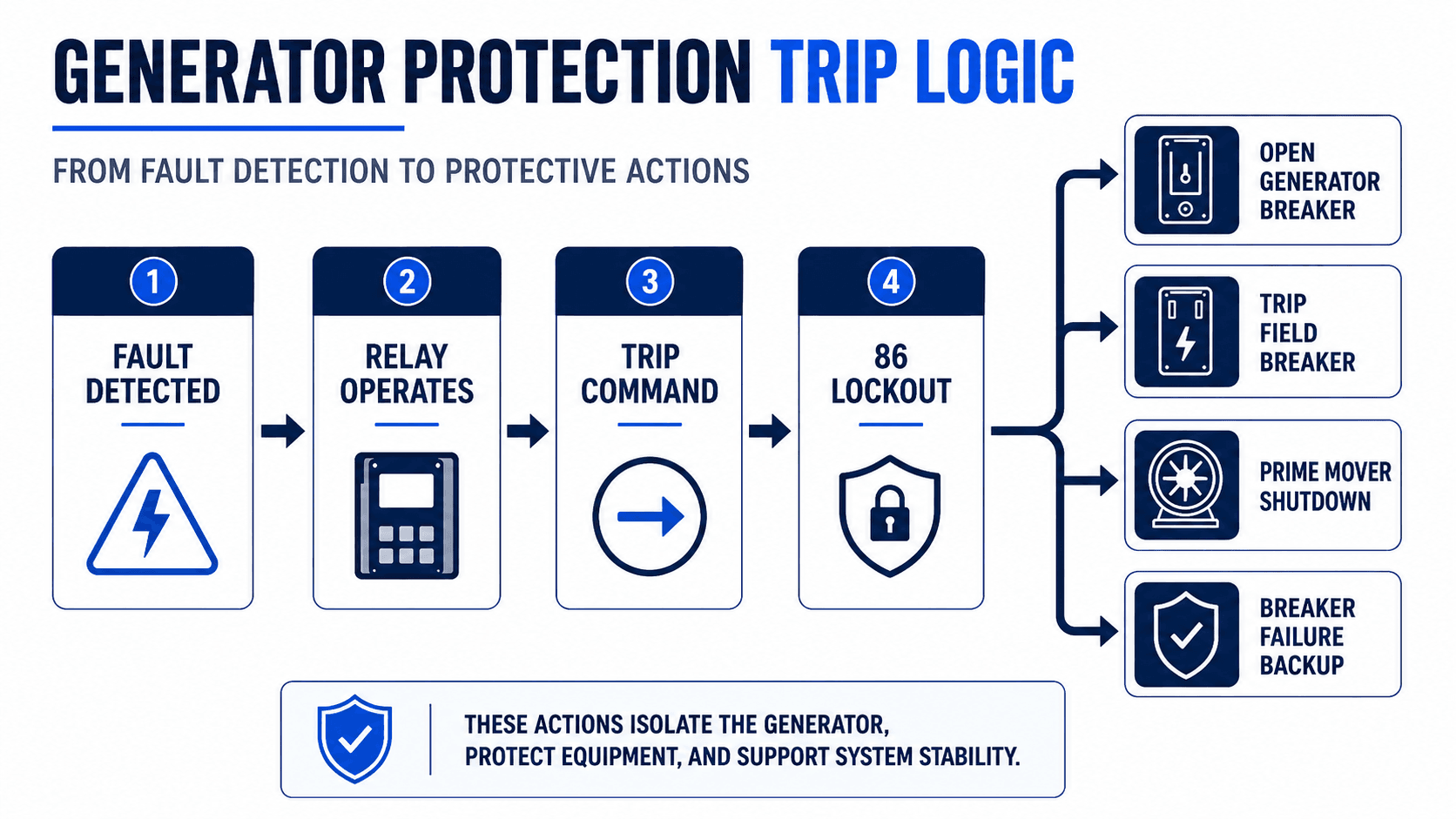
Generator Protection Trip Logic
A generator relay operation is only part of the protection system. The trip logic determines what equipment is opened, what energy sources are removed, whether the unit is locked out, and what backup action occurs if a breaker fails to clear.
Why the Trip Matrix Matters
A generator protection design should show which functions alarm, which functions trip the generator breaker, which functions trip the field breaker or excitation circuit, which functions shut down the prime mover, and which functions initiate the 86 lockout. Without that trip matrix, the relay settings may look complete while the actual shutdown behavior remains unclear.
Breaker Failure and Backup Clearing
If the generator breaker receives a trip command but current continues to flow, breaker failure logic may trip upstream or adjacent breakers. This protects the generator and surrounding system when the local interrupting device does not clear the fault as expected.
The relay decision process connects directly to the broader topic of protective relays, where the relay is the measuring and decision device while the breaker is the interrupting device.
Generator Protection Trip Matrix Example
A trip matrix helps the design team, operations team, and commissioning team understand what each protection function actually does. The example below is a practical teaching format; the final trip logic for a real project must match the equipment, owner philosophy, relay design, and plant control sequence.
| Protection function | Alarm | Trip generator breaker | Trip field or excitation | Prime mover shutdown | 86 lockout |
|---|---|---|---|---|---|
| 87G Generator Differential | No | Yes | Yes | Usually yes | Yes |
| Stator ground fault | Sometimes | Usually yes | Usually yes | Depends on scheme | Often yes |
| Loss of field | Often first stage | Yes for trip stage | Depends on excitation design | Depends on unit controls | Often yes |
| Reverse power | Sometimes | Yes after delay | Usually not primary action | Part of shutdown sequence | Depends on owner philosophy |
| Negative sequence | Alarm or trip stage | Yes for trip stage | Depends on scheme | Depends on unit controls | Depends on severity |
| V/Hz overexcitation | Often staged | Yes for severe condition | May reduce or trip excitation | Depends on plant design | Often yes for severe trip |
| VT fuse failure | Yes | Usually no | No | No | No |
| Breaker failure | Yes | Already commanded | May be commanded | May be commanded | Yes, with backup tripping |
The most useful trip matrix includes not only relay functions, but also output contacts, breaker trip coils, lockout inputs, field or excitation trip paths, turbine or engine shutdown commands, alarms, event recording, and reset requirements.
Senior Engineer Generator Protection Review Checklist
A practical generator protection review should confirm more than the presence of relay functions. It should verify the measurement sources, protection zones, trip outputs, operating limits, event records, and commissioning checks that make the scheme dependable and secure.
Start with the machine data and one-line diagram, confirm CT and VT locations, identify the protection zones, map each relay function to a protected condition, review the trip matrix, then verify the scheme through setting review, event record review, and commissioning tests.
| Review check | What to look for | Why it matters |
|---|---|---|
| Generator data | Nameplate MVA, voltage, grounding method, reactance data, excitation system, prime mover, and manufacturer protection limits. | Relay settings and element selection depend on the actual machine, not just the generic term “generator.” |
| CT and VT locations | CT polarity, ratio, wiring, saturation performance, VT source, VT fuse supervision, and protection zone boundaries. | Wrong instrument transformer assumptions can cause missed trips or false differential operation. |
| Grounding method | Neutral grounding resistor, transformer grounding arrangement, ground fault current level, and neutral measurement location. | Stator ground protection sensitivity and method depend on how the generator neutral is grounded. |
| Synchronizing controls | Sync-check supervision, breaker close permissives, voltage matching, phase angle difference, and frequency difference. | Unsafe closing can produce damaging torque and current transients even if the relay trip settings are correct. |
| Trip matrix | Which elements alarm, trip the generator breaker, trip the field or excitation circuit, shut down the prime mover, start breaker failure, and operate 86 lockout. | The protection scheme must remove the right sources of energy, not just show that a relay element exists. |
| Excitation and limiter coordination | Loss-of-field element, minimum excitation limiter, overexcitation limiter, V/Hz settings, and AVR behavior. | Generator protection should trip for unsafe operation without fighting normal excitation control action. |
| Backup coordination | Coordination with transformer protection, bus protection, line protection, overcurrent elements, and breaker failure schemes. | Generator backup protection should not trip before more selective downstream or adjacent protection unless intended. |
| Commissioning evidence | Secondary injection tests, trip output tests, lockout reset checks, breaker failure timing, relay event records, and disturbance reports. | The design is not proven until measurements, logic, outputs, event capture, and physical trips are verified together. |
Engineering Judgment and Field Reality
Generator protection design is a balance between dependability and security. Dependability means the relay trips when a real damaging condition occurs. Security means the relay does not trip for conditions it should ride through, such as stable load changes, external faults cleared by other protection, CT transients, limiter action, or expected startup and shutdown behavior.
This balance is especially important for loss-of-field, reverse power, V/Hz, out-of-step, and negative sequence functions. These elements often involve time delays, characteristic curves, directional logic, blocking logic, or supervisory conditions because the relay must distinguish harmful operation from temporary system behavior.
Event records are a major part of field reality. After a generator trip, engineers often review oscillography, sequence of events, breaker status, voltage inputs, current inputs, field conditions, and alarm history to determine whether the protection operated correctly or whether an instrumentation, control, or wiring issue created a false event.
The most expensive generator protection problems are not always missed faults. A false trip on a critical generator can remove major capacity from a plant or grid, while an insecure trip matrix can leave excitation, prime mover energy, or fault current connected longer than intended.
When This Breaks Down
A simplified generator protection diagram is useful for learning, but it breaks down when it is treated as a universal design. Real schemes depend on generator construction, grounding, transformer arrangement, owner standards, system studies, relay vendor capabilities, and the shutdown philosophy for the specific plant.
- Grounding assumptions change the scheme: A stator ground fault element selected for one neutral grounding method may not provide the same coverage on another generator.
- 87G only protects its CT-defined zone: Differential protection does not automatically protect every piece of equipment near the generator.
- Loss-of-field settings can overlap with limiter behavior: Poor coordination with the minimum excitation limiter can create false trips or delayed tripping for real excitation problems.
- Reverse power may appear during shutdown: If the pickup or delay is not coordinated with the normal shutdown sequence, the relay may trip in a way operators do not expect.
- V/Hz can be sensitive during startup and frequency excursions: Voltage and frequency must be evaluated together, not as isolated quantities.
- Negative sequence protection depends on thermal capability: Unbalance protection should reflect generator capability and expected system disturbances.
- CT and VT errors can dominate the protection result: Incorrect polarity, ratio mismatch, saturation, failed VT fuses, or poor wiring can make a correct relay setting behave incorrectly.
- Trip outputs may not match the written intent: A setting file can look complete while field wiring, lockout logic, or breaker failure initiation is still wrong.
Common Generator Protection Mistakes and Practical Checks
Generator protection mistakes often come from treating the machine like a feeder, copying a relay template without checking the one-line diagram, or focusing only on pickup values instead of the full protection system.
| Common mistake | Why it causes problems | Practical check |
|---|---|---|
| Using a generic relay template without machine data | The generator rating, grounding, excitation system, and prime mover may not match the template assumptions. | Start every review with the generator data sheet, grounding diagram, excitation data, and one-line diagram. |
| Assuming 87G protects everything near the generator | Differential protection only protects the zone defined by the CTs. | Mark the CT locations and draw the actual 87G zone on the one-line diagram. |
| Ignoring VT supervision | Voltage-dependent functions can misoperate or become blind when VT signals are lost or fused incorrectly. | Confirm VT fuse failure logic, voltage source selection, relay blocking behavior, and alarm outputs. |
| Setting reverse power without prime mover context | Motoring risk and acceptable delay vary by turbine or engine type. | Coordinate reverse power settings with prime mover guidance and shutdown sequence. |
| Treating sync-check as optional control detail | Improper generator breaker closing can create severe mechanical and electrical stress. | Review 25 sync-check permissives, close supervision, and synchronizing procedure. |
| Leaving trip logic undocumented | Operators and commissioning teams may not know which protection functions trip which devices. | Create a trip matrix that lists breaker trip, field or excitation trip, prime mover shutdown, 86 lockout, alarms, and breaker failure initiation. |
| Not coordinating generator backup with system protection | Backup elements can trip the generator unnecessarily for faults that should be cleared elsewhere. | Review coordination with transformer protection, bus protection, line protection, and overcurrent protection. |
Do not judge a generator protection scheme by the relay element list alone. The scheme is only complete when the measurements, settings, trip outputs, lockout logic, breaker failure response, event records, and commissioning tests are reviewed together.
Standards, Manuals, and Design References
Generator protection is normally designed using owner standards, utility interconnection requirements, relay manuals, generator manufacturer limits, system studies, and recognized protection guidance. A resource page can explain the scheme, but project-specific settings require the actual machine data and engineering review.
- IEEE C37.102: IEEE Guide for AC Generator Protection is a widely recognized reference for applying relays to protect AC generators from internal faults, system faults, and abnormal operating conditions.
- Project-specific criteria: Owner requirements, interconnection agreements, equipment limits, relay manuals, and utility standards may control the final relay package and trip philosophy.
- Engineering use: Protection engineers use these references with short-circuit studies, coordination studies, generator capability data, grounding details, stability review, and commissioning tests to verify the final scheme.
Frequently Asked Questions
Generator protection is the coordinated use of protective relays, CTs, VTs, breakers, excitation trip circuits, lockout logic, and monitoring functions to detect generator faults and abnormal operating conditions before they damage the machine or destabilize the power system.
Common generator protection functions include 87G differential protection, stator ground protection, field ground protection, 40 loss of field, 32 reverse power, 46 negative sequence, 24 volts-per-hertz overexcitation, 27/59 voltage protection, 81 frequency protection, 78 out-of-step protection, 25 sync-check, and 86 lockout logic.
Generator protection is different because a generator is an active source with mechanical input, excitation, rotor heating limits, synchronizing requirements, and system stability interactions. It must protect against internal faults, external system disturbances, and abnormal operating conditions, not just downstream short circuits.
87G is the ANSI device designation commonly used for generator differential protection. It compares current entering and leaving the generator stator protection zone and trips quickly when the measured difference indicates an internal phase fault.
No. Generator protection depends on generator size, voltage, grounding method, transformer connection, CT and VT locations, excitation system, prime mover type, owner requirements, relay capabilities, and manufacturer limits. A small standby generator and a large utility generator will not use the same complete protection package.
Summary and Next Steps
Generator protection is the relay-based protection system used to detect internal generator faults, ground faults, abnormal operating conditions, unsafe synchronizing, and backup clearing conditions. It combines measurement inputs, relay logic, breaker trips, excitation trips, prime mover shutdown logic, lockout functions, event records, and commissioning checks.
The most useful way to evaluate a generator protection scheme is to follow the chain from measurement to decision to action. Confirm the CTs and VTs, define the protection zones, map relay functions to failure modes, review the trip matrix, verify synchronizing and breaker failure logic, and confirm that the scheme is secure for normal operation but dependable for real damaging conditions.
Where to go next
Continue your learning path with related Turn2Engineering resources.
-
Protective Relays
Learn how relays measure current, voltage, frequency, impedance, and differential quantities before sending trip commands.
-
Differential Protection
Review the current-comparison principle behind generator differential protection and other 87-type schemes.
-
Grounding Techniques
Understand why generator grounding method strongly affects ground fault detection and protection sensitivity.