Key Takeaways
- Core idea: A reactor is an inductive power system device that adds reactance to control voltage, current, reactive power, or system behavior.
- Engineering use: Shunt reactors are commonly used for overvoltage control, while series reactors are commonly used for current limiting and impedance control.
- What controls it: Connection method, system voltage, frequency, reactance, Mvar rating, current rating, fault level, and switching duty all affect reactor application.
- Practical check: A reactor should never be selected from a simplified diagram alone; load flow, short-circuit, protection, switching, and insulation impacts must be reviewed.
Table of Contents
Introduction
Reactors in power systems are inductive devices used to add controlled reactance to an electrical network. Depending on where they are connected, reactors can absorb reactive power, control overvoltage, limit fault current, reduce inrush effects, support capacitor banks, or improve the way a transmission, substation, or distribution system behaves.
Shunt vs Series Reactors at a Glance
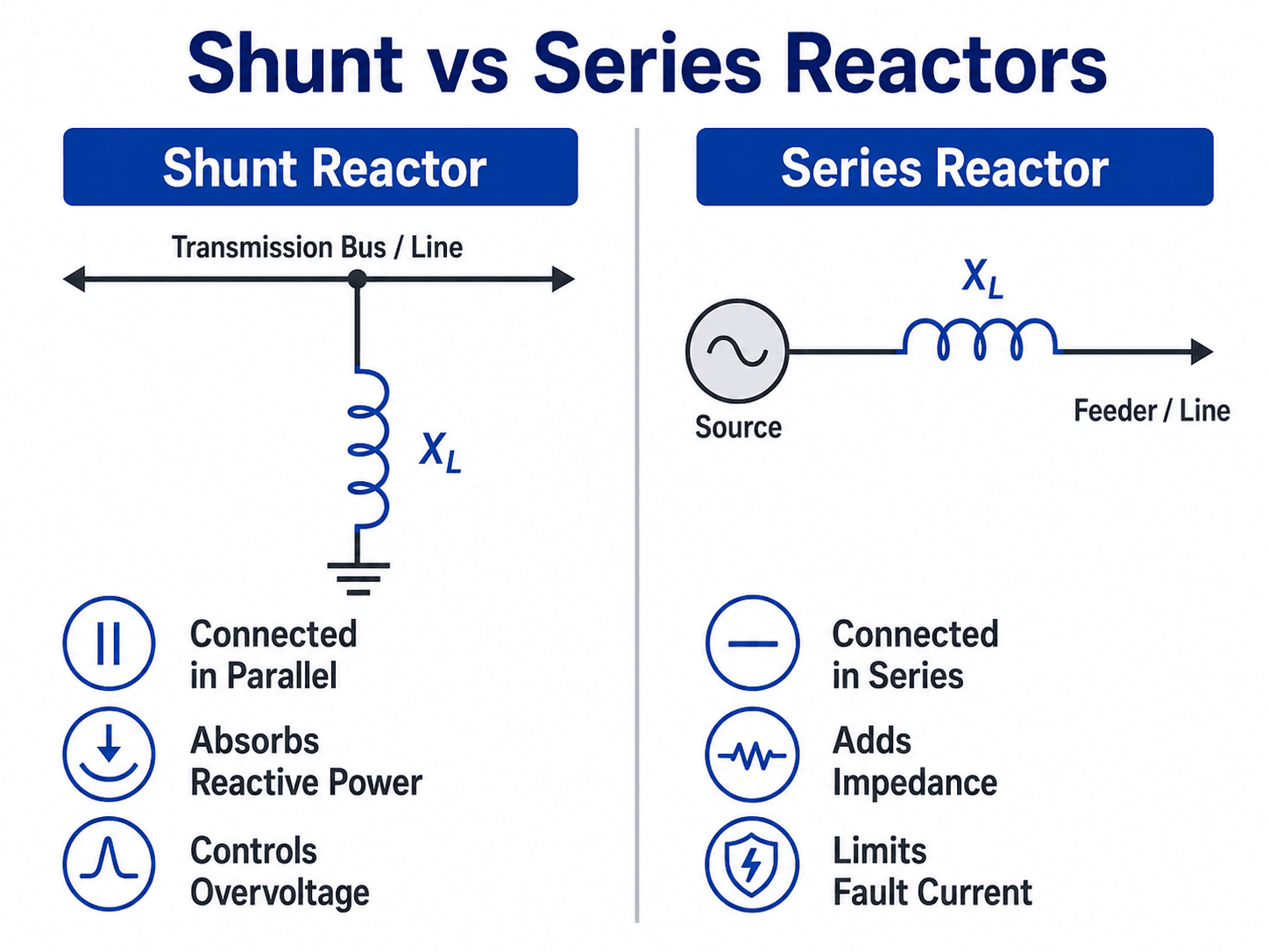
Start by looking at the connection point. If the reactor is connected in parallel with the system, think voltage and reactive power. If it is inserted in series with the circuit, think current limiting, voltage drop, and protection coordination.
What Is a Reactor in a Power System?
A power system reactor is a large-duty inductor designed for utility, industrial, transmission, substation, or distribution service. It is not a chemical or nuclear reactor. In electrical engineering, the word reactor refers to equipment that intentionally introduces inductive reactance into an AC or converter-connected power circuit.
Reactors matter because power systems are not controlled only by voltage and resistance. Alternating-current systems also depend on reactance, reactive power, system impedance, switching behavior, and short-circuit levels. A reactor gives engineers a controlled way to change those characteristics without rebuilding the entire network.
The practical insight is that a reactor does not do one single job. The same basic inductive behavior can solve different problems depending on whether the reactor is connected in shunt, installed in series, applied to a capacitor bank, connected to a neutral, or used in a filter circuit.
Why Reactors Are Used in Electrical Power Systems
Reactors are used when the system needs more reactance in a specific location. That added reactance can absorb reactive power, limit short-circuit current, reduce inrush or outrush current, change power flow between parallel paths, or help tune a filter for harmonic control.
| Power system problem | Reactor application | Engineering implication |
|---|---|---|
| High voltage at light load on long lines or cables | Shunt reactor | Absorbs capacitive reactive power so the receiving-end voltage stays closer to acceptable limits. |
| Fault current exceeds equipment interrupting or withstand rating | Series or current-limiting reactor | Adds impedance to reduce available short-circuit current, but also affects voltage drop and relay settings. |
| Capacitor bank switching creates high inrush or outrush current | Capacitor bank reactor | Limits transient current and can help reduce stress on switches, breakers, fuses, and capacitor units. |
| Ground-fault current needs to be limited | Neutral grounding reactor | Controls ground-fault magnitude while preserving enough current for reliable detection and protection operation. |
| Harmonic filtering or tuned reactive compensation is required | Filter reactor | Works with capacitors and system impedance to target selected frequency behavior. |
Before choosing a reactor, identify the actual system problem. A voltage-rise problem, a short-circuit duty problem, a capacitor switching problem, and a grounding problem may all involve reactors, but they require different connections, ratings, studies, and protection checks.
How Shunt Reactors Control Overvoltage
A shunt reactor is connected in parallel with the system, usually from a bus, line, cable, or transformer tertiary connection to ground. Its primary job is to absorb inductive reactive power so the network does not become too capacitive under light-load or no-load conditions.
Why long lines and cables create the problem
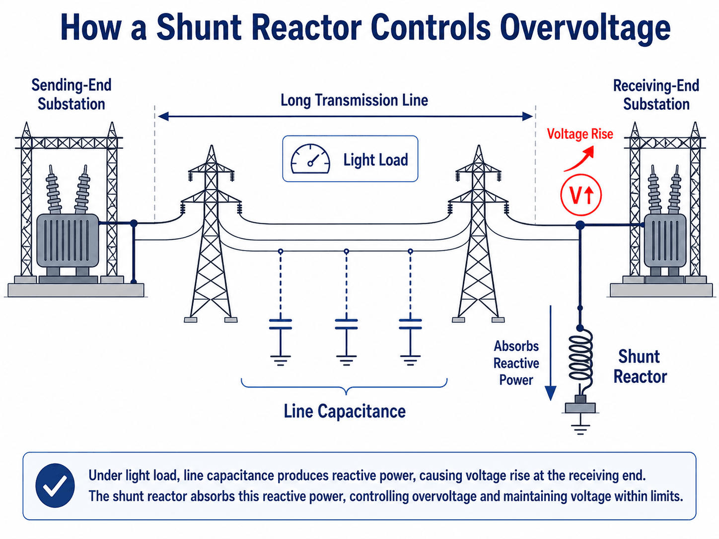
Transmission lines and underground cables have capacitance between conductors and from conductors to ground. When the line is lightly loaded, that capacitance can dominate the system behavior and raise the receiving-end voltage. This is why shunt reactors are often associated with high-voltage transmission lines, long cable circuits, and weak-grid operating conditions.
What the shunt reactor changes
The reactor provides an inductive path that consumes reactive power. In simplified terms, it offsets some of the capacitive vars produced by the line or cable. In real power system studies, engineers check voltage profiles, switching conditions, insulation stress, breaker duty, and whether a fixed, switched, or controlled reactor is appropriate.
A shunt reactor can improve light-load voltage, but it can also absorb vars when they are needed. Fixed reactors, switched reactors, and controlled reactors must be evaluated against actual operating cases rather than only the worst overvoltage case.
How Series Reactors Limit Fault Current
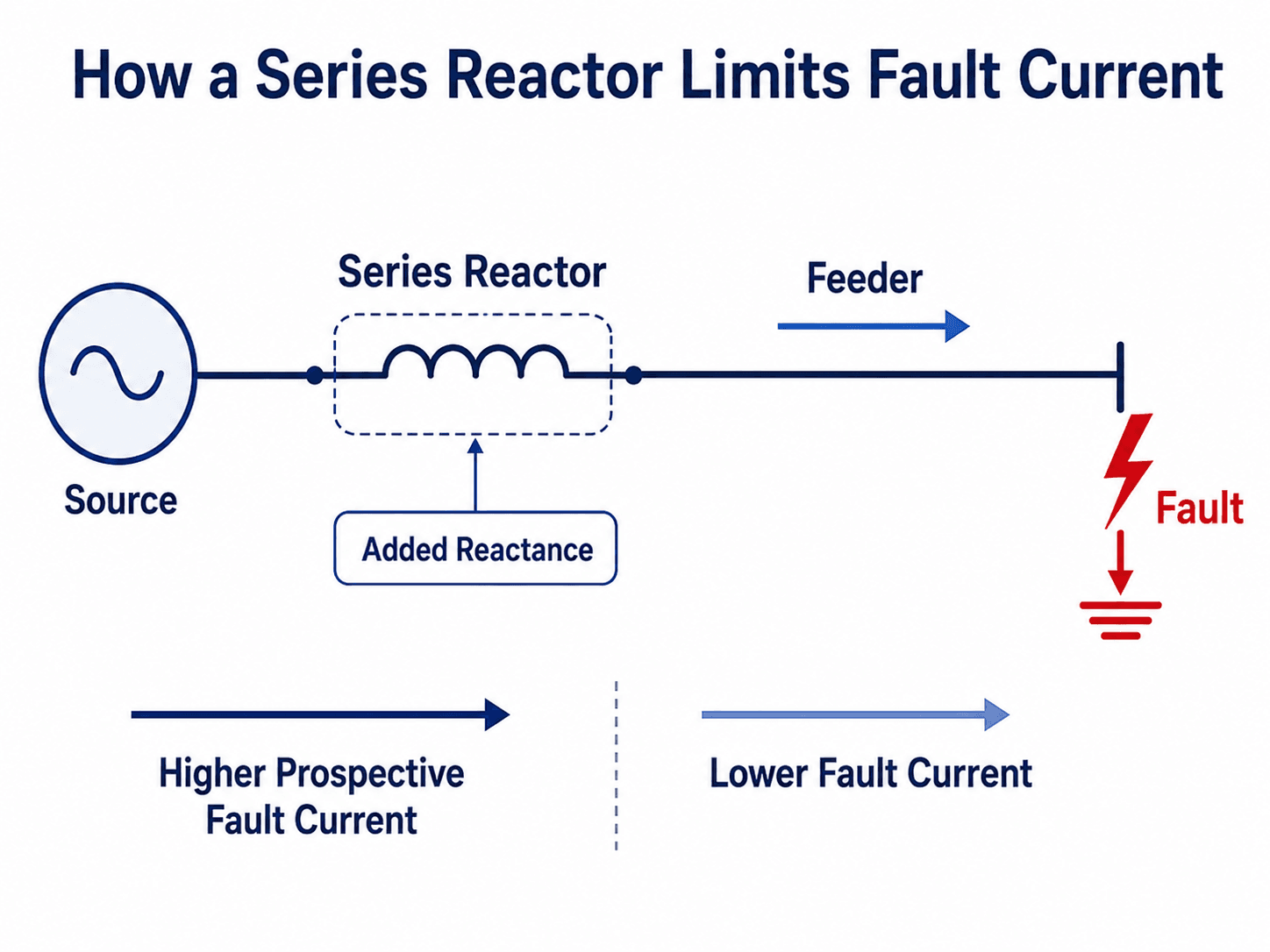
A series reactor is installed directly in the current path. Instead of connecting from the system to ground, it sits between the source and the downstream circuit. Its added reactance increases impedance, which can reduce the magnitude of current during a short circuit or switching event.
The protection benefit
Series reactors can help when available fault current is higher than the interrupting rating of existing breakers, fuses, bus equipment, or downstream switchgear. They are also used in some systems to reduce capacitor bank switching currents or to manage current sharing between parallel circuits.
The normal-operation tradeoff
The added reactance is present during normal operation, not only during faults. That means a series reactor can create voltage drop, affect motor starting, shift load flow, change relay reach, and alter coordination margins. This is why current-limiting benefits must be checked together with voltage regulation and protection settings.
Common Types of Reactors in Power Systems
Reactor terminology is often based on where the reactor is connected or what problem it solves. The table below separates the most common power system reactor applications so the word reactor does not become too generic.
| Reactor type | Typical connection | Main purpose | Practical caution |
|---|---|---|---|
| Shunt reactor | Parallel with bus, line, cable, or tertiary winding | Absorbs reactive power and controls overvoltage | Can reduce voltage support if left connected during high-load conditions. |
| Series reactor | In line with feeder, bus section, or circuit | Adds impedance and limits current | Creates normal-load voltage drop and changes protection behavior. |
| Current-limiting reactor | Usually series-connected | Reduces available short-circuit current | Must be checked against breaker ratings, relay settings, and thermal duty. |
| Capacitor bank reactor | Series with capacitor bank | Limits switching transients or helps tune harmonic behavior | Can interact with system harmonics if tuning is not reviewed. |
| Neutral grounding reactor | Between neutral and ground | Limits ground-fault current | Must still allow reliable detection and selective protection operation. |
| Filter reactor | Part of tuned filter branch | Controls frequency-dependent impedance with capacitors | Requires harmonic study and thermal review for non-fundamental currents. |
Shunt reactor vs capacitor bank
Reactors and capacitors are often discussed together because both affect reactive power, but they move the system in opposite directions. A shunt reactor absorbs reactive power, while a capacitor bank supplies reactive power. That difference matters for capacitor applications, voltage support, and overvoltage control.
| Device | Reactive power behavior | Typical system use |
|---|---|---|
| Shunt reactor | Absorbs reactive power | Controls overvoltage during light-load, long-line, or cable-dominated operating conditions. |
| Capacitor bank | Supplies reactive power | Supports voltage and power factor when inductive loads are consuming reactive power. |
| Filter reactor with capacitor | Creates frequency-dependent behavior | Supports tuned filtering, harmonic control, or controlled reactive compensation. |
Where Reactors Are Installed in a Power System
Reactor location is not just a layout decision. It determines which voltage problem is corrected, which fault current is limited, which breaker sees the switching duty, and which relays need to be reviewed. A reactor in the wrong location may have little effect on the target problem while creating new operating constraints.
| Installation location | Common reactor use | What engineers review |
|---|---|---|
| Transmission line terminal | Shunt reactor for long-line or cable charging compensation | Light-load voltage, switching state, breaker duty, and insulation coordination. |
| Substation bus | Shunt reactor or bus-connected reactive power device | System voltage profile, breaker arrangement, switching sequence, and grounding. |
| Transformer tertiary winding | Shunt reactor connected at a tertiary voltage level | Transformer rating, tertiary loading, protection zones, and grounding method. |
| Distribution feeder | Series or current-limiting reactor | Voltage drop, motor starting, feeder protection, and available fault current. |
| Capacitor bank branch | Series reactor for inrush limiting or harmonic tuning | Transient current, harmonic resonance, capacitor duty, and thermal current. |
| Neutral grounding point | Neutral grounding reactor | Ground-fault current level, detection sensitivity, insulation stress, and protection selectivity. |
In a substation, the physical location also affects clearances, foundations, maintenance access, noise exposure, bus arrangement, and how the reactor is isolated for maintenance.
Air-Core vs Iron-Core Reactors
Reactor construction affects saturation behavior, footprint, losses, noise, cooling, maintenance, and installation constraints. Many users first notice the difference visually: some reactors look like large open coils, while others look more like tanked or enclosed equipment.
| Construction type | Best fit | Main advantage | What to watch |
|---|---|---|---|
| Air-core reactor | Current limiting, capacitor banks, filter branches, and many outdoor MV/HV applications | No magnetic core saturation and relatively predictable inductance | Magnetic clearances, audible noise, footprint, support structure, and induced heating in nearby conductive loops. |
| Iron-core reactor | Applications where a compact magnetic-core design is appropriate | Can reduce size for a given inductance and rating | Core saturation, losses, heating, noise, and nonlinear behavior under abnormal conditions. |
| Dry-type reactor | Indoor or outdoor applications depending on enclosure, insulation, and environment | Avoids oil containment and can be simpler to inspect visually | Cooling, contamination, creepage, clearances, and environmental exposure. |
| Oil-immersed reactor | High-voltage utility applications or designs needing oil insulation and cooling | Strong insulation and cooling performance for suitable applications | Oil containment, maintenance, fire protection, environmental controls, and bushing condition. |
Air-core reactors need special attention around metallic structures, fences, reinforcing steel, cable trays, and closed conductive loops. The electrical rating may be correct, but the physical layout can still create heating or clearance problems.
Reactor Ratings and Nameplate Terms
Reactor ratings translate the system study into equipment requirements. A useful specification does not only say “install a reactor.” It defines the voltage class, current or Mvar duty, reactance, insulation level, thermal requirements, short-time current duty, and installation environment.
| Rating or term | What it means | Why it matters |
|---|---|---|
| Rated voltage | The system voltage class and insulation basis for the reactor | Controls insulation design, clearances, bushings, switching stress, and coordination with connected equipment. |
| Rated current | The continuous or duty-based current the reactor can carry | Critical for series reactors, capacitor bank reactors, and filter reactors where current flows through the device. |
| Mvar rating | Reactive power absorption rating, usually for shunt reactors | Determines how much capacitive reactive power the reactor can offset at rated voltage. |
| Reactance or impedance | The inductive opposition to AC current at rated frequency | Controls fault-current reduction, voltage drop, reactive power behavior, and filter tuning. |
| Rated frequency | The 50 Hz or 60 Hz basis for the rating | Reactance depends on frequency, and harmonic currents see different reactance than fundamental current. |
| BIL or insulation withstand | Ability to withstand lightning and switching surge stresses | Important for transmission, substation, and switching applications. |
| Thermal class or temperature rise | Heating limit under rated and specified duty conditions | Affects continuous operation, overload capability, insulation life, and maintenance intervals. |
| Short-time current rating | Ability to withstand fault current for a defined duration | Ensures the reactor survives mechanical and thermal stress during faults until protection clears. |
Nameplate terms should be reviewed with the study model. If a study uses per-unit impedance, ohms, percent reactance, or Mvar, engineers must confirm the voltage base, frequency base, and three-phase basis before comparing values directly.
Basic Reactor Equations Engineers Should Understand
Reactor studies can become detailed, but three relationships help explain the physical behavior. They are useful for learning and rough interpretation, not for replacing formal load-flow, short-circuit, transient, harmonic, or insulation coordination studies.
Inductive reactance \(X_L\) increases with frequency \(f\) and inductance \(L\). At 50 Hz or 60 Hz, that reactance is what lets a reactor absorb reactive power or oppose current. At harmonic frequencies, the reactor reactance changes, which is why filter and capacitor bank applications require frequency-aware review.
For a simplified shunt reactor concept, reactive power absorption increases with voltage and decreases as reactance increases. In three-phase applications, engineers must use the correct phase-voltage or line-to-line voltage basis and should verify the result against the manufacturer’s Mvar rating and the system study model.
For a simplified series reactor concept, voltage drop increases as current and reactance increase. Actual AC voltage regulation impact is phasor-based and depends on load current, power factor, system impedance, and where the reactor is installed.
- \(X_L\) Inductive reactance, usually in ohms. This is the main impedance effect a reactor adds to the system.
- \(f\) System frequency, typically 50 Hz or 60 Hz depending on the grid.
- \(L\) Inductance, usually in henries or millihenries for reactor applications.
- \(Q\) Reactive power, commonly expressed in kvar or Mvar for power system equipment.
- \(I\) Current through a series reactor, often evaluated for normal load, short-circuit duty, or switching transient duty.
Reactor Selection Workflow
Reactor selection starts with the system behavior that needs to change. The equipment rating should come after the system studies, not before. A reactor that looks correct from a single calculation can still be wrong if it creates unacceptable voltage drop, harmonic resonance, switching stress, or protection miscoordination.
Identify the system issue, select the reactor connection type, model the relevant operating cases, define the preliminary rating, check protection and switching impacts, verify installation constraints, and then confirm that the reactor solves the original problem without creating a new one.
| Workflow step | What to review | Common output |
|---|---|---|
| Define the problem | Overvoltage, excessive fault current, inrush, grounding, harmonics, or reactive power imbalance | Clear design objective and reactor application type |
| Choose connection type | Shunt, series, neutral grounding, capacitor bank, or filter branch | One-line diagram location and switching arrangement |
| Model study cases | Light load, peak load, contingency, switching, fault, and abnormal source configurations | Voltage, current, reactive power, and fault-duty results |
| Define preliminary rating | Mvar, reactance, voltage, current, frequency, insulation, and thermal duty | Equipment specification range |
| Check protection impact | Relay pickup, reach, sensitivity, selectivity, and backup coordination | Protection setting revisions or design constraints |
| Check switching and transients | Breaker TRV, energization, de-energization, restrike risk, and capacitor bank interaction | Switching duty confirmation and surge mitigation needs |
| Verify physical installation | Clearances, magnetic fields, noise, ventilation, foundations, seismic support, and access | Substation layout and constructability requirements |
Senior Engineer Review Checklist for Reactor Applications
Reactor applications are study-driven. A good review does not stop at “add reactance.” It checks whether the reactor solves the original problem without creating a worse voltage, protection, switching, thermal, or installation issue.
| Review item | What to look for | Why it matters |
|---|---|---|
| System problem definition | Overvoltage, excessive fault current, capacitor switching, grounding, or harmonic issue. | The correct reactor type depends on the problem being solved. |
| Connection method | Shunt, series, neutral grounding, capacitor bank, or filter branch connection. | Connection changes the entire system effect of the reactor. |
| Load-flow impact | Voltage profile, reactive power balance, switching states, and light-load versus peak-load cases. | A shunt reactor can correct overvoltage in one case and reduce useful voltage support in another. |
| Short-circuit impact | Available fault current, breaker interrupting duty, momentary duty, and downstream equipment ratings. | A series reactor may reduce fault current enough to avoid major equipment replacement. |
| Protection coordination | Relay pickup, time-current curves, distance elements, differential zones, and backup protection. | Added impedance can change relay sensitivity, selectivity, and apparent fault location. |
| Switching and transient duty | Breaker TRV, restrike risk, insulation stress, energization transients, and capacitor-bank interaction. | Reactors can improve one transient problem while introducing another if switching duty is ignored. |
| Installation constraints | Clearance, magnetic fields, audible noise, ventilation, foundations, seismic support, and maintenance access. | Large reactors are physical substation assets, not just symbols on a one-line diagram. |
Engineering Judgment and Field Reality
On a one-line diagram, a reactor may look like a simple coil. In the field, it is a large electrical asset with insulation requirements, thermal limits, magnetic clearances, support structure, grounding details, switching behavior, audible noise, and protection implications.
Reactor placement is especially important. A shunt reactor on a transmission line may be installed at a line terminal, bus, or transformer tertiary. A series reactor may be installed on a feeder, bus tie, capacitor bank, or source path. Each location changes which equipment sees the reactor, which faults are limited, and which relays need review.
Switching and transient issues
Reactors can affect breaker transient recovery voltage, restrike behavior, chopping effects, energization transients, and surge arrester duty. These issues are especially important for shunt reactor switching, capacitor bank reactor applications, and high-voltage substations where insulation stress controls equipment selection.
Protection coordination effects
Added reactance changes available fault current and apparent impedance. That can affect overcurrent protection, distance elements, differential zones, backup protection, and fuse coordination. A reactor should be reflected in the protection model, not just the load-flow model.
Maintenance and inspection reality
Practical inspection depends on construction type, but common review points include insulation condition, support hardware, contamination, corrosion, overheating evidence, unusual noise, vibration, grounding integrity, bushing condition, and physical clearances around the reactor.
Reactors often solve a system-level problem but create local design responsibilities. The electrical study may justify the reactor, while the substation design still has to handle clearances, grounding, heat, noise, structure, switching equipment, and maintainability.
When This Breaks Down
The simplified idea that a reactor “absorbs vars” or “limits current” is useful for learning, but it breaks down when the system is evaluated across real operating cases. Reactors interact with the network, and that interaction can change with switching status, load level, source strength, frequency content, and protection settings.
- One operating case is not enough: A shunt reactor that controls light-load overvoltage may be undesirable during heavy load or low-voltage conditions.
- Fault-current reduction is not the only goal: A series reactor may reduce short-circuit current but also increase voltage drop and affect motor starting or feeder voltage.
- Harmonics can change the conclusion: Capacitor bank and filter reactor applications require frequency-domain thinking, not only 50 Hz or 60 Hz reactance.
- Protection may need new settings: A reactor can change apparent impedance, available fault current, and current distribution through parallel paths.
- Switching duty can control the design: Reactor energization, de-energization, and capacitor-bank interaction can create transient stresses that are not obvious from steady-state calculations.
Common Mistakes and Practical Checks
Most reactor mistakes come from treating the device as a generic inductor instead of a system-level component. The symbol is simple, but the application affects voltage, current, protection, switching, insulation, and equipment layout.
- Confusing shunt and series behavior: A shunt reactor and a series reactor both use inductance, but their system effects are very different.
- Ignoring voltage drop: A current-limiting reactor may solve a fault-duty problem while creating unacceptable load voltage drop.
- Assuming Mvar rating alone is enough: Shunt reactor application also depends on voltage level, location, switching cases, insulation duty, and system operating conditions.
- Forgetting protection coordination: Added impedance can reduce fault current below expected relay sensitivity or shift coordination margins.
- Skipping physical installation checks: Air-core reactors can require magnetic clearances and careful layout to avoid heating nearby conductive loops or structures.
Do not select a reactor only from the problem name. “Overvoltage,” “fault current,” “capacitor switching,” and “grounding” each point to a different reactor application and a different study workflow.
Engineering References and Design Guidance
Reactor applications are commonly supported by manufacturer data, utility standards, protection studies, load-flow models, short-circuit studies, and project-specific specifications. Public technical references are most useful when they explain the engineering tradeoffs instead of only listing product options.
- Technical reference: GE Vernova technical whitepaper on air-core series reactors for fault-current reduction explains how series reactors can reduce short-circuit current and why the added reactance also affects continuous-operation voltage drop.
- Project-specific criteria: Utility standards, owner specifications, equipment ratings, protection philosophy, and substation layout requirements usually control the final reactor application.
- Engineering use: Engineers typically combine equipment data with load-flow, short-circuit, transient, harmonic, insulation coordination, and protection coordination studies before finalizing reactor size and location.
Frequently Asked Questions
A reactor in a power system is an inductive device used to add reactance to the network. Depending on how it is connected, it can absorb reactive power, control overvoltage, limit fault current, reduce inrush effects, or support power quality and protection coordination.
A shunt reactor is connected in parallel with a bus, line, or cable system and is mainly used to absorb reactive power and control overvoltage. A series reactor is connected in line with a feeder, bus section, capacitor bank, or circuit and is mainly used to add impedance and limit current.
Long transmission lines and underground cables have capacitance that can generate reactive power, especially under light-load conditions. A shunt reactor absorbs some of that reactive power so the receiving-end voltage does not rise beyond acceptable operating limits.
A series reactor limits fault current by adding inductive reactance in the current path. The added impedance reduces the available short-circuit current downstream, but it can also create voltage drop during normal operation, so protection and voltage performance must be checked together.
A reactor is a type of inductor designed for power-system duty. Compared with a small electronics inductor, it is built for higher voltage, higher current, insulation withstand, thermal duty, mechanical forces, switching transients, and substation or industrial installation requirements.
Summary and Next Steps
Reactors are inductive devices used to intentionally change power system reactance. In shunt applications, they are most often associated with reactive power absorption and overvoltage control. In series applications, they are most often associated with added impedance, current limiting, and protection-related tradeoffs.
The most important engineering step is to connect the reactor application to the real system problem. Voltage rise, excessive fault current, capacitor switching, grounding, and harmonic filtering all require different checks. A good reactor review considers load flow, short-circuit duty, switching transients, protection coordination, equipment ratings, and physical installation constraints together.
Where to go next
Continue your learning path with related Turn2Engineering power systems resources.
-
Voltage Regulation
Learn how voltage is maintained as loads, reactive power, regulators, capacitors, and reactors change operating conditions.
-
Short-Circuit Analysis
Review how fault current is calculated and why current-limiting reactors may be considered when equipment duty is too high.
-
Substations
See how reactors fit into the broader substation environment with breakers, buses, transformers, protection, and switching equipment.