Key Takeaways
- Definition: Groundwater is subsurface water that fills soil or rock voids and directly affects pore pressure, seepage, uplift, and effective stress.
- Why it matters: The same soil can behave very differently above, near, or below the groundwater level because strength and compressibility depend on the stress carried by the soil skeleton.
- Main design question: Engineers must determine where water is, how it moves, how fast it changes, and whether the project alters drainage or pressure conditions.
- Practical outcome: A good groundwater evaluation improves excavation safety, foundation performance, retaining wall reliability, settlement estimates, and dewatering planning.
Table of Contents
Introduction
In brief: Groundwater is subsurface water that controls pore pressure and seepage, which in turn influence soil strength, settlement, uplift, and excavation stability.
Who it’s for: Students, FE/PE prep, and designers.
In geotechnical work, groundwater is rarely just a background condition. It is often one of the main things controlling whether a design is stable, buildable, and durable.
Groundwater infographic
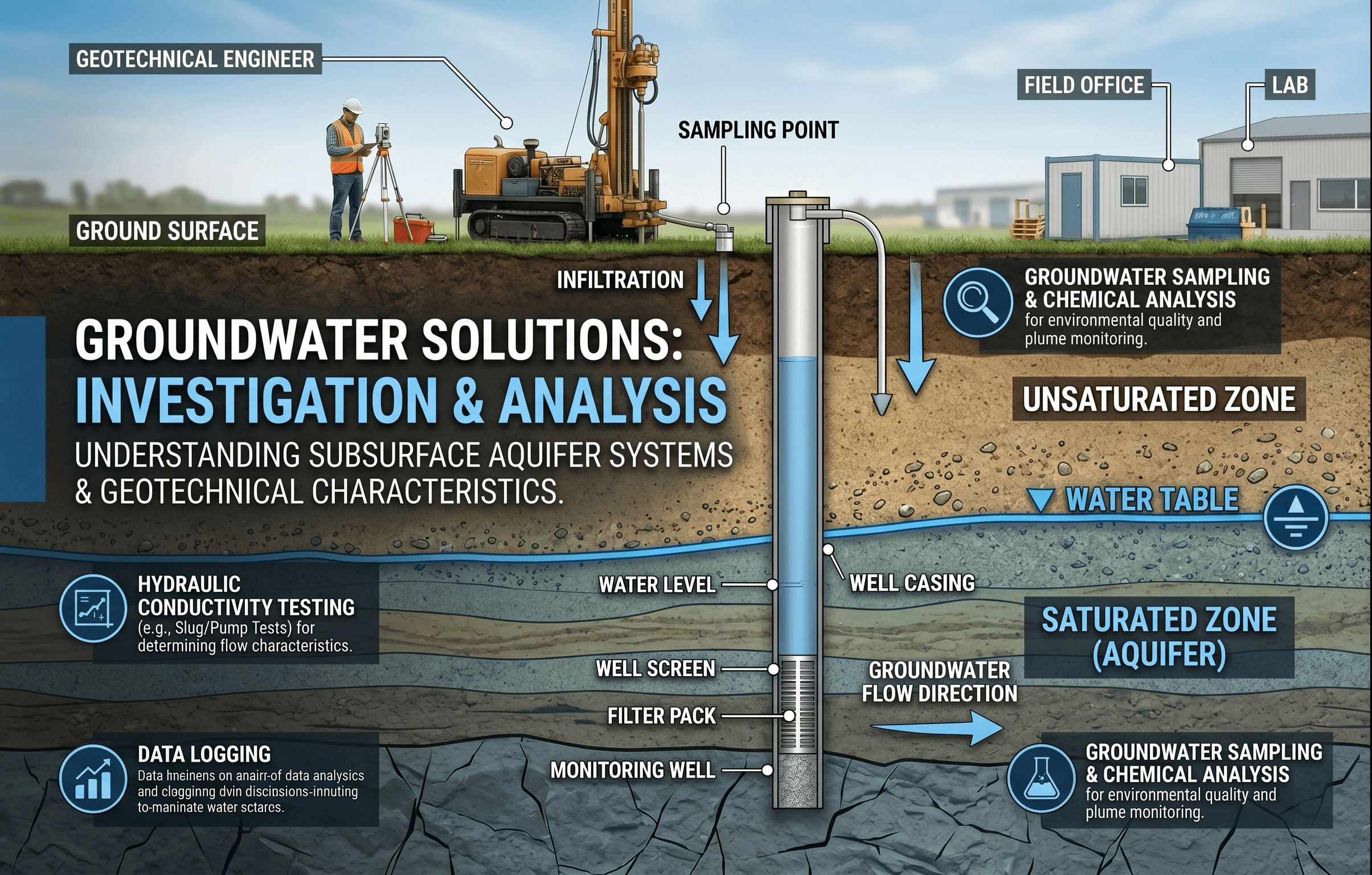
Notice that groundwater is not only about the elevation of a water table. The more important engineering question is how water pressure and flow interact with the soil skeleton, because that is what changes effective stress, seepage forces, and stability.
What is groundwater?
Groundwater is water stored below the ground surface in the interconnected voids of soil or rock. In geotechnical engineering, the topic matters because soil behavior depends not only on the particles themselves, but also on the water occupying the voids between them. When those voids are filled or partially filled with water, the resulting pore water pressures can reduce effective stress, change shear strength, increase uplift, trigger seepage, and alter settlement behavior.
Many people loosely use the phrase water table as if it fully describes groundwater conditions. That is useful as a starting point, but real projects are more complicated. A simple unconfined water table might exist in uniform sandy soil. In layered deposits, however, you may have perched water, delayed drainage, artesian pressure, or confined groundwater that does not behave like a single horizontal line. That is why groundwater evaluation is both a site characterization issue and a design issue.
Groundwater shows up in almost every major geotechnical task: shallow foundation design, pile design, slope stability, retaining wall drainage, excavation support, embankment performance, pavement subgrade behavior, and earth structure seepage control. If the soil is the framework, groundwater is often the variable that decides whether that framework acts stiff, weak, drained, buoyant, or unstable.
Core principles, variables, and units
The most important groundwater concepts in geotechnical engineering are hydraulic head, pore water pressure, permeability, hydraulic gradient, seepage direction, and effective stress. These are the quantities engineers use to move from “there is water on site” to “here is how that water changes design.”
Why effective stress is the real controlling idea
Total stress comes from the weight of soil, water, structures, and surcharges. Pore water pressure is the pressure carried by the water in the voids. Effective stress is the portion of the total stress carried by the soil skeleton. Since the soil skeleton resists deformation and provides most of the shear strength in ordinary geotechnical problems, effective stress is usually the quantity that controls performance.
Here, \( \sigma’ \) is effective stress, \( \sigma \) is total stress, and \( u \) is pore water pressure. If pore water pressure rises, effective stress drops. That usually means lower shear strength and a higher risk of instability. If drainage lowers pore pressures, effective stress rises and the ground can become stronger or settle further depending on the loading history.
Key variables and typical ranges
Groundwater calculations do not always need complicated models, but they do require disciplined units and realistic site assumptions. The quantities below are the ones you check first.
- \(u\) Pore water pressure, typically in kPa or psf. In static water, it increases approximately with depth below the phreatic surface.
- \(h\) Hydraulic head, usually in meters or feet of water. This is the energy level driving groundwater flow.
- \(i\) Hydraulic gradient, dimensionless. It is the head loss per unit flow length and is critical for seepage and piping checks.
- \(k\) Coefficient of permeability or hydraulic conductivity, often in m/s, cm/s, or ft/s. Sands are typically far more permeable than clays.
- \(Q\) Discharge or seepage flow rate, commonly in m³/s, ft³/s, L/s, or gpm depending on the project stage.
- \(\gamma_w\) Unit weight of water, commonly taken as about 9.81 kN/m³ or 62.4 pcf for many practical calculations.
When a geotechnical problem seems confusing, translate it into three questions: where is the water, where is it moving, and how does that movement change effective stress?
Decision logic or design workflow
A good groundwater review is a workflow, not a single input box on a report. Engineers first identify groundwater conditions, then determine whether the project changes those conditions, and finally decide which checks are controlled by water.
Step 1: Identify the groundwater regime from borings, wells, piezometers, site topography, drainage features, and seasonal history.
Step 2: Decide whether the problem is static or transient. Excavations, storms, pumping, and nearby drainage changes can make the groundwater condition time-dependent.
Step 3: Determine the design mechanism: bearing, settlement, seepage, uplift, heave, wall pressure, slope instability, pavement softening, or erosion.
Step 4: Use the simplest defensible model first, then upgrade to piezometric interpretation, seepage analysis, or staged construction review if assumptions are no longer reliable.
Step 5: Revisit construction sequencing. Temporary groundwater conditions during excavation can be more critical than final long-term conditions.
This workflow matters because many failures come from using one groundwater assumption for every phase of a project. Existing condition, during construction condition, and long-term post-construction condition may all be different.
Equations and calculations
The most common groundwater calculation in introductory geotechnical work is Darcy’s law, which relates flow rate to hydraulic conductivity, hydraulic gradient, and flow area.
In this equation, \(Q\) is flow rate, \(k\) is hydraulic conductivity, \(i\) is hydraulic gradient, and \(A\) is the flow area normal to flow. Darcy’s law is most reliable for laminar flow through porous media and is widely used for seepage estimates, preliminary dewatering checks, and flow-net interpretation.
Pore water pressure from depth below the water surface
For static groundwater in a connected water body, pore water pressure is commonly estimated as:
Here, \(z\) is the vertical depth below the groundwater surface measured in the direction of gravity. This is simple hydrostatics, but it only applies directly where water is not flowing in a way that changes the pressure distribution significantly.
Why these equations are useful together
Hydrostatic pressure tells you what the pore pressures look like when water is at rest. Darcy’s law tells you how water moves when a head difference exists. In geotechnical design, both matter because pore pressure affects strength and deformation, while seepage affects erosion, uplift, and internal stability.
Worked example
Example: seepage estimate through a sandy layer below an excavation
Suppose an excavation is supported in granular soil, and a simplified seepage check is needed for preliminary dewatering planning. Assume the hydraulic conductivity of the sand is \(k = 2 \times 10^{-4}\) m/s, the head difference across the flow path is 2.4 m, the representative seepage path length is 12 m, and the effective cross-sectional area normal to flow is 18 m².
First compute the hydraulic gradient:
Now apply Darcy’s law:
This is about 0.72 L/s. On its own, that number does not tell you whether the system is safe. The real engineering value comes from interpretation: is the inflow localized or distributed, does it increase near corners or low-permeability boundaries, can the base remain stable, and does pumping change the stress state enough to cause settlement outside the excavation? That is why groundwater examples should always end with a design judgment, not just a number.
Engineering judgment and field reality
Groundwater data is often messier than geotechnical reports make it look. A boring log may show “water encountered at 11 ft” and “water stabilized at 14 ft,” but that does not necessarily define a permanent water table. Drilling methods disturb the ground, seasonal conditions matter, and low-permeability soils may need significant time before pressures equalize. In layered profiles, a short-term field observation can miss perched water or artesian pressure entirely.
Construction also changes groundwater conditions. Excavation opens new drainage boundaries. Sumps and pumps lower local heads. Retaining systems interrupt flow paths. Fill placement changes recharge and runoff. A project can therefore create a groundwater problem even when the site investigation only showed a mild one.
Experienced engineers also separate groundwater elevation from groundwater behavior. The important question is not just “how deep is water?” but “what pressure exists here, what direction is it trying to move, and what happens if the contractor cuts, pumps, or drains this area?” That mindset prevents many avoidable mistakes.
If a project is sensitive to uplift, heave, piping, or soft subgrades, one groundwater measurement during drilling is rarely enough. Piezometers and time-based readings often provide the information that actually controls the design.
When this breaks down
Simple groundwater methods break down when the site no longer behaves like a uniform, steady-state flow problem. Confined aquifers, interbedded silts and sands, fissured clays, fractured rock, partial saturation, strong anisotropy, recharge from utilities or storm events, and rapidly changing pumping conditions can all invalidate a one-line calculation or a single assumed water table.
Darcy-based estimates also need caution if the assumed flow area is poorly defined, if the hydraulic conductivity varies by orders of magnitude across the profile, or if local gradients become steep enough to raise piping or boiling concerns. Likewise, hydrostatic pressure assumptions do not represent seepage-induced excess pressure distributions near drains, cutoffs, wells, or uplift-sensitive slabs.
The practical signal that your method is breaking down is usually this: the answer becomes highly sensitive to assumptions you cannot defend with field evidence. When that happens, the next step is not to keep refining the algebra. The next step is to improve the groundwater model with better instrumentation, staged observations, or more appropriate seepage analysis.
Common pitfalls and engineering checks
- Assuming one groundwater elevation applies across the whole site despite topography, drainage ditches, or layered soils.
- Using total stress thinking when the real problem is controlled by effective stress.
- Ignoring temporary construction groundwater conditions and checking only the final condition.
- Confusing seepage inflow quantity with stability; low flow can still produce critical uplift or piping risk at a local point.
- Using representative hydraulic conductivity values without considering whether vertical and horizontal permeability differ significantly.
One of the most expensive errors in geotechnical work is treating groundwater as a note on a boring log instead of a design variable. That often leads to missed dewatering needs, underpredicted settlement, and unstable excavation bottoms.
Always ask whether the chosen groundwater condition is conservative for the mechanism being checked. A high water level may control uplift and stability, while a lowered water level after pumping may control settlement outside the excavation.
| Parameter | Symbol | Typical units | Why it matters |
|---|---|---|---|
| Pore water pressure | \(u\) | kPa, psf | Directly affects effective stress and therefore shear strength and deformation. |
| Hydraulic conductivity | \(k\) | m/s, ft/s | Controls how quickly groundwater can move through soil. |
| Hydraulic gradient | \(i\) | dimensionless | Helps assess seepage forces, inflow, and piping susceptibility. |
| Groundwater elevation | — | m, ft | Defines reference conditions for hydrostatic pressure and drainage assumptions. |
| Unit weight of water | \(\gamma_w\) | kN/m³, pcf | Used to convert depth or head to pore water pressure and uplift force. |
Visualizing groundwater in practice
A useful mental sketch is a layered soil profile with a footing, a retaining wall, and an excavation cut. Draw the water table first, then add arrows showing seepage direction, then identify the zones where pore pressure lowers effective stress. That simple sequence often reveals which part of the project is actually groundwater-controlled.
For example, under a retaining wall, groundwater may increase lateral pressures if drainage is poor. Under a footing, elevated pore pressure can reduce effective stress and change settlement behavior. In an excavation, upward gradients can trigger instability even before visible inflow becomes dramatic.
The goal is not just to picture water present in the ground, but to picture how pressure and flow interact with the soil skeleton and the structure.
Relevant standards and design references
Groundwater design checks are usually project-specific, but several standard references help govern testing, seepage interpretation, and geotechnical decision-making.
- ASTM D2434: Covers permeability testing of granular soils using a constant-head approach. It is commonly used when seepage behavior in sands is central to design.
- ASTM D5084: Covers measurement of hydraulic conductivity in saturated porous materials using a flexible wall permeameter. This is important for lower-permeability soils and barrier or liner-related work.
- ASTM D1586: The Standard Penetration Test does not measure groundwater directly, but boring logs and sampling programs are often interpreted together with groundwater observations during subsurface exploration.
- USACE, FHWA, and local DOT geotechnical manuals: These commonly provide guidance on seepage, dewatering, embankments, retaining systems, and instrumentation requirements.
- Project-specific drainage and excavation support criteria: Many groundwater decisions are governed by temporary works requirements, risk tolerance, and local agency expectations rather than a single universal code clause.
Frequently asked questions
Groundwater level is the observed elevation of water in a well or piezometer, while pore water pressure is the pressure at a specific point in the soil mass. In simple hydrostatic conditions they relate closely, but layered soils, confined conditions, and seepage can make the pressure distribution much different from a single water table assumption.
Groundwater affects effective stress, seepage, uplift, consolidation, excavation stability, and subgrade performance. Because those mechanisms control strength and movement, groundwater often changes the governing design condition more than the soil classification alone.
They break down in layered deposits, transient drainage conditions, confined aquifers, artesian pressures, partially saturated soils, and pumped excavations. If the answer changes drastically when you move the assumed water level or hydraulic conductivity, the problem likely needs better field data or a better seepage model.
It shows up in foundation bearing and settlement checks, retaining wall drainage, slope stability, excavation support, embankment performance, pavement softening, and seepage control for earth structures. In practice, groundwater is often the condition that decides whether a design is easy to build or difficult to build safely.
Summary and next steps
Groundwater is the subsurface water condition that drives pore pressure and seepage, and those two ideas strongly influence geotechnical performance. Once you connect groundwater to effective stress, the subject becomes much more practical: strength, settlement, uplift, flow, and stability all start to make sense within one framework.
For real projects, the most useful habit is to stop thinking of groundwater as a single line on a boring log. Instead, treat it as a system with location, pressure, direction, and time dependence. That approach leads to better field investigations, safer construction planning, and more reliable designs.
The next step is usually to connect groundwater behavior to a specific geotechnical application, such as seepage, foundations, retaining systems, or slope stability. That is where the theory starts paying off.
Where to go next
Continue your learning path with these curated next steps.
-
Read a deeper dive on Foundation Design
Groundwater directly changes bearing, settlement, uplift, and construction sequencing for foundations.
-
Study Slope Stability
A strong next step if you want to see how pore pressure and seepage influence factors of safety in earth slopes.
-
Review Earth Retaining Structures
Useful for understanding drainage, hydrostatic pressure, and wall performance under groundwater loading.