
Key Takeaways
- Core idea: A truss system uses straight members and triangular geometry to move loads through axial tension and compression instead of relying primarily on bending.
- Engineering use: Trusses are common in roofs, bridges, floor systems, towers, transfer structures, industrial buildings, and long-span framing where material efficiency matters.
- What controls it: Geometry, support conditions, load locations, member slenderness, connections, bracing, deflection, and construction-stage stability all affect performance.
- Practical check: A truss is not just a pattern of triangles; it is a complete load path that depends on reliable joints, lateral restraint, bearing, and field installation.
Table of Contents
Introduction
Truss systems are structural frameworks made from straight members connected at joints, usually forming triangular units that carry loads mainly through axial tension and compression. They matter because they can span long distances with less material than many solid framing options, but only when the geometry, members, connections, supports, and bracing work together as one load path.
Visual Guide to How Truss Systems Carry Load
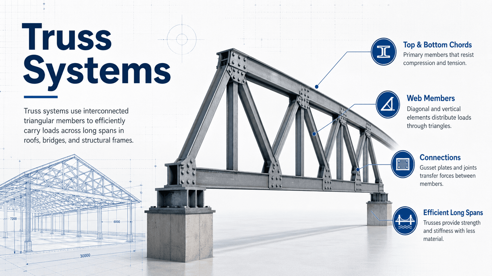
Notice that the important feature is not simply the triangular shape. The load must enter the truss at appropriate points, the members must have enough strength and stiffness, and the supports must provide a continuous path into the rest of the structure.
What is a Truss System?
A truss system is an assembly of straight structural members connected at joints to form a stable framework. In ideal truss behavior, each member acts mostly as a two-force member, meaning the member is primarily pulled in tension or pushed in compression along its length. This is different from a beam, where bending and shear usually dominate.
The reason trusses are so useful in structural engineering is that axial forces can be efficient. A well-proportioned steel, timber, or wood truss can cross a large opening while using less material depth and weight than a comparable solid beam. The tradeoff is that the system becomes more sensitive to connection quality, bracing, load placement, and member buckling.
A truss should be understood as a force-transfer system, not just a shape. The triangles provide stability, but the engineering performance comes from the complete path from applied load to member forces to support reactions.
How Truss Systems Work
Trusses work by converting a distributed structural demand into a pattern of axial forces. Under gravity loading, the top chord of a roof or bridge truss often experiences compression, the bottom chord often experiences tension, and the diagonal or vertical web members redirect force between the chords and supports. The exact pattern depends on geometry, loading, support conditions, and truss type.
Triangulation creates geometric stability
A rectangle can distort into a parallelogram without changing the length of its sides. A triangle cannot change shape unless one of its sides changes length or a connection fails. This is why trusses use repeated triangular panels: the geometry helps the structure resist shape change while allowing individual members to work mainly along their length.
Panel points control how loads enter the truss
The cleanest truss behavior occurs when major loads are applied at panel points, where members meet. If a heavy load is applied between panel points, the chord member may also experience bending. That does not automatically make the design wrong, but it means the member and connection assumptions must reflect the actual load path rather than an ideal textbook model.
Connections make the force path real
A truss diagram usually shows simple lines meeting at joints, but the built structure relies on gusset plates, welds, bolts, connector plates, timber fasteners, bearing seats, and bracing details. If the connection cannot transfer the force assumed in analysis, the member layout alone will not protect the structure.
Main Parts of a Truss System
Understanding truss terminology makes it easier to read drawings, compare truss types, and follow the load path. The same terms appear in roof trusses, bridge trusses, floor trusses, and long-span building trusses, even though the materials and details may differ.
| Component | What it does | Practical note |
|---|---|---|
| Top chord | Forms the upper boundary of the truss and often carries compression under gravity loading. | Frequently controlled by buckling and lateral restraint. |
| Bottom chord | Forms the lower boundary and often carries tension under gravity loading. | May control ceiling support, tie force, service routing, or uplift reversal. |
| Web members | Diagonal and vertical members that transfer force between the chords. | Their tension or compression role changes with truss type and load case. |
| Panel points | Joints where members connect and where ideal truss loads are commonly introduced. | Misplaced loads can introduce bending that was not intended in simplified analysis. |
| Bearings and supports | Transfer reactions from the truss into walls, beams, columns, piers, or foundations. | Bearing length, anchorage, uplift, and support movement must be considered. |
| Lateral bracing | Restrains members and the truss system from out-of-plane movement. | Often essential for compression chord and web stability. |
| Gusset or connector plates | Transfer force between members at the joint. | Connection behavior often controls real-world truss performance. |
Common Types of Truss Systems
Different truss layouts are used because load direction, span length, material, fabrication method, architectural depth, and service requirements are not the same on every project. A roof truss, bridge truss, floor truss, and tower truss may all use triangles, but they solve different problems.
| Truss type | Common use | Main advantage | Watch for |
|---|---|---|---|
| Pratt truss | Bridges, long-span roofs, steel framing | Diagonals often work efficiently in tension under gravity loading. | Force reversal can occur under wind, moving loads, or uplift. |
| Warren truss | Bridges, roof framing, simple long spans | Repeating triangular pattern distributes forces efficiently. | Concentrated loads may require verticals or local chord bending checks. |
| Howe truss | Timber bridges, roof systems, historic structures | Can place timber-friendly members in compression depending on layout. | May be less efficient than Pratt-style layouts for some steel applications. |
| Fink truss | Residential and light commercial pitched roofs | Efficient roof geometry with short web members. | Attic space and mechanical routing may be limited. |
| Scissor truss | Vaulted ceilings and architectural roof framing | Creates interior ceiling slope while maintaining truss action. | Deflection, thrust effects, and bearing details need careful review. |
| King post or queen post | Short to moderate spans, timber framing, simple roofs | Simple geometry and clear load path. | Limited span efficiency compared with deeper or more subdivided trusses. |
| Open-web floor truss | Floor framing with mechanical, electrical, or plumbing runs | Allows services to pass through the structural depth. | Vibration, deflection, and web damage during trade work must be controlled. |
| Space truss | Large roofs, towers, canopies, 3D structural grids | Provides stiffness in multiple directions. | Connection complexity and erection sequencing become more important. |
Where Truss Systems Are Used in Structural Engineering
Engineers choose trusses when the structure needs span, depth efficiency, material economy, repeatable fabrication, or open space between members. The same structural idea appears in many project types, but the controlling design issue changes with the application.
- Roof trusses: Common in residential, commercial, industrial, and agricultural buildings where repetitive fabrication and predictable roof geometry reduce framing complexity.
- Bridge trusses: Useful for carrying deck loads across long spans while maintaining a visible and efficient load path between supports.
- Floor trusses: Often selected when open webs help route ducts, pipes, and electrical systems through the floor depth.
- Towers and masts: Use three-dimensional triangulation to resist wind and gravity loads in slender structures.
- Long-span buildings: Used in gyms, warehouses, hangars, arenas, and industrial structures where columns are undesirable within the occupied space.
Before selecting a truss type, ask what controls the project: span, available depth, load location, fabrication cost, exposed appearance, service routing, fire protection, corrosion protection, vibration, erection access, or future maintenance.
What Controls Truss System Performance?
The performance of a truss system is controlled by more than member strength. A truss can have strong individual members and still perform poorly if the load path is interrupted, the compression members are unbraced, the supports move unexpectedly, or the connections do not match the analysis assumptions.
| Factor | Why it matters | Engineering implication |
|---|---|---|
| Span and depth | Depth strongly affects member forces and deflection. | A deeper truss can often reduce chord force, but may conflict with architecture, clearance, or transportation limits. |
| Load placement | Ideal truss behavior assumes major loads enter at joints. | Loads between panel points can introduce chord bending and require additional design checks. |
| Member slenderness | Compression members may buckle before material strength is reached. | Unbraced length, radius of gyration, and end restraint can control member sizing. |
| Connection behavior | Joints transfer force between members and can govern capacity. | Bolts, welds, gusset plates, connector plates, and timber fasteners must match the expected force path. |
| Lateral bracing | Trusses are often strong in their own plane but vulnerable out of plane. | Compression chords and webs may need continuous restraint, cross-bracing, blocking, or diaphragm action. |
| Serviceability | Strength is not the only performance limit. | Deflection, vibration, ponding, ceiling cracking, and façade movement can control design. |
| Construction stage | A partially braced truss may not behave like the completed structure. | Temporary bracing, lift points, erection sequencing, and stability during installation must be planned. |
Basic Truss Analysis Methods
Truss analysis starts by identifying loads, supports, geometry, and joints. For simple planar trusses, engineers and students often use equilibrium-based methods before moving to computer models. For real projects, software may be used, but the model still needs a rational load path and realistic assumptions.
For a simple, stable, statically determinate planar truss, the number of members \(m\) plus the number of reaction components \(r\) often equals twice the number of joints \(j\). This check does not prove that a truss is properly detailed, but it is a useful first screen for simple textbook-style trusses.
- m Number of truss members in the planar model.
- r Number of external support reaction components.
- j Number of joints or panel points in the idealized truss model.
Method of joints
The method of joints isolates one joint at a time and applies force equilibrium in two directions. It is useful when the goal is to solve member forces throughout the truss, especially when starting from a support or a joint with only a few unknown member forces.
Method of sections
The method of sections cuts through the truss and uses equilibrium of one side of the cut. It is useful when only a few member forces are needed, such as checking the chord and diagonal forces at a critical panel near midspan.
Zero-force members
Some members may carry no force under a specific load case, but that does not always mean they are unnecessary. They may help with stability, fabrication, bracing, construction loads, alternate load patterns, or force reversal under wind and seismic effects.
Truss System Selection Guide
A good truss selection process starts with the structural job the system must perform. The “best” truss is not the one with the most triangles; it is the one that satisfies span, load path, depth, fabrication, constructability, serviceability, and inspection needs with the least unnecessary complexity.
Start with the span and available depth. Identify where loads enter the system. Choose a truss geometry that keeps forces mostly axial. Check compression members for buckling, confirm bracing requirements, size connections, review deflection and vibration, then verify how the truss will be shipped, lifted, installed, and inspected.
| Project need | Likely truss direction | What to verify |
|---|---|---|
| Simple residential roof | Fink, king post, queen post, or attic truss depending on span and room needs. | Bearing, uplift, permanent bracing, mechanical conflicts, and whether any field modifications are proposed. |
| Vaulted ceiling | Scissor truss or custom roof truss. | Deflection, thrust behavior, heel detail, insulation depth, and ceiling finish sensitivity. |
| Bridge or pedestrian span | Pratt, Warren, Howe, K, pony, through, or deck truss depending on span and clearance. | Moving loads, fatigue, lateral bracing, deck connection, corrosion, and inspection access. |
| Open mechanical routing through a floor | Open-web floor truss. | Service penetrations, vibration, deflection, fire rating, and web member protection during construction. |
| Large column-free roof area | Steel roof truss, space truss, bowstring truss, or long-span open-web system. | Roof diaphragm interaction, erection stability, camber, ponding, snow drift, and connection detailing. |
| Slender tower or mast | Three-dimensional lattice or space truss system. | Wind loading, torsion, foundation reactions, member slenderness, and connection fatigue. |
Example: Reading a Simple Roof Truss Load Path
Consider a pitched roof truss supporting roof sheathing, roofing material, snow, wind uplift, and ceiling load. Gravity load enters through the roof sheathing and purlins or directly through panel points, then moves into the top chord. The web members transfer force between the top and bottom chords, and the reactions leave the truss at the bearing points.
What the engineer checks first
The first check is not only whether each member is strong enough. The engineer also checks whether the load is entering where the model assumes, whether the top chord has adequate lateral restraint, whether the bottom chord is designed for ceiling and tension forces, and whether the bearing and uplift connections can transfer reactions into the supporting walls.
What the result means in practice
If a web member is removed for an attic access opening, if a mechanical trade cuts a diagonal, or if temporary bracing is omitted during installation, the force path changes. Nearby members and connector plates may receive forces they were not designed to carry. That is why truss modifications require engineering review rather than field judgment alone.
Engineering Judgment and Field Reality
Textbook trusses are often shown as pin-connected lines with loads applied neatly at joints. Real trusses are fabricated, transported, lifted, braced, connected to other systems, exposed to construction tolerances, and sometimes modified by people who do not understand the force path. The engineer has to think about the built system, not just the idealized diagram.
Many truss problems are not caused by a wrong triangle pattern. They come from missing bracing, damaged webs, poor bearing, unapproved cuts, overloaded temporary storage, connection distress, corrosion, or loads applied in places the original truss model did not anticipate.
Field review should pay special attention to compression chords and webs, permanent lateral restraint, connector plates, bolt holes, weld quality, moisture exposure, bearing seats, and whether construction loads were placed on the truss before the complete bracing system was installed.
When This Breaks Down
The simplified explanation of truss behavior breaks down when the assumptions behind axial-only member behavior no longer match the real structure. This does not mean the truss is unsafe, but it does mean the design model must be more complete.
- Loads are applied between panel points: Chords may develop bending in addition to axial force.
- Joints are not ideal pins: Real connection stiffness can introduce secondary bending or load redistribution.
- Compression members are not braced: A member may buckle out of plane even if its axial stress looks acceptable in the model.
- Support movement occurs: Settlement, thermal movement, or frame drift can introduce forces not shown in a simple gravity-load analysis.
- Load reversal matters: Wind uplift, seismic effects, moving loads, and construction loads can reverse tension and compression roles.
- The truss is part of a larger system: Roof diaphragms, wall anchorage, bridge decks, purlins, and lateral frames can all change how force is shared.
Common Mistakes and Practical Checks
Truss systems are efficient because their load paths are deliberate. The most common mistakes occur when the structure is treated like ordinary framing and the force path is modified, interrupted, or left unbraced.
- Cutting or drilling truss members: This can remove axial capacity and overload adjacent webs, chords, or connector plates.
- Ignoring lateral bracing: A compression member can buckle sideways even when the in-plane truss diagram looks stable.
- Assuming all loads go to joints: Mechanical equipment, hanging loads, storage loads, and ceiling loads may introduce bending or local distress.
- Forgetting uplift and reversal: Roof trusses and light-framed systems may see wind uplift forces that reverse expected member behavior.
- Overlooking erection conditions: Temporary bracing and lift points can control safety before the permanent system is complete.
- Treating connector plates as decorative: Plates, bolts, welds, and gussets are part of the structural system, not accessories.
The most dangerous assumption is that a truss member can be removed or relocated because it “does not look loaded.” Members that appear minor may provide stability, control buckling length, resist alternate load cases, or complete the force path.
Relevant Standards, Manuals, and Design References
Truss design depends on material, project type, jurisdiction, and structural system. The references below are common context for U.S. building and bridge work, but the controlling requirements should be selected for the specific project and authority having jurisdiction.
- ASCE/SEI 7: Used to establish minimum design loads for buildings and other structures, including dead, live, roof, snow, wind, seismic, and load combination requirements.
- ANSI/TPI 1: Applies to metal-plate-connected wood trusses and addresses design, construction, connector plates, responsibilities, and quality assurance for that truss type.
- ANSI/AISC 360: Used for structural steel member and connection design, including steel truss members, compression buckling, tension capacity, and connection limit states.
- National Design Specification for Wood Construction: Used for wood member design where sawn lumber, timber, or engineered wood members are part of the truss system.
- AASHTO LRFD Bridge Design Specifications: Used for highway bridge truss applications where vehicle loads, fatigue, redundancy, and bridge-specific detailing govern the design approach.
Frequently Asked Questions
A truss system is a structural framework made from straight members connected at joints, usually arranged as triangles. The geometry allows the system to carry loads mainly through axial tension and compression, which can make it more material-efficient than a solid beam for many roof, bridge, floor, and tower applications.
Triangles are used because they are geometrically stable. When connected properly, a triangular arrangement resists shape change more effectively than a simple rectangle, allowing loads to move through predictable tension and compression paths instead of relying mainly on bending stiffness.
A beam primarily resists load through bending and shear, while a truss is intended to transfer load through a network of axial member forces. Trusses are often more efficient for longer spans, but they require good geometry, connections, bracing, and load transfer details to perform as intended.
Roof truss members should not be cut, drilled, moved, or modified without engineering review. Even a small change can interrupt the intended force path, overload nearby members or connector plates, reduce bracing effectiveness, and create a localized failure risk.
Summary and Next Steps
Truss systems use triangular geometry and axial member forces to create efficient structural frameworks for roofs, bridges, floors, towers, and long-span buildings. Their strength comes from the complete system: chords, webs, joints, supports, bracing, and connections working together.
The most important workflow is to define the span and loads, choose a geometry that supports axial behavior, verify member forces and buckling, design reliable connections, check serviceability, and confirm that field installation preserves the intended load path.
Where to go next
Continue your learning path with related Turn2Engineering resources.
-
Structural Analysis
Learn the equilibrium, modeling, and force-distribution concepts behind truss analysis.
-
Load Path Analysis
Study how forces move through structural systems from applied loads to foundations.
-
Structural Loads
Review the dead, live, snow, wind, seismic, and construction loads that truss systems must resist.