Key Takeaways
- Definition: Soil-structure interaction is the two-way coupling between a structure, its foundation, and the supporting ground.
- Use case: It matters whenever foundation movement, soil flexibility, damping, settlement, or seismic response can change structural demand or serviceability.
- Main decision: Engineers must decide whether a fixed-base simplification is acceptable or whether coupled soil-foundation-structure modeling is needed.
- Outcome: A good SSI assessment improves safety, economy, and movement predictions by matching the model to the real stiffness and behavior of the site.
Table of Contents
Introduction
In brief: Soil-structure interaction is the coupled response of soil, foundation, and structure, where each one changes the stiffness, movement, and forces in the others.
Who it’s for: Students, FE/PE prep, and designers.
For informational purposes only. See Terms and Conditions.
In practice, SSI explains why structures rarely behave as though they sit on perfectly rigid supports. The ground deforms, dissipates energy, and sometimes yields, so the real structure is always part of a larger soil-foundation system.
Soil-Structure Interaction infographic
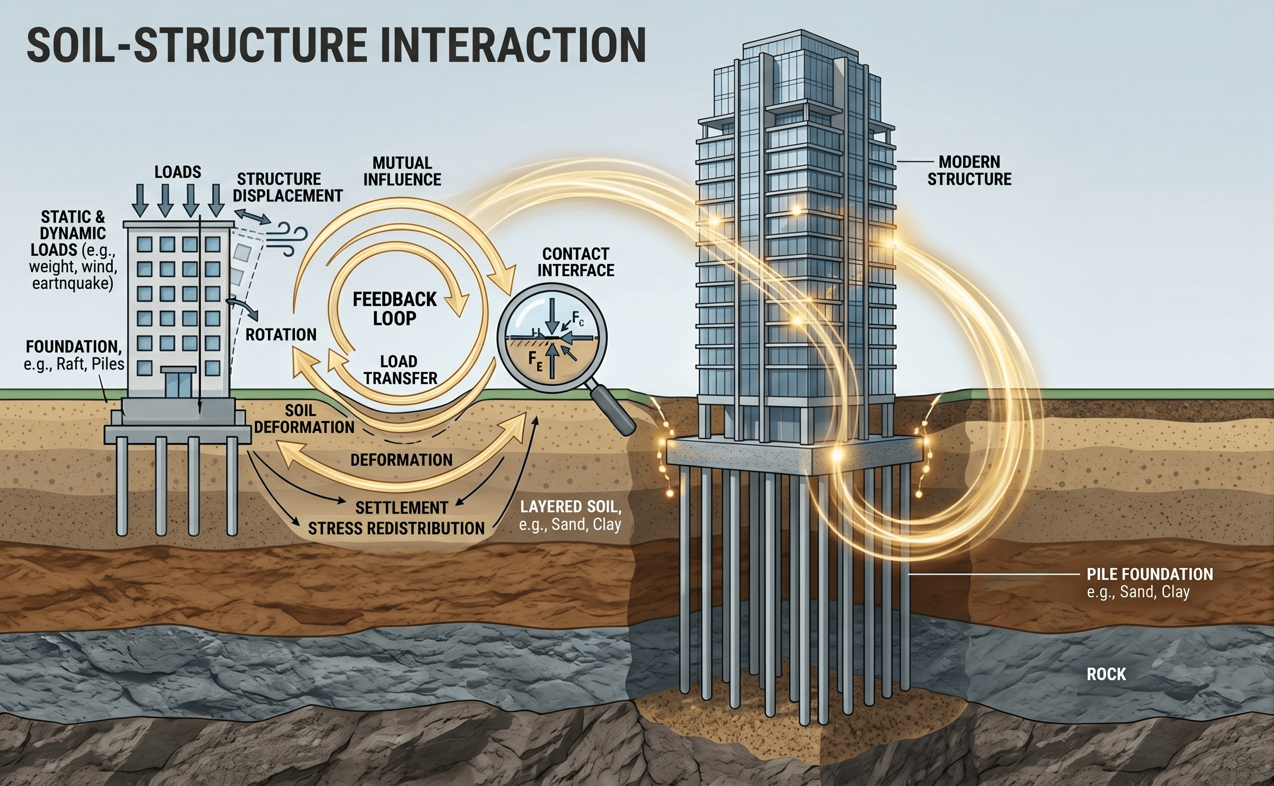
Notice the direction of the feedback loop. The structure is not just pushing downward into the soil; the soil’s stiffness, layering, drainage state, and nonlinear behavior also change how the structure rotates, settles, vibrates, and redistributes load.
What is soil-structure interaction?
Soil-structure interaction, often shortened to SSI, is the engineering concept that the structure, the foundation, and the supporting ground respond together rather than independently. In a textbook fixed-base model, the base of a building, bridge pier, wall, or tank is assumed not to move. In the field, that assumption is often too simple. Soil compresses, shears, drains, creeps, and sometimes cracks or yields. Foundations spread load over area, mobilize contact pressure unevenly, and may rock, slide, or rotate. The structure then responds to those support movements.
This matters because the real design question is rarely “Can the structural frame carry the load?” by itself. The better question is “How does the entire ground-foundation-structure system carry the load, and what movements come with it?” That shift in thinking is what separates a quick rigid-base check from a defensible SSI assessment.
In geotechnical engineering, SSI connects directly to Soil Mechanics, Foundation Design, Settlement Analysis, and Geotechnical Software. It is one of the key bridges between geotechnical and structural analysis because it affects both demand and capacity.
Core principles, variables, and units
SSI depends on stiffness compatibility, load transfer, movement compatibility, and energy dissipation. A very stiff structure on soft soil behaves differently from a flexible structure on dense ground. The same foundation geometry may act nearly fixed in one soil profile and noticeably flexible in another. That is why engineers focus first on relative stiffness, not just absolute values.
Key variables and typical ranges
The important variables are usually soil modulus, shear wave velocity, damping, foundation size, embedment, structural stiffness, load level, and groundwater or drainage conditions. Exact values depend on the project, but what matters most is whether the chosen range is realistic for the strain level and problem type. A modulus taken from a low-strain test may be far too stiff for settlement or seismic deformation analysis unless it is reduced appropriately.
- \(E_s\) Soil Young’s modulus; often reported in kPa, MPa, or ksi. Highly strain-dependent and usually more uncertain than structural stiffness.
- \(G\) Shear modulus of soil; important for springs, vibration, and seismic SSI. Often linked to \(V_s\) through density.
- \(V_s\) Shear wave velocity, usually in m/s or ft/s; commonly used to estimate small-strain stiffness and site class effects.
- \(k\) Idealized foundation spring stiffness in translation or rotation, such as kN/m, kip/in, or kN·m/rad.
- \(c\) Equivalent dashpot or damping coefficient used in dynamic idealizations of foundation response.
- \(B, L\) Foundation plan dimensions. Larger foundations often experience stronger kinematic averaging and different stiffness behavior than small footings.
- \(q\) Contact pressure or bearing stress. Distribution may be nonuniform when moments, eccentricity, or rocking are present.
- \(s, \theta\) Settlement and rotation; often the most decision-driving outputs for serviceability and cracking checks.
Always ask what strain level the soil parameter came from. Small-strain stiffness is useful, but using it directly in a movement-sensitive model can underpredict settlement and overstate foundation restraint.
Decision logic or design workflow
Most projects do not start with a full finite element SSI model. Good practice is to begin with the engineering question, then choose the simplest model that can answer it. If the project is governed by ultimate strength alone and the base is clearly stiff relative to the structure, a fixed-base approximation may be acceptable. If serviceability, settlement, rocking, adjacent structures, machine vibration, or seismic performance matter, a more explicit SSI treatment is usually warranted.
1) Define the performance concern: strength, movement, vibration, or seismic demand.
2) Build a subsurface model using investigation, groundwater, and realistic soil parameters.
3) Compare likely foundation flexibility to structural stiffness.
4) Start with hand checks or springs if behavior is simple and nearly linear.
5) Escalate to coupled numerical modeling when geometry, staging, nonlinearity, layering, or risk make simplified assumptions unreliable.
6) Check both force effects and movement compatibility before finalizing design.
This workflow prevents two common problems: over-modeling a simple case and under-modeling a sensitive one. The goal is not to use the most advanced tool by default. The goal is to use a model that is proportional to the uncertainty and consequences of the project.
Equations and calculations
SSI can be handled with anything from closed-form springs to full nonlinear time-history analysis. For introductory design work, engineers often start by idealizing the ground beneath a foundation as translational and rotational springs.
This is the basic spring idea: foundation stiffness \(k\) equals applied load \(P\) divided by movement \(\delta\). In real SSI work, the relationship is often nonlinear, direction-dependent, and coupled, but this equation captures the core idea that support flexibility can be represented by an equivalent resistance to motion.
For dynamic SSI, the small-strain shear modulus \(G_{\max}\) is often estimated from mass density \(\rho\) and shear wave velocity \(V_s\). That value is then reduced as appropriate for the expected strain level. This is one reason seismic testing and site characterization are so useful when SSI affects period shift, damping, or foundation impedance.
This form represents a common elastic settlement concept, where settlement \(s\) depends on contact stress \(q\), footing width \(B\), soil modulus \(E_s\), Poisson’s ratio \(\nu\), and an influence factor \(I_s\). It is not universal, but it helps explain why stiffness, footing size, and stress level drive support movement. Once that movement exists, the structure no longer behaves as though it is fixed at grade.
Worked example
Example: shallow foundation supporting a stiff frame on medium clay
Consider a square footing supporting one column line of a low-rise frame. The footing carries a service load of 1,200 kN and bears on medium clay with a representative service-level modulus of 20 MPa. A rigid-base structural model predicts modest frame drift and uniform force distribution, but the geotechnical review suggests total settlement near 20 mm with some rotation under combined axial load and moment.
At first glance, 20 mm may not sound severe. The key SSI question is not only “Is 20 mm acceptable?” but also “What does 20 mm do to the frame and superstructure finishes?” If support rotation changes column end moments, redistributes beam forces, or increases facade cracking risk, then the fixed-base structural results may no longer represent the true behavior well enough for design decisions.
A practical next step is to replace the fixed supports with vertical and rotational springs calibrated from hand calculations, plate-load correlations, or a more formal geotechnical model. The structural engineer can then compare frame forces, drifts, and support reactions between the rigid-base and flexible-base cases. If the results are similar, the simplified assumption was justified. If the flexible-base case changes demand meaningfully, SSI has become a design driver rather than a background detail.
This is a realistic SSI workflow because it does not jump immediately to a full 3D nonlinear model. It starts by testing whether support flexibility actually matters for the project decisions on the table.
Engineering judgment and field reality
SSI is one of those topics where field reality can quickly outrun clean theoretical assumptions. Soil properties vary with depth, moisture, stress history, strain level, and construction disturbance. Excavation changes confinement. Dewatering changes effective stress. Fill placement changes density and drainage. A foundation cast on a wet subgrade may not behave like the idealized support assumed in analysis.
Experienced engineers therefore focus on what actually controls the system: compressible layers, groundwater fluctuation, contact conditions, embedment, staged loading, and whether the structure can tolerate the predicted movement pattern. In many building projects, serviceability controls before strength does. A foundation may have adequate bearing capacity yet still cause problems because differential settlement or rotation damages partitions, cladding, piping, or equipment alignment.
Field instrumentation can also be a major SSI tool. Settlement points, inclinometers, piezometers, strain gauges, and vibration monitoring help confirm whether the assumed stiffness and boundary behavior were realistic. For high-consequence excavations, retaining systems, tunnels, or machine foundations, this feedback is often more valuable than a visually impressive but weakly calibrated numerical model.
The biggest SSI mistake in practice is often not a math error but an input error: using convenient soil properties that do not match the actual construction sequence, drainage state, or strain level.
When this breaks down
Simplified SSI methods break down when the behavior becomes strongly nonlinear, path-dependent, or three-dimensional. Examples include gapping and uplift beneath mat or shallow foundations, cyclic degradation in loose saturated soils, liquefaction, highly layered ground, deeply embedded basements, strong soil-structure resonance, and staged excavation support problems where stiffness evolves during construction.
The method also breaks down when the model resolution is finer than the input quality. A dense finite element mesh does not make weak parameters more reliable. If the project has only broad index data and limited site characterization, a sophisticated coupled model may produce precise-looking answers with poor real-world credibility.
Another limit appears when engineers treat SSI as automatically beneficial in seismic design. Period lengthening and damping can reduce some force measures, but they may also increase displacement, P-Delta sensitivity, rocking demand, downdrag effects, or permanent movement. That is why dynamic SSI should be judged by the full performance objective, not just one reduced base shear value.
Common pitfalls and engineering checks
- Using a fixed-base structural model when settlement or rocking is clearly plausible.
- Using small-strain geophysical stiffness directly for service-level deformation checks without reduction.
- Assuming uniform contact pressure when significant eccentricity or nonlinear contact is expected.
- Checking strength but not movement compatibility with slabs, utilities, facade systems, or adjacent structures.
- Ignoring the effect of groundwater, construction sequence, or excavation-induced unloading on support stiffness.
- Using software output without independent hand checks on stiffness, reaction levels, and movement order of magnitude.
Treating the soil as a single constant spring for every load case can hide the most important part of SSI: support conditions often change with load level, direction, drainage condition, and strain amplitude.
Before trusting an SSI model, ask three questions: Are the support movements realistic? Do the reaction patterns make physical sense? Would the answer still be defensible if the key soil stiffness values were 30 to 50 percent lower?
| Parameter | Symbol | Typical units | Why it matters |
|---|---|---|---|
| Soil modulus | \(E_s\) | kPa, MPa, ksi | Controls settlement and spring idealization for many service-level problems. |
| Shear modulus | \(G\) | kPa, MPa, ksi | Important for vibration, seismic response, and foundation impedance. |
| Shear wave velocity | \(V_s\) | m/s, ft/s | Links field seismic testing to low-strain stiffness and dynamic site behavior. |
| Settlement | \(s\) | mm, in | Often a stronger design limiter than bearing capacity alone. |
| Foundation rotation | \(\theta\) | rad, mrad | Can redistribute moments and cause serviceability problems even when total settlement is modest. |
| Damping | \(\zeta\) or \(c\) | ratio or force-time/length | Affects dynamic response, machine foundations, and seismic SSI. |
Visualizing soil-structure interaction
A useful way to picture SSI is to compare three support assumptions for the same structure: fixed base, elastic springs, and nonlinear contact. In the fixed-base case, the base does not translate or rotate. In the spring case, the foundation can move but still behaves proportionally. In the nonlinear contact case, compression may localize, edges may lift, stiffness changes with load, and permanent movement may accumulate.
That mental picture helps explain why SSI is not a single formula. It is a modeling framework for representing how support conditions evolve as the soil and the foundation respond to loading.
The main infographic already covers the core feedback loop, so this section stays text-only to avoid redundant visuals.
Relevant standards and design references
SSI rarely comes from one standalone code clause. It is usually governed by a combination of geotechnical investigation standards, foundation design provisions, seismic criteria, and project-specific performance requirements.
- ASCE 7: Used when seismic response, site class, period effects, and structural demand matter. SSI implications often appear in how base flexibility changes demand and drift behavior.
- IBC and local building code adoption: Establish the governing structural and geotechnical code framework for the jurisdiction and often determine how site class and seismic design parameters are applied.
- AASHTO LRFD Bridge Design Specifications: Important for bridge foundations, abutments, piers, and earth-structure interaction where movement, stiffness, and seismic effects are part of the design basis.
- FHWA geotechnical and earth-retaining references: Useful for excavations, walls, bridge foundations, and soil-structure systems where construction staging and deformation control are central.
- Project geotechnical report and laboratory/in-situ testing standards: The most influential SSI input often comes from the site-specific subsurface model, not from a generic handbook value.
Frequently asked questions
Foundation design is the process of selecting and sizing the system that transfers load into the ground. Soil-structure interaction looks at the coupled behavior of the structure, foundation, and soil together, especially when support flexibility, damping, rocking, or settlement change the structural response.
SSI becomes especially important when the supporting ground is soft, layered, saturated, or nonlinear; when the foundation is large, embedded, or heavily loaded; or when seismic, vibration, and serviceability issues control the project more than simple ultimate strength checks.
Sometimes, but not always in a helpful way. SSI may lengthen the effective period and increase damping, which can reduce some force measures, yet it can also increase displacement, rocking demand, local damage potential, or permanent ground-related movement.
A spring model is often a strong first step and may be sufficient for many practical problems, especially when the behavior is near-linear and the main concern is support flexibility. It becomes less reliable when contact nonlinearity, staged construction, strong layering, uplift, liquefaction, or complex dynamic effects dominate.
SSI shows up in shallow foundations, deep foundations, rafts, retaining walls, basement systems, tunnels, tanks, machine foundations, bridge supports, and seismic design of structures where support movement or soil flexibility materially affects performance.
Summary and next steps
Soil-structure interaction is the idea that the ground, foundation, and structure form one coupled system. Once you accept that the support is not perfectly rigid, the design conversation improves immediately: you begin checking not only strength, but also settlement, rotation, damping, stiffness compatibility, and the consequences of movement on the structure above.
In practical engineering, the best SSI approach is usually staged. Start with the performance question, build a realistic subsurface model, and use the simplest defensible analysis that answers the project need. Escalate only when geometry, risk, seismic behavior, or nonlinearity require it.
The most useful habit is to stay skeptical of “clean” model results that do not reflect field conditions. Good SSI work is not just better math. It is better judgment about what the soil is likely to do, how the structure will react, and what level of modeling is justified by the project.
Where to go next
Continue your learning path with these curated next steps.
-
Read a deeper dive on Soil Mechanics
Build the ground behavior fundamentals behind stiffness, stress transfer, drainage, and deformation.
-
Study Foundation Design
Extend SSI thinking into footing, raft, and system selection decisions.
-
Explore Geotechnical Software
See how SSI concepts are implemented in practical analysis workflows and numerical models.