Key Takeaways
- Core idea: Glass fiber reinforced concrete is a cement-based composite that uses alkali-resistant glass fibers to improve crack control and thin-section performance.
- Engineering use: GFRC is most common in lightweight architectural panels, façade cladding, trim, column covers, soffits, molded profiles, and decorative precast elements.
- What controls it: Fiber type, fiber distribution, cement matrix quality, curing, panel thickness, anchors, joints, and support framing control real performance.
- Practical check: GFRC should not automatically be treated as a substitute for reinforced concrete beams, slabs, columns, walls, or foundations.
Table of Contents
Introduction
Glass fiber reinforced concrete, or GFRC, is a cement-based composite reinforced with alkali-resistant glass fibers. The fibers help control cracking, improve tensile behavior in thin sections, and allow lightweight architectural panels, cladding, trim, and molded concrete elements that would often be too heavy or brittle if made from ordinary precast concrete.
Glass Fiber Reinforced Concrete Composition
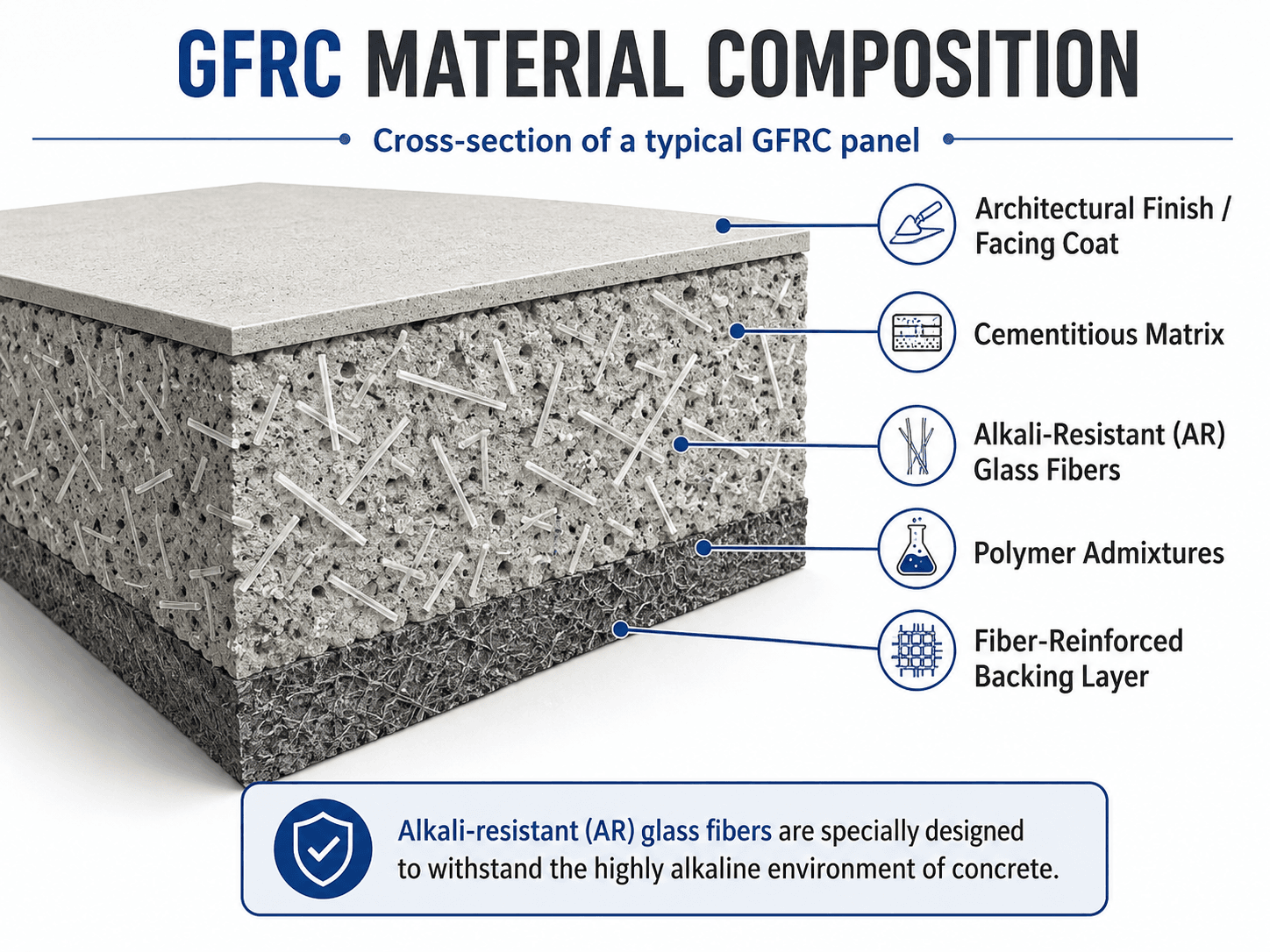
Notice that the glass fibers are distributed through the cementitious backing rather than placed like traditional reinforcing bars. That difference is why GFRC behaves well in thin panels and architectural shapes, but it also means connection design and panel support must be reviewed carefully.
What Is Glass Fiber Reinforced Concrete?
Glass fiber reinforced concrete is a composite material made from cement, fine aggregate, water, admixtures, and alkali-resistant glass fibers. The cementitious matrix provides the body of the material, while the glass fibers help bridge small cracks, distribute tensile stress, and improve performance in thin sections.
In structural engineering, the most important distinction is that GFRC is usually a specialized concrete product rather than ordinary structural concrete with a small amount of fiber added. It is commonly used for façade panels, decorative precast units, cornices, soffits, column covers, wall panels, and complex architectural forms where low weight and shape flexibility are valuable.
GFRC is also different from concrete reinforced with fiberglass rebar. In GFRC, chopped alkali-resistant glass fibers are typically dispersed through the matrix or sprayed into a backing layer. The fibers improve distributed crack control, while conventional rebar provides continuous reinforcement for larger structural members.
GFRC is a material system. The fibers matter, but so do the matrix, curing, panel thickness, anchorage, joints, support frame, and fabrication quality.
How GFRC Works
Ordinary concrete is strong in compression but weak in tension. GFRC improves the behavior of thin concrete sections by adding many small alkali-resistant glass fibers throughout the cementitious matrix. When microcracks begin to form, the fibers help bridge the cracks and distribute stress over a wider area instead of allowing one crack to dominate immediately.
Crack bridging and tensile behavior
The fibers do not make the material behave like a reinforced concrete beam with continuous steel bars. Instead, they improve local tensile resistance, impact toughness, and crack distribution. This is especially useful in thin architectural panels where conventional rebar would be difficult to place and where small cracks can quickly affect appearance and serviceability.
Why alkali-resistant glass matters
Fresh and hardened cement paste is highly alkaline. Ordinary glass fibers can lose performance in that environment, so GFRC uses alkali-resistant glass fibers designed for cement-based materials. This is one reason GFRC should be specified as a controlled material system, not treated as a generic concrete mix with random chopped glass.
Why thin sections are possible
GFRC can often be made much thinner than conventional precast concrete because distributed fibers support crack control and handling resistance in the cementitious shell. The result is a panel that may be lighter, easier to transport, easier to lift, and better suited to detailed architectural profiles.
GFRC vs Traditional Concrete
Searchers often ask whether GFRC is stronger than concrete, but the better comparison is performance by use case. Traditional concrete is the standard choice for slabs, beams, columns, walls, foundations, and many cast-in-place structures. GFRC is usually selected when thin shape, weight reduction, surface detail, crack control, and corrosion-resistant fiber reinforcement are more important than primary structural load carrying.
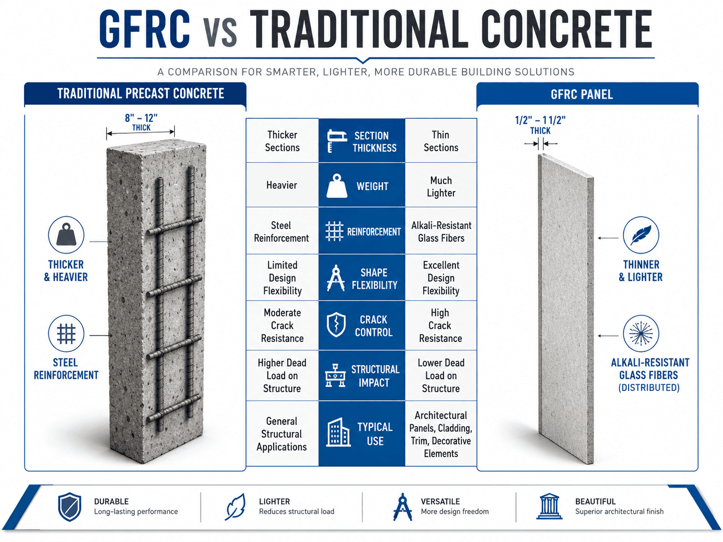
| Comparison point | GFRC | Traditional concrete |
|---|---|---|
| Typical reinforcement | Distributed alkali-resistant glass fibers | Steel rebar, welded wire reinforcement, prestressing steel, or no reinforcement depending on application |
| Common use | Architectural panels, cladding, trim, molded elements, column covers, soffits, and decorative precast work | Slabs, beams, columns, foundations, walls, pavements, and general cast-in-place or precast construction |
| Weight | Often much lighter because it can be made in thin sections | Usually heavier for similar surface coverage |
| Shape flexibility | Excellent for curves, profiles, textures, and complex architectural details | Good for many forms, but heavier sections and reinforcement placement may limit fine detail |
| Corrosion behavior | Glass fibers do not corrode like steel, but anchors and frames still require corrosion-resistant detailing | Steel reinforcement can corrode if moisture, chlorides, carbonation, or poor cover conditions are present |
| Structural role | Usually supported by frames, anchors, brackets, or backup structure | Often part of the primary gravity or lateral load-resisting system |
Where GFRC Is Used in Structural and Architectural Work
GFRC is most valuable where appearance, weight, repetition, and geometry drive the design. It is common on buildings that need a concrete, stone, or sculptural appearance without the dead load of thick precast concrete. In many projects, the GFRC panel is part of the enclosure or architectural system while the building frame carries the main structural loads.
- Architectural cladding: thin panels can create a concrete or stone-like appearance with reduced dead load.
- Cornices, trim, and ornamentation: molded profiles can replicate complex shapes without massive cast stone sections.
- Column covers and fascia units: GFRC can hide structural framing while maintaining a durable architectural finish.
- Soffits and overhangs: low weight helps reduce support demand and installation difficulty.
- Restoration and replacement elements: GFRC can reproduce historic profiles where weight, cost, or fabrication constraints make natural stone difficult.
- Countertops and specialty elements: premix GFRC is often used for thin, custom concrete surfaces and furniture-like components.
Before selecting GFRC, ask whether the project needs a lightweight architectural shell or a primary structural member. GFRC excels at the first problem; conventional reinforced concrete is usually better suited to the second.
What Controls GFRC Performance?
GFRC performance is controlled by more than fiber content. The matrix must bond to the fibers, the fibers must survive the cement environment, the panel must be thick enough for handling and service loads, and the connections must transfer loads without overstressing the thin shell.
| Factor | Why it matters | Engineering implication |
|---|---|---|
| Alkali-resistant glass fiber | The cement matrix is alkaline, so the fiber type affects long-term durability. | Specify appropriate AR glass fibers rather than assuming any chopped glass fiber is acceptable. |
| Fiber distribution | Clumps, low fiber content, poor orientation, or uneven spray coverage can create weak zones. | Production method, mixing time, spray technique, and quality control directly affect performance. |
| Matrix quality | Cement, sand grading, water control, polymer modifiers, admixtures, and curing affect strength and durability. | A good fiber system cannot rescue a weak, porous, poorly cured, or inconsistent matrix. |
| Panel thickness | Thin sections reduce weight but increase sensitivity to handling, edge damage, and connection stresses. | Thickness must be selected for fabrication, shipping, erection, wind load, deflection, and serviceability. |
| Anchors and brackets | Loads must move from the GFRC panel into a frame or backup structure. | Connection layout often controls practical panel behavior more than the nominal material strength. |
| Joints and movement | Panels experience thermal movement, moisture movement, building drift, and support tolerances. | Joint sizing, sealant design, drainage, and tolerance coordination are essential for façade performance. |
GFRC Cladding Panels and Connection Systems
On building envelopes, GFRC should be understood as a panel system rather than a standalone sheet of concrete. The visible panel, metal frame, anchors, brackets, connection hardware, backup wall, insulation, air cavity, sealant, and joints all affect how the system performs under wind, gravity, thermal movement, water exposure, and installation tolerances.
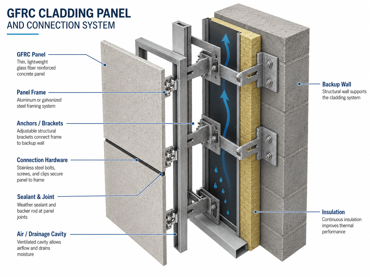
Load path through a GFRC panel system
Wind pressure and suction act on the panel face, then move through the GFRC shell into flex anchors, frames, brackets, and the backup structure. Gravity loads from the panel self-weight must also be supported without creating local cracking, rotation, or unintended restraint.
Moisture and movement control
GFRC panels are not just judged by strength. Water management, sealant continuity, drainage paths, thermal movement, building drift, and installation tolerance all matter. A panel that is strong enough in isolation can still perform poorly if joints leak, anchors restrain movement, or brackets concentrate stress.
Why connection detailing can control the design
The thin GFRC skin can be more sensitive to local stress concentrations than a thick reinforced concrete wall. Engineers should review anchor spacing, eccentricity, frame stiffness, welds, bolts, embedded plates, and movement allowance so load transfer is predictable and not concentrated into brittle edges or returns.
Spray-Up GFRC vs Premix GFRC
GFRC is commonly produced by either spray-up or premix methods. The right method depends on the size of the element, production equipment, required finish, fiber content, shape complexity, and quality control expectations.
| Method | How it works | Typical use | Practical concern |
|---|---|---|---|
| Spray-up GFRC | Cementitious slurry and chopped glass fibers are sprayed into a mold, often with a controlled backing layer. | Architectural panels, larger façade elements, complex molds, and production environments with trained crews. | Requires consistent spray technique, compaction, thickness control, and curing. |
| Premix GFRC | Chopped AR glass fibers are mixed into the cementitious material before placement. | Countertops, smaller panels, furniture-like elements, and specialty precast items. | Fiber balling, workability loss, and poor distribution can reduce performance. |
| Face coat with backing layer | A decorative face mix is placed first, followed by a fiber-reinforced backing layer. | Architectural elements where surface appearance and structural backing both matter. | Bond between layers, curing compatibility, and shrinkage behavior must be controlled. |
GFRC Design Review Checklist
Use this checklist as a practical review aid when evaluating whether GFRC is appropriate for a panel, cladding element, decorative precast component, or lightweight architectural feature. It does not replace project specifications or engineering calculations, but it helps identify the issues that usually control performance.
Start with the function of the element, confirm whether it is architectural or primary structural, define the exposure and loads, choose the production method, review panel thickness and fiber system, then check anchors, joints, tolerances, handling, and quality control before final approval.
| Check or decision | What to look for | Why it matters |
|---|---|---|
| Structural role | Cladding, trim, cover, panel, countertop, or actual load-resisting element. | GFRC is usually appropriate for thin architectural elements, not as a direct replacement for primary reinforced concrete members. |
| Fiber system | Alkali-resistant glass fiber type, dosage, length, distribution, and production method. | The wrong fiber or poor distribution can undermine crack control and durability. |
| Panel thickness | Minimum thickness, returns, ribs, edge details, and local thickened regions near anchors. | Thin panels save weight but may become sensitive to handling, edge damage, and connection stresses. |
| Connection design | Anchors, flex anchors, brackets, embedded hardware, frame stiffness, and backup support. | Connections transfer wind and gravity loads; poor detailing can crack the panel or overstress the backup structure. |
| Movement joints | Thermal movement, shrinkage, building drift, sealant width, backer rod, and drainage path. | Restrained movement can cause cracks, sealant failure, leakage, or panel distress. |
| Handling and erection | Lifting points, temporary bracing, shipping orientation, edge protection, and storage support. | Thin panels may be damaged before service if temporary construction loads are ignored. |
| Quality control | Mockups, shop drawings, curing plan, production records, finish samples, and handling procedures. | GFRC performance depends heavily on fabrication consistency and installation discipline. |
When to Choose GFRC
GFRC is usually the right material when the project needs a durable concrete appearance with lower weight, thinner sections, and more architectural freedom. It is less appropriate when the main problem is heavy structural load carrying, high ductility demand, or conventional reinforced concrete behavior.
| Project condition | GFRC is a strong fit when… | Be cautious when… |
|---|---|---|
| Architectural façade | The design needs lightweight panels, molded detail, or a stone-like concrete appearance. | The support frame, anchors, drift, and joints have not been coordinated. |
| Decorative trim or cornice | The element would be too heavy or difficult to install as thick cast stone or precast concrete. | Thin edges, returns, or lifting points are likely to be damaged during handling. |
| Primary structural member | A qualified engineer has specifically designed and justified the system for the load path. | GFRC is being chosen simply because it is assumed to be “stronger concrete.” |
| Exterior exposure | Fiber type, matrix, curing, joints, sealants, drainage, and metal hardware are specified correctly. | Moisture control, freeze-thaw exposure, corrosion of hardware, or sealant maintenance is ignored. |
Engineering Judgment and Field Reality
GFRC often looks simple because the finished panel can be thin and clean, but the real engineering problem is usually behind the surface. The support frame, bracket layout, tolerance stack-up, lifting points, sealant joints, and backup wall condition determine whether the panel behaves as intended after fabrication and installation.
Field problems often occur when GFRC is judged like a decorative finish instead of a façade component. A panel may satisfy appearance requirements while still having inadequate support, poorly coordinated anchors, insufficient movement capacity, or weak quality control during curing and handling.
The panel face is what people see, but the connection system is what keeps the installation reliable. For exterior GFRC, review the hidden hardware and movement joints as carefully as the finish.
When This Breaks Down
GFRC becomes risky when it is used outside the assumptions that make it useful. Thin, lightweight, fiber-reinforced panels are efficient when loads, supports, movement, exposure, and fabrication are controlled. They are not automatically suitable for every concrete application.
- Primary structural substitution: using GFRC as if it were a reinforced concrete beam, slab, column, wall, or foundation can create unsafe assumptions about load path and ductility.
- Poor fiber control: uneven fiber distribution, fiber clumps, low dosage, or the wrong fiber type can reduce crack control and durability.
- Connection restraint: anchors that prevent expected movement can cause cracking, bowing, or local distress near connection points.
- Weak curing and production control: inconsistent batching, curing, compaction, or layer bonding can create panels that do not match design assumptions.
- Ignoring handling loads: panels can be damaged during stripping, lifting, shipping, storage, or installation even if they are adequate in final service.
- Assuming the panel is the whole system: exterior GFRC performance also depends on sealants, drainage, insulation, frame corrosion resistance, and backup wall coordination.
Common Mistakes and Practical Checks
The most common GFRC mistakes come from treating the material as either ordinary concrete or a purely decorative product. It is neither. Good GFRC design requires material control, connection logic, and realistic construction review.
- Calling all glass fiber concrete GFRC: true GFRC should use appropriate alkali-resistant glass fibers and controlled production.
- Assuming lighter means weaker: GFRC can perform well in thin panels, but the relevant question is whether it satisfies the specific load, connection, and serviceability requirements.
- Assuming fibers replace all reinforcement: distributed fibers help crack control, but they do not automatically replace continuous reinforcement or engineered anchors where those are required.
- Ignoring joints: sealant, backer rod, movement gaps, and drainage details can control long-term façade performance.
- Reviewing only the panel face: finish quality is important, but anchors, frames, embedded hardware, and backup support are just as important.
Do not specify GFRC only because it is “stronger concrete.” Specify it because its thin-section, lightweight, crack-control, and architectural forming advantages solve a real project problem.
Standards and Design Reference Context
GFRC specifications should clearly define the fiber system, production method, panel requirements, curing expectations, connection design responsibility, and quality control process. The most directly relevant material reference is the standard for alkali-resistant glass fibers used in GFRC and related cementitious products.
- ASTM International: ASTM C1666/C1666M alkali-resistant glass fiber specification covers minimum requirements for AR glass fibers intended for use in glass fiber reinforced concrete by spray-up, GFRC premix, fiber-reinforced concrete, and other cementitious products.
- Project-specific criteria: Final requirements may also depend on the project specifications, façade engineer, architect, owner standards, panel fabricator, connection designer, local code requirements, and performance testing plan.
- Engineering use: Engineers use material standards and project specifications to confirm that the fibers, matrix, fabrication method, anchorage, tolerances, and testing requirements match the intended GFRC application.
Frequently Asked Questions
Glass fiber reinforced concrete, often called GFRC, is a cement-based composite reinforced with alkali-resistant glass fibers. The fibers help control cracking, improve thin-section behavior, and allow lightweight architectural shapes that would be difficult or inefficient with ordinary concrete.
GFRC is not automatically stronger than regular concrete in every way. Its advantage is usually better thin-section performance, crack control, impact resistance, and strength-to-weight behavior. Conventional reinforced concrete is still typically better for primary beams, slabs, columns, foundations, and heavily loaded structural members.
GFRC can be engineered to resist loads within a panel or component, but it is usually not used as the primary structural system for beams, columns, slabs, or foundations. In buildings, GFRC most often acts as architectural cladding, trim, panels, column covers, or lightweight precast elements supported by a separate frame or backup structure.
Concrete is highly alkaline, so ordinary glass fibers may lose performance over time in the cement matrix. GFRC uses alkali-resistant glass fibers so the reinforcement can better survive the chemical environment while helping distribute tensile stresses and limit cracking.
The main disadvantages of GFRC are higher fabrication sensitivity, the need for experienced production, connection detailing requirements, possible handling damage in thin panels, and limits on primary structural use. It performs best when material quality, curing, panel thickness, anchorage, and movement joints are carefully controlled.
Summary and Next Steps
Glass fiber reinforced concrete is a cementitious composite that uses alkali-resistant glass fibers to improve crack control, toughness, and thin-section performance. Its biggest value is not that it replaces all concrete, but that it allows lightweight, durable, and highly formable architectural components.
The most important checks are fiber type, matrix quality, panel thickness, production method, curing, anchors, support frames, movement joints, and handling loads. GFRC performs best when it is treated as a complete material and panel system rather than a decorative finish or a generic concrete substitute.
Where to go next
Continue your learning path with related Turn2Engineering resources.
-
Composite Materials
Learn how matrix materials, reinforcement, interfaces, stiffness, and durability work together in structural composites.
-
Lightweight Materials
See how engineers compare low-weight systems by strength, stiffness, fire resistance, durability, and connection behavior.
-
High Strength Concrete
Compare GFRC with performance-based concrete materials where compressive strength, durability, and quality control govern design.