Key Takeaways
- Definition: Structural analysis predicts how loads move through a structure and what reactions, forces, moments, and deflections they create.
- Use case: It is used before member design to understand demand, serviceability, stability, and load path behavior.
- Main decision: The most important judgment is whether the analysis model represents the real structure closely enough for the design question.
- Outcome: After reading, you should understand the analysis workflow, key checks, common mistakes, and when deeper modeling is needed.
Table of Contents
Introduction
In brief: Structural analysis models how a structure responds to loads so engineers can calculate forces, reactions, deflections, and stability demands.
Who it’s for: Students and early-career designers.
For informational purposes only. See Terms and Conditions.
A good analysis is not just a software output. It is an engineering model that connects real loads, realistic supports, member stiffness, geometry, and field conditions.
Structural Analysis infographic
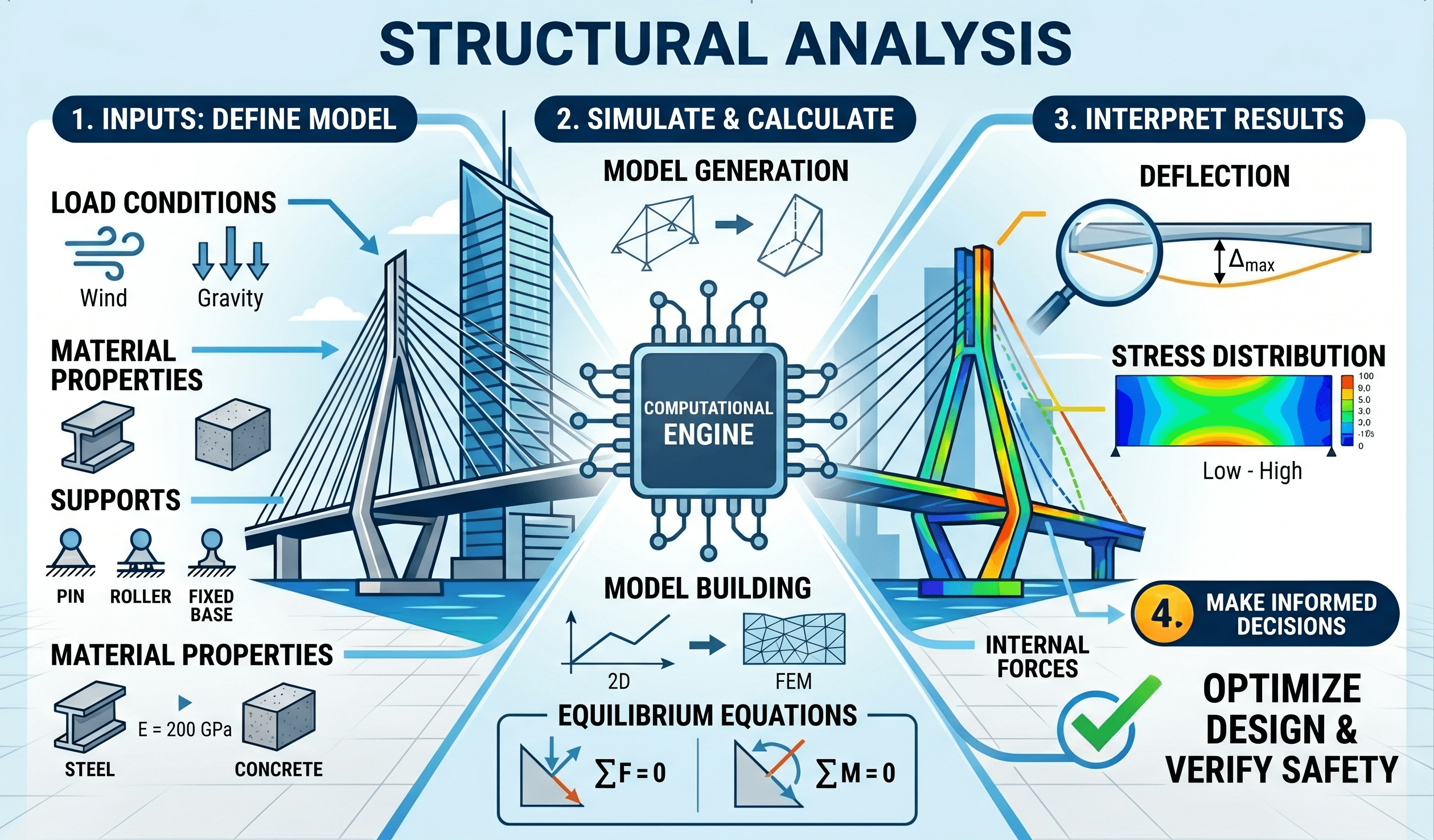
Notice first that the model is only a simplified representation of the real structure. The most important analysis question is whether that simplification still captures the load path, stiffness, and restraint conditions that control behavior.
What is structural analysis?
Structural analysis is the process of determining how a structure responds to loads. It predicts support reactions, internal member forces, bending moments, shear forces, axial forces, torsion, deflections, drift, vibration, and stability effects. Those results become the demand side of structural design.
In practical terms, structural analysis answers a simple question: what does the structure need to resist? A beam analysis may show the maximum bending moment and deflection. A frame analysis may show column axial loads, beam end moments, lateral drift, and second-order effects. A diaphragm analysis may show how wind or seismic forces move into collectors, shear walls, frames, and foundations.
Structural analysis sits between structural loads and material-specific design. Loads define what acts on the structure. Analysis determines how those loads are distributed. Design then checks whether steel, concrete, timber, masonry, connections, and foundations have enough strength, stiffness, ductility, and durability.
The best analysis model is not always the most complex model. It is the simplest model that captures the behavior controlling the decision.
Core principles, variables, and units
Every structural analysis depends on equilibrium, compatibility, material behavior, member stiffness, boundary conditions, and load path continuity. Equilibrium requires forces and moments to balance. Compatibility requires the deformed shape to make physical sense. Stiffness controls how load is shared between members. Supports and releases define what movement is restrained and what movement is allowed.
Key variables and typical units
The variables used in structural analysis vary by system, but the most common outputs are force effects and movement. Engineers usually work in either US customary units such as pounds, kips, inches, and feet, or SI units such as newtons, kilonewtons, millimeters, and meters. The critical rule is to never mix unit systems within one calculation.
- P Axial load, commonly measured in lb, kip, N, or kN.
- V Shear force, used to evaluate webs, stirrups, bearing regions, and connections.
- M Bending moment, used to determine flexural demand in beams, slabs, frames, and walls.
- T Torsion, important when loads are eccentric or members twist under applied demand.
- Δ Deflection or displacement, commonly checked against serviceability limits.
- E Modulus of elasticity, a material stiffness parameter used in deflection and frame analysis.
- I Moment of inertia, a section property that strongly influences bending stiffness.
Equilibrium and compatibility
For simple determinate structures, equilibrium equations may be enough to solve reactions and internal forces. For indeterminate structures, equilibrium alone is not enough because member stiffness and deformation compatibility determine how force is distributed. That is why continuous beams, frames, slabs, and complex lateral systems usually require stiffness-based analysis.
These equilibrium equations are the foundation of analysis. Even when software is used, the final model should still satisfy basic force and moment balance. Reaction totals should match applied loads, and the direction of forces should make physical sense.
Before trusting detailed output, check total applied load against total reactions. This simple check catches many modeling, unit, and load-entry errors.
Structural analysis workflow
A reliable structural analysis follows a deliberate sequence. The goal is not just to produce numbers, but to build confidence that the numbers represent the real behavior of the structure.
Define the structure → identify loads → establish load paths → choose the analysis method → model geometry and supports → assign stiffness and releases → run load combinations → review deflected shape → check reactions and force diagrams → use results for design.
1. Define the structural system
Start by identifying the gravity system, lateral system, support points, diaphragms, collectors, foundations, and major discontinuities. A building with clear vertical load paths behaves differently from one with transfer beams, offsets, cantilevers, podium levels, setbacks, or irregular stiffness.
2. Establish loads and combinations
Loads may include dead load, live load, roof load, snow, wind, seismic, earth pressure, hydrostatic pressure, equipment loads, impact, thermal effects, and construction loads. The analysis should use the correct service or strength load combinations depending on whether the check is for deflection, drift, vibration, stability, or ultimate capacity.
3. Select the analysis method
Hand calculations are useful for simple beams, trusses, and preliminary checks. Two-dimensional frame analysis may be appropriate for regular planar systems. Three-dimensional analysis is often needed when diaphragms, torsion, lateral load distribution, transfer levels, or irregular geometry control the response.
4. Review results before designing members
The first review should not be a code check. It should be an engineering sense check. Look at reactions, force signs, peak moments, shear diagrams, deflected shape, support fixity, member releases, and whether load is flowing through the expected path.
Common methods of structural analysis
Different projects require different levels of analysis. A simple roof beam does not need the same method as an irregular seismic frame or a long-span vibration-sensitive floor. The right method depends on geometry, stiffness, load path complexity, risk, and the question the engineer is trying to answer.
| Method | Best used for | Main limitation | Senior engineer check |
|---|---|---|---|
| Hand calculations | Simple beams, reactions, tributary loads, preliminary sizing | Can miss continuity, load sharing, and three-dimensional behavior | Compare with basic equilibrium and expected diagram shapes |
| Approximate frame analysis | Early lateral system estimates and schematic design | Less accurate for irregular stiffness, offsets, and torsion | Use as a reasonableness check, not a final answer for complex systems |
| Matrix stiffness analysis | Frames, trusses, continuous beams, and many software models | Results depend heavily on releases, supports, and stiffness assumptions | Check deflected shape and member end forces |
| Finite element analysis | Slabs, walls, shells, plates, mats, stress concentrations | Mesh density and boundary assumptions can distort results | Check mesh sensitivity and load distribution |
| Second-order analysis | Slender frames, columns, drift-sensitive systems | Requires realistic stiffness, imperfections, and stability assumptions | Confirm whether P-Delta effects materially increase demand |
| Dynamic analysis | Seismic response, vibration, machinery, pedestrian floors, wind-sensitive structures | Mass, damping, stiffness, and excitation assumptions matter greatly | Check mode shapes, participation, and natural periods |
A strong workflow often combines methods. For example, software may provide final frame forces, while hand calculations verify gravity reactions, tributary load assumptions, and approximate drift. This combination is usually more reliable than relying on one model without independent checks.
Equations and calculations used in structural analysis
Structural analysis can involve many equations, but most practical calculations come back to equilibrium, stiffness, stress, strain, and deformation. The equations below are common starting points for beams and members, especially during preliminary checks.
Stress from axial load
Axial stress equals axial force divided by cross-sectional area. This is a basic check for tension and compression members, but compression members also require stability checks because buckling can control before material strength is reached.
Flexural stress
Flexural stress depends on bending moment, distance from the neutral axis, and moment of inertia. This relationship helps explain why deeper members are much stiffer and stronger in bending than shallow members of the same material.
Elastic beam deflection
Deflection increases dramatically with span length because span appears to the fourth power in many beam deflection expressions. This is why serviceability often controls long-span beams even when strength looks acceptable.
If a beam span doubles, deflection can increase far more than two times. Long spans demand careful stiffness checks, not just strength checks.
Worked example: analyzing a simply supported beam
Example problem
Consider a simply supported steel beam spanning 20 ft with a uniform service load of 1.2 kip/ft. The beam supports floor framing, so the engineer wants an initial estimate of reactions and maximum moment before selecting a trial member.
Step 1: Calculate support reactions
For a simply supported beam with a uniform load, each support takes half the total load.
Step 2: Calculate maximum moment
The maximum bending moment for a simply supported beam under a uniform load occurs at midspan.
Step 3: Interpret the result
The reactions help design bearings, connections, columns, and foundations. The maximum moment helps select a beam with enough flexural capacity. The next checks would include shear, deflection, vibration if applicable, lateral-torsional buckling, and load combinations for final design.
The calculation is simple, but the assumptions are not. If the beam is continuous, partially restrained, composite, laterally unbraced, or supporting concentrated loads, the result changes.
Engineering judgment and field reality
Real structures rarely behave exactly like clean textbook models. Supports may be partially restrained instead of perfectly pinned or fixed. Connections may have rotational stiffness. Slabs may distribute load in two directions. Masonry may crack. Concrete stiffness may change with cracking and creep. Soil support may vary across a foundation. Construction sequencing may create temporary conditions that are more critical than the final condition.
This is where engineering judgment matters. The analyst must decide which effects are important and which simplifications are acceptable. For a simple joist, a conservative single-span beam model may be enough. For a transfer level, podium structure, long cantilever, irregular lateral system, or vibration-sensitive floor, the model needs more care.
Structural drawings show idealized lines and nodes, but the field has tolerances, connection eccentricities, cracked materials, staged construction, and supports that may not behave exactly as assumed.
What experienced engineers watch first
- Whether loads have a continuous path to the foundation.
- Whether model supports match real restraint conditions.
- Whether releases accidentally remove critical moment or torsional resistance.
- Whether stiffness assumptions change force distribution.
- Whether the deflected shape matches expected structural behavior.
- Whether local discontinuities create force concentrations.
For more on force flow through complete systems, study load path analysis. Load path thinking is one of the best ways to catch analysis errors before they become design errors.
When this breaks down
Structural analysis breaks down when the model assumptions no longer match the physical structure. A mathematically precise model can still be wrong if it uses the wrong loads, support restraints, stiffness values, releases, member connectivity, diaphragm assumptions, or boundary conditions.
Common situations that require deeper analysis
- Nonlinear behavior: Large deflections, yielding, cracking, contact, uplift, gap opening, or post-buckling behavior may require nonlinear analysis.
- Second-order effects: Slender frames and compression systems may need P-Delta or stability analysis.
- Dynamic response: Earthquake, wind vibration, machinery, rhythmic activity, and pedestrian-induced vibration may require dynamic methods.
- Irregular geometry: Setbacks, transfer systems, discontinuous walls, eccentric cores, and torsional irregularities can make simple analysis misleading.
- Soil-structure interaction: Foundations, retaining systems, mats, and deep foundations may depend on support flexibility rather than fixed-base assumptions.
- Construction sequencing: Temporary bracing, shoring removal, staged loading, and partially completed systems can control member demand.
Do not use a model just because it runs without errors. A stable software model can still hide missing load paths, accidental releases, or unrealistic boundary conditions.
Common pitfalls and engineering checks
Many structural analysis mistakes are not advanced math mistakes. They are modeling, units, assumptions, and interpretation mistakes. A disciplined review process catches most of them.
- Using service loads for strength design or factored loads for serviceability checks without realizing it.
- Applying loads in the wrong direction or to the wrong members.
- Forgetting self-weight or double-counting dead load.
- Assuming fixed supports where the real connection is flexible.
- Adding member releases that interrupt the intended load path.
- Ignoring diaphragm flexibility or collector forces.
- Trusting peak finite element stresses without checking mesh sensitivity.
- Using cracked or uncracked stiffness inconsistently across a model.
- Not checking deflection, drift, vibration, or stability after strength checks pass.
| Check | What to look for | Why it matters |
|---|---|---|
| Reaction check | Total reactions should match total applied loads | Catches missing loads, unit errors, and support mistakes |
| Deflected shape | Structure should move in the expected direction and pattern | Reveals incorrect fixity, releases, stiffness, or connectivity |
| Force diagram shape | Shear and moment diagrams should match loading patterns | Catches load placement and sign convention mistakes |
| Load path review | Each load should reach a stable support | Prevents discontinuities and unintended force transfer |
| Serviceability review | Check deflection, drift, vibration, and cracking where relevant | Structures can be strong enough but still perform poorly |
| Independent approximation | Use a rough hand check or alternate model | Validates software results before design decisions are made |
Analysis also connects directly to risk. Poor modeling can contribute to distress, excessive movement, cracking, or even structural failure when errors align with weak detailing, unexpected loads, or field changes.
Visualizing structural analysis results
Structural analysis results are easiest to understand when viewed as force flow, not just numbers. Start with the applied loads, then trace reactions, shear, bending moment, axial force, torsion, and deformation through the system.
For beams, the most useful visuals are shear diagrams, moment diagrams, and deflected shape plots. For frames, look at displaced shape, member end moments, lateral drift, base reactions, and axial load patterns. For slabs and walls, contour plots can help, but they require careful interpretation because local peaks may reflect mesh behavior, boundary conditions, or stress concentration rather than design-level demand.
Always view the deformed shape before reviewing detailed output. If the structure does not move the way you expect, the model probably needs correction before the forces are useful.
Relevant standards and design references
Structural analysis itself is based on mechanics, but the loads, combinations, acceptance criteria, and design checks are governed by codes and standards. The exact reference depends on the project location, structure type, material, and authority having jurisdiction.
- International Building Code: Establishes building code requirements, occupancy categories, load criteria references, and minimum design expectations for many building projects.
- ASCE/SEI 7: Provides minimum design loads and load combinations for buildings and other structures, including dead, live, snow, wind, seismic, rain, flood, and ice loads.
- AISC Specification and Steel Manual: Used after analysis to design steel members, connections, stability systems, and strength limit states.
- ACI 318: Used after analysis to design reinforced concrete members, shear walls, slabs, beams, columns, and foundations.
- AASHTO LRFD Bridge Design Specifications: Used for bridge analysis and design, including load models, distribution, service, strength, fatigue, and extreme event limit states.
Standards define minimum requirements, but they do not replace judgment. Engineers still need to choose appropriate models, check assumptions, and coordinate the analysis with real structural behavior and constructability.
Frequently asked questions
Structural analysis is used to predict how a structure responds to loads before the members and connections are designed. It helps engineers determine reactions, shear, moment, axial force, deflection, drift, vibration, and stability demands.
No. Structural analysis calculates the force effects and movements caused by loads, while structural design uses those results to size members, select materials, detail connections, and check code requirements.
Structural analysis becomes unreliable when the model does not represent the real structure, support conditions are wrong, loads are incomplete, material behavior is outside the assumed range, or construction sequencing changes the force path.
Common methods include hand calculations for simple determinate systems, approximate analysis for preliminary design, matrix stiffness methods, finite element analysis, second-order analysis, dynamic analysis, and nonlinear analysis for complex behavior.
Engineers should check load paths, reactions, boundary conditions, member releases, deflected shape, force diagrams, units, load combinations, support assumptions, and whether the results make physical sense before using them for design.
Summary and next steps
Structural analysis is the engineering process used to understand how structures respond to loads. It converts loads and geometry into reactions, internal forces, moments, deflections, drift, vibration response, and stability demands.
The most important part of analysis is not the software or the equation. It is the quality of the model. Loads, supports, stiffness, releases, diaphragms, boundary conditions, and construction realities must represent the real structure closely enough for the design decision.
A strong analysis workflow combines mechanics, code-based loads, practical modeling, independent checks, and field judgment. Before using results for design, always check equilibrium, deflected shape, force diagrams, load paths, and whether the output matches physical intuition.
Where to go next
Continue your learning path with these curated next steps.
-
Study structural loads
Learn how dead, live, wind, seismic, snow, and other loads are defined before they are applied to an analysis model.
-
Review load path analysis
Understand how forces move through slabs, beams, columns, walls, diaphragms, foundations, and soil.
-
Connect analysis to structural inspections
See how field observations help verify whether real structures match design and analysis assumptions.