Key Takeaways
- Definition: Steel design sizes steel members and connections so a structure safely resists loads while meeting serviceability and code requirements.
- Use case: Engineers use steel design for beams, columns, frames, trusses, bracing systems, connections, platforms, and industrial structures.
- Main decision: The controlling limit state may be yielding, buckling, lateral-torsional buckling, deflection, vibration, connection strength, or constructability.
- Outcome: A good steel design is safe, stable, buildable, economical, inspectable, and coordinated with architectural and construction constraints.
Table of Contents
Introduction
In brief: Steel design proportionally selects members and connections so steel structures resist loads, remain stable, and satisfy strength and serviceability limits.
Who it’s for: Students and early-career designers.
For informational purposes only. See Terms and Conditions.
Steel is efficient, predictable, and highly buildable, but it only performs well when load path, stability, bracing, connections, detailing, and field conditions are considered together.
Steel Design infographic
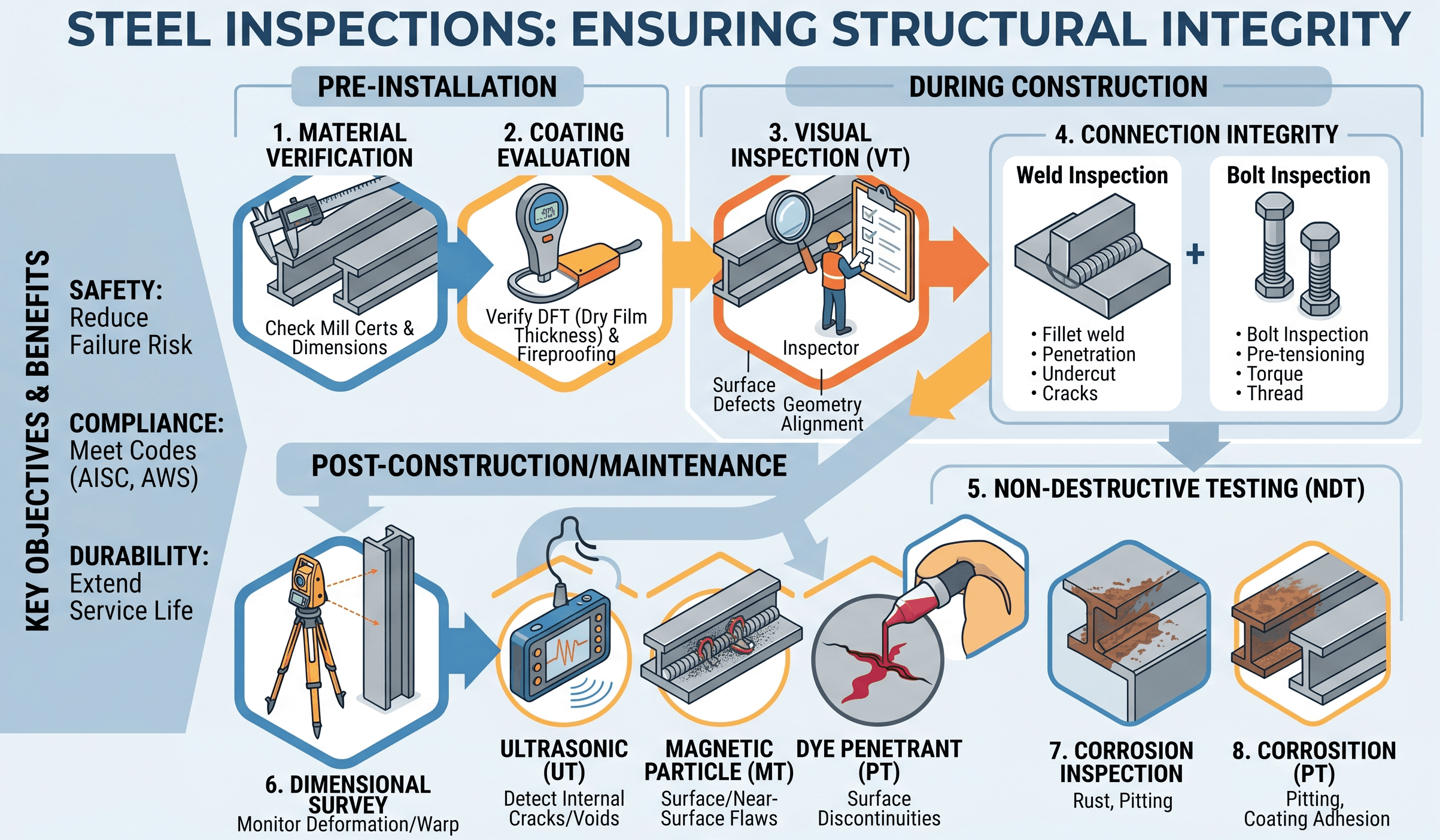
Notice how the important review points are distributed across the structure. A steel beam can be mathematically adequate and still fail the project intent if the connection, brace point, weld, bolt group, camber, or field tolerance is not coordinated.
What is Steel Design?
Steel design is the engineering process used to choose structural steel shapes, connections, and lateral systems that can safely carry the required loads. In building and infrastructure work, it includes beams, columns, trusses, moment frames, braced frames, base plates, anchor rods, diaphragms, platforms, stairs, canopies, and specialty support frames.
The goal is not simply to find a member that is “strong enough.” A complete design checks strength, stability, serviceability, connection behavior, fabrication practicality, erection sequence, corrosion exposure, fire protection, and long-term performance. A steel member that passes a bending check may still be unacceptable if it deflects too much, vibrates noticeably, lacks adequate bracing, or forces an impractical field connection.
Steel design sits inside the broader workflow of structural analysis. Analysis determines load effects such as shear, moment, axial force, drift, and reactions. Steel design turns those effects into member sizes, connection demands, stiffness requirements, and drawings that can be fabricated and built.
Steel design is controlled by limit states. A limit state is a condition where the member, connection, or system no longer satisfies the intended strength, stability, or serviceability requirement.
What controls a steel design?
The controlling requirement changes with the member type and the structure. Short stocky members may be controlled by yielding. Slender compression members may be controlled by buckling. Long unbraced beams may be controlled by lateral-torsional buckling. Floor beams may be governed by deflection or vibration before strength becomes critical.
Common controlling checks
- Flexure: bending capacity of beams, girders, lintels, joists, and frame members.
- Shear: web shear capacity near supports, concentrated loads, openings, and short-span members.
- Axial compression: column strength, effective length, slenderness, and global buckling behavior.
- Axial tension: yielding, rupture, net section checks, block shear, and connection detailing.
- Combined forces: beam-columns, frame members, braces, and members with simultaneous axial force and bending.
- Serviceability: deflection, drift, vibration, ponding, cladding movement, and occupant comfort.
- Connections: bolts, welds, plates, eccentricity, prying action, block shear, and load transfer continuity.
- Stability: frame stability, second-order effects, unbraced lengths, diaphragm assumptions, and lateral bracing.
| Design situation | Likely controlling issue | Senior engineer check |
|---|---|---|
| Long roof beam | Lateral-torsional buckling or deflection | Confirm compression flange bracing is real, continuous, and connected. |
| Interior building column | Axial compression and effective length | Check unbraced length in both axes and verify frame stability assumptions. |
| Moment frame beam | Combined flexure, connection behavior, and drift | Review connection stiffness, panel zones, seismic detailing, and frame drift. |
| Industrial platform | Vibration, local loads, grating support, and field fit-up | Verify concentrated equipment loads and avoid relying only on uniform live load. |
| Canopy or sign support | Wind, torsion, anchor rods, and fatigue | Trace load path into supporting structure and foundation anchorage. |
Steel design workflow
A reliable steel design starts with the load path, not the member table. Before selecting a W-shape, tube, angle, channel, or plate girder, the engineer should understand where the load enters the structure, how it moves through members and connections, and where it finally reaches the foundation.
Define loads → establish load path → analyze forces → choose trial member → check strength → check stability → check serviceability → design connections → review constructability → coordinate details → verify field assumptions.
Step 1: Define loads and combinations
Steel design begins with dead load, live load, roof load, snow, wind, seismic, equipment, crane, thermal, impact, and construction loads where applicable. The governing load combinations depend on the design method and building code basis. A missed load case can make a technically polished calculation meaningless.
Step 2: Select a structural system
The system choice affects every later check. Simple shear connections behave differently from moment connections. Braced frames attract and deliver lateral loads differently from moment frames. Composite beams depend on slab behavior and shear studs. Trusses can be efficient, but connection geometry and erection tolerances often drive the final design.
Step 3: Analyze member demands
Structural analysis produces the factored or service-level forces used for design. For a beam, the key outputs may be moment, shear, reactions, deflection, and required brace spacing. For a column, the key outputs may include axial load, end moments, effective length, drift contribution, and second-order amplification.
Step 4: Check the limit states
After choosing a trial member, the engineer checks the relevant strength and serviceability requirements. These checks should not be isolated. A change that improves strength can increase weight, connection demand, foundation reactions, erection complexity, and cost.
Step 5: Detail the connections
Connections complete the load path. In many projects, connection design is delegated to a specialty engineer, but the main structural engineer still needs to communicate design intent, reactions, connection type assumptions, and stability requirements clearly.
Steel members and where they are used
Structural steel is available in many shapes, and each shape behaves differently. Wide-flange sections are common for beams and columns because they efficiently resist bending about their strong axis. Hollow structural sections are useful where torsion, biaxial bending, exposed appearance, or closed-section efficiency matters. Plates, angles, channels, and tees are often used for connections, bracing, edge framing, and built-up assemblies.
| Steel member type | Typical use | Design consideration |
|---|---|---|
| Wide-flange beam | Floor beams, girders, roof framing | Check flexure, shear, deflection, and compression flange bracing. |
| Wide-flange column | Gravity columns and frame columns | Check axial compression, bending interaction, slenderness, and base plate forces. |
| HSS tube or pipe | Braces, columns, exposed frames, sign supports | Connection detailing and local wall strength often control. |
| Angle or channel | Bracing, lintels, edge members, miscellaneous steel | Eccentric loading and weak-axis behavior can be easy to overlook. |
| Plate girder | Long-span or heavy-load applications | Web slenderness, stiffeners, flange proportions, and fabrication cost matter. |
Member selection should also reflect availability and fabrication. A theoretically efficient shape may not be economical if it is uncommon, difficult to source, hard to connect, or heavier to erect than a slightly larger but more standard member.
Core steel design equations and checks
Steel design uses many equations, but the central comparison is usually demand versus available strength. The demand comes from analysis. The available strength comes from the governing steel specification, adjusted for the applicable limit state.
In LRFD form, the factored required strength \(R_u\) must not exceed the design strength \(\phi R_n\). Here, \(R_n\) is nominal strength and \(\phi\) is the resistance factor associated with the limit state.
In ASD form, the required service-level strength \(R_a\) must not exceed the allowable strength \(R_n / \Omega\). The key is consistency: do not mix LRFD load effects with ASD allowable strengths unless the governing procedure explicitly permits it.
- \(R_u\) Required factored strength for LRFD checks, such as factored moment, shear, axial force, or reaction.
- \(R_a\) Required service-level strength for ASD checks.
- \(R_n\) Nominal strength based on the applicable steel limit state.
- \(\phi\) LRFD resistance factor applied to nominal strength.
- \(\Omega\) ASD safety factor used to convert nominal strength to allowable strength.
Beam flexure concept
For a compact laterally braced steel beam, flexural strength often relates to plastic moment capacity. For an unbraced beam, lateral-torsional buckling may reduce available strength before the full plastic moment can develop.
Column compression concept
Column design depends strongly on slenderness. A short compact column can approach yield-controlled behavior, while a long slender column may buckle at a much lower stress. That is why unbraced length and effective length assumptions are not minor inputs.
Before refining a member size, identify the controlling limit state. Increasing section area may not solve the problem if the real issue is unbraced length, connection eccentricity, drift, or vibration.
Connections, load path, and detailing
Connections are often where steel design becomes real. A beam, column, or brace can have adequate member strength, but the structure still depends on bolts, welds, plates, stiffeners, clips, gussets, and anchor rods to transfer force correctly. Connection details also influence erection safety, inspection access, tolerance, and future maintenance.
Common connection types
- Shear connections: transfer vertical reaction while allowing rotation, commonly used for simple beams.
- Moment connections: transfer moment and rotation restraint, commonly used in moment frames and rigid frames.
- Bracing connections: transfer axial forces from diagonal braces into beams, columns, gusset plates, and foundations.
- Base plates: transfer column loads into concrete foundations through bearing, anchor rods, shear lugs, or friction.
- Splices: transfer force between member segments and often support shipping, erection, or phasing constraints.
Good connection design starts with clear design intent. The drawings should communicate whether a connection is assumed pinned, fixed, partially restrained, axial-only, slip-critical, or part of the lateral system. Ambiguous connection assumptions can cause coordination problems between the structural engineer, fabricator, erector, and connection designer.
Do not assume a connection is “simple” just because the member is a beam. Eccentric reactions, axial drag forces, torsion, stability bracing, seismic requirements, or construction loads can change the connection demand.
Serviceability in steel design
Strength checks prevent collapse or material failure, but serviceability checks determine whether the structure performs acceptably in daily use. Steel is strong and efficient, which means members can be slender. Slender members may pass strength checks while still deflecting, vibrating, or drifting more than acceptable.
Deflection
Beam deflection can affect ceilings, partitions, cladding, roof drainage, equipment alignment, and user perception. Deflection limits are usually based on span ratios, project criteria, or code guidance. The right limit depends on what the member supports, not just the member itself.
Vibration
Floor vibration can control offices, labs, gyms, pedestrian bridges, platforms, and lightweight framing. Increasing strength does not always improve vibration enough. Frequency, mass, damping, span, and occupancy expectations must be considered together.
Drift
Lateral drift matters for structural stability, cladding movement, elevator rails, architectural finishes, and occupant comfort. In steel frames, drift can be controlled by member stiffness, bracing configuration, moment frame stiffness, diaphragm behavior, and foundation flexibility.
| Serviceability issue | Where it appears | Practical design response |
|---|---|---|
| Excessive deflection | Floor beams, roof beams, lintels | Increase stiffness, reduce span, add composite action, or revise framing layout. |
| Vibration complaints | Long-span floors and platforms | Check frequency, damping, mass participation, and dynamic use of the space. |
| Story drift | Lateral systems | Revise bracing, increase frame stiffness, or adjust the lateral-force-resisting system. |
| Ponding | Low-slope roofs | Check drainage, roof slope, stiffness, camber, and secondary deflection effects. |
Engineering judgment and field reality
Steel design does not end at the calculation. Fabrication tolerances, erection sequence, crane access, bolt installation, weld inspection, shop drawing review, coating systems, and field modifications all influence whether the final structure matches the design intent.
Experienced engineers pay close attention to brace points. A beam may be designed as laterally braced because the model assumes the compression flange is restrained, but the actual deck, joist, bridging, or connection may not provide the brace stiffness assumed. The same issue appears in columns when effective lengths are shortened by framing that is not actually capable of restraining the column in the required direction.
Field reality also includes moisture, corrosion, fireproofing, access, and maintenance. Exposed steel in corrosive environments may require galvanizing, coatings, stainless steel, weathering steel, or inspection plans. Fire-rated construction may require spray-applied fire-resistive material, intumescent coatings, encasement, or other protection that affects connection access and aesthetics.
A steel detail that is strong on paper can still fail the project if workers cannot access the bolts, inspect the welds, fit the member, apply coatings, or erect the assembly safely.
When this breaks down
Basic steel design guidance breaks down when the assumptions behind ordinary member checks no longer match the structure. Complex stability behavior, torsion, second-order effects, fatigue, seismic detailing, fire exposure, unusual boundary conditions, and nonstandard loading require more than a simple beam or column check.
Conditions that need deeper review
- Unbraced compression elements: members with uncertain brace points or weak-axis restraint.
- Significant torsion: edge beams, canopy members, curved framing, crane supports, and eccentric connections.
- Fatigue loading: bridges, crane girders, vibrating equipment supports, and cyclic machinery loads.
- Seismic systems: special detailing, ductility, protected zones, connection qualification, and capacity design.
- Fire or corrosion exposure: environments where temperature or section loss changes the available strength.
- Nonlinear behavior: second-order effects, instability, large deformations, or yielding redistribution.
When these conditions exist, the engineer should not rely on simplified tables or isolated member capacity checks. The design should account for system behavior, detailing rules, load combinations, inspection requirements, and construction constraints.
Common pitfalls and senior engineer checks
Many steel design errors are not arithmetic mistakes. They are assumption mistakes. The calculation may be correct for the member shown in the model, but the real structure may have different bracing, loading, connection eccentricity, stiffness, or boundary conditions.
- Using the wrong unbraced length for flexural or compression checks.
- Checking member strength but ignoring deflection, vibration, or drift.
- Assuming lateral bracing exists without verifying brace stiffness and load path.
- Forgetting connection eccentricity, prying action, block shear, or local limit states.
- Mixing LRFD and ASD demands, load combinations, or resistance formats.
- Ignoring construction loads, temporary bracing, or erection sequence.
- Selecting an efficient member that is difficult to fabricate, connect, coat, or inspect.
| Check | Question to ask | Why it matters |
|---|---|---|
| Load path | Can every force be traced from application point to foundation? | Incomplete load paths cause connection and support failures. |
| Bracing | Is the assumed brace actually present and stiff enough? | Unreal brace assumptions can overstate beam and column capacity. |
| Serviceability | Will deflection, vibration, or drift affect real use? | Strength-only designs can still perform poorly. |
| Connections | Do connection assumptions match the analysis model? | Pin, fixed, and partially restrained behavior must be coordinated. |
| Constructability | Can it be fabricated, shipped, erected, bolted, welded, and inspected? | Buildability often controls the final detail. |
Before approving a steel design, review the governing load case, the controlling limit state, the unbraced lengths, the connection forces, the serviceability criteria, and the field conditions that could invalidate the assumptions.
Visualizing Steel Design
A useful way to visualize steel design is to think in layers. The first layer is the global system: beams, columns, diaphragms, braces, and foundations. The second layer is the member: flexure, shear, axial force, and stability. The third layer is the connection: bolts, welds, plates, anchors, and local limit states. The final layer is the field: fit-up, erection, tolerance, corrosion protection, fireproofing, and inspection.
When a design problem feels confusing, trace the force through those layers. For example, a roof load does not stop at the beam. It travels through the beam end connection, into a girder or column, through a base plate and anchors, into the foundation, and finally into the ground. Weakness anywhere in that chain can control the design.
Relevant standards and design references
Steel design should be checked against the governing building code, project specifications, and the applicable steel standards. The exact requirements depend on location, occupancy, risk category, structural system, and project scope.
- AISC 360 Specification for Structural Steel Buildings: The primary U.S. reference for steel member and connection design, including tension, compression, flexure, shear, combined forces, stability, and design methods.
- AISC Steel Construction Manual: Provides design tables, shape properties, connection resources, and practical guidance used throughout building steel design.
- ASCE 7 Minimum Design Loads and Associated Criteria: Establishes many load types and load combinations used before steel member and connection checks are performed.
- AISC 341 Seismic Provisions: Applies when structural steel is part of a seismic force-resisting system that requires ductile detailing and seismic-specific requirements.
- AWS D1.1 Structural Welding Code — Steel: Provides welding requirements commonly used for structural steel fabrication and inspection.
Frequently asked questions
Steel design is the process of selecting and checking steel members, connections, and structural systems so they safely carry loads and meet code, serviceability, stability, and constructability requirements.
The controlling factor may be flexural strength, shear strength, column buckling, lateral-torsional buckling, drift, deflection, vibration, connection capacity, corrosion, fire protection, or erection requirements depending on the member and structure.
ASD checks service-level demands against allowable strengths, while LRFD checks factored demands against reduced nominal strengths. Both methods can be valid when the loads, resistance factors, safety factors, and code provisions are used consistently.
Connections transfer forces between members and complete the load path. Even if the steel member is adequate, a poorly detailed bolt group, weld, gusset plate, base plate, or anchor connection can control performance or create field problems.
Simplified steel design breaks down when torsion, fatigue, seismic behavior, second-order effects, unusual restraint, fire exposure, corrosion, complex connections, or uncertain field conditions control the structural response.
Summary and next steps
Steel design is the process of turning structural demands into steel members, connections, and details that are safe, stable, serviceable, and buildable. The engineer must check strength, but also understand bracing, serviceability, load path continuity, connection behavior, and construction reality.
The best steel designs are not necessarily the lightest. They are coordinated designs that satisfy the governing limit states, use practical shapes, communicate clear connection intent, and avoid details that are difficult to fabricate, erect, protect, or inspect.
As you study steel design, focus on why a limit state controls rather than memorizing isolated equations. That habit makes it easier to troubleshoot beams, columns, frames, braces, and connections in real projects.
Where to go next
Continue your learning path with these related structural engineering resources.
-
Study Structural Analysis
Learn how load effects, reactions, internal forces, and structural behavior are determined before steel members are sized.
-
Review Load Bearing Structures
Understand how loads move through structural systems and why load path continuity matters in steel framing.
-
Compare with Concrete Design
Compare steel design behavior with reinforced concrete design, including stiffness, ductility, detailing, and constructability differences.