Key Takeaways
- Core idea: Distribution lines are the local electric circuits that carry power from distribution substations to customer service areas.
- Engineering use: Engineers review feeders, laterals, transformers, protective devices, voltage drop, loading, switching, and reliability.
- What controls it: Feeder length, conductor impedance, load current, voltage regulation, protection coordination, and field exposure strongly affect performance.
- Practical check: A distribution line is not just a wire; it is a coordinated system of conductors, equipment, controls, and field-maintained assets.
Table of Contents
Introduction
Distribution lines are the local electric power circuits that carry electricity from distribution substations to customers. They include primary feeders, lateral branches, transformers, protective devices, and secondary service connections. In power systems engineering, they control local voltage quality, fault isolation, equipment loading, and the reliability customers experience.
How Distribution Lines Fit in the Power System
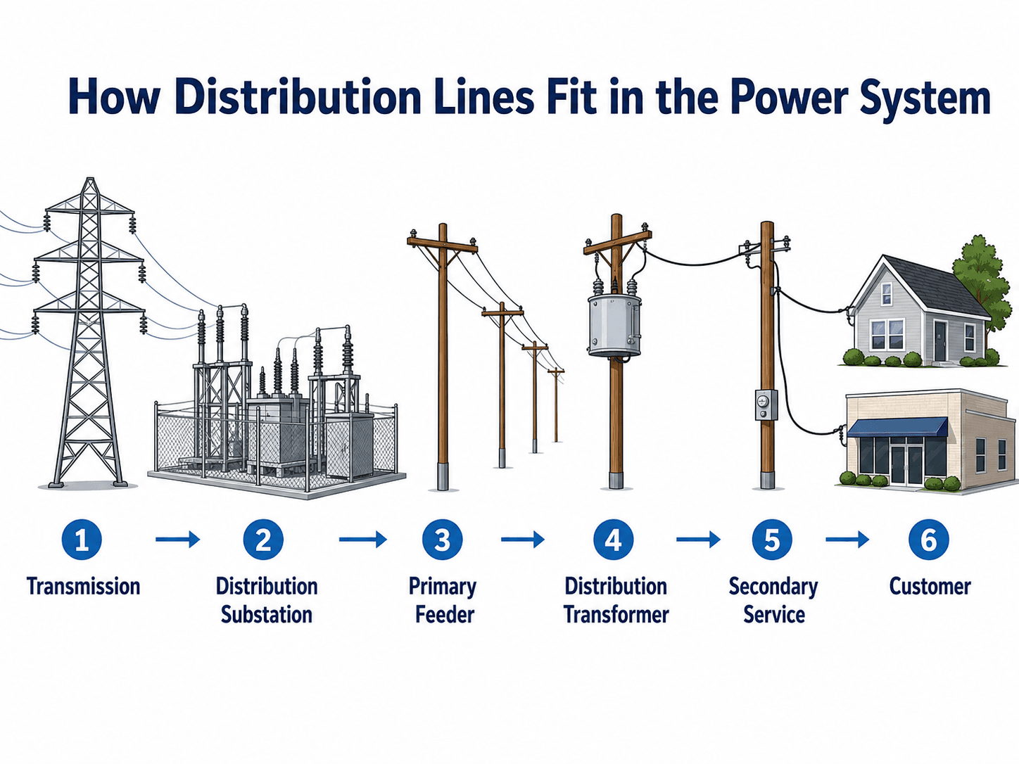
Read the diagram from left to right. The important transition is from bulk power delivery to local distribution: voltage is reduced, the network branches into feeders and laterals, and service connections become customer-specific.
What Are Distribution Lines?
Distribution lines are the overhead or underground circuits that deliver electric power across local service areas after voltage has been reduced from transmission or subtransmission levels. They are normally supplied by a distribution substation and arranged as feeders, laterals, taps, and service connections. The visible power lines along streets are often distribution lines, especially when they include pole-mounted transformers serving nearby customers.
A useful way to think about a distribution line is as the customer-facing edge of the power grid. Transmission lines move bulk power over long distances. Distribution lines divide that power into smaller local paths, regulate voltage closer to customers, isolate faults, and connect individual homes, businesses, pumps, schools, factories, and critical facilities.
Not every line on a pole is a distribution line. Some pole routes may be subtransmission, communications, street lighting, or service conductors. Distribution identification depends on voltage class, equipment, utility configuration, and how the circuit is connected.
Typical Distribution Line Voltage Levels
Distribution line voltage depends on utility practice, load density, feeder length, equipment standards, and whether the circuit is primary or secondary distribution. Primary distribution is generally medium voltage from the substation to distribution transformers. Secondary distribution is the lower-voltage system after the transformer that serves customer equipment.
| Power system level | Typical role | Common engineering notes |
|---|---|---|
| Transmission | Moves bulk power over long distances between generation, major substations, and regional load centers. | Uses high voltage to reduce losses and carry large amounts of power over long routes. |
| Subtransmission | Transfers power between transmission substations and distribution substations in some utility systems. | May look similar to larger distribution or smaller transmission depending on voltage and construction. |
| Primary distribution | Feeds neighborhoods, commercial areas, rural loads, and local transformers from a distribution substation. | Commonly medium voltage; many U.S. distribution systems are below 34 kV, though exact values are utility-specific. |
| Secondary distribution | Connects transformer secondary terminals to customer service equipment. | Common customer service levels include residential and commercial low-voltage services, depending on region and building type. |
The key point is that “distribution” does not always mean “low voltage.” Primary distribution conductors can still be dangerous medium-voltage circuits. The voltage becomes customer-level only after a distribution transformer steps it down.
Primary vs Secondary Distribution Lines
Distribution systems usually have two major electrical levels: primary distribution and secondary distribution. Primary distribution carries medium-voltage power from the substation through feeders and laterals. Secondary distribution carries lower-voltage power from a distribution transformer to the customer service point.
| Part of the distribution system | Typical role | What engineers review |
|---|---|---|
| Primary feeder | Carries medium-voltage power from the distribution substation into the service area. | Feeder loading, voltage drop, protection zones, switching points, regulator placement, and capacitor bank effects. |
| Lateral or tap | Branches from the main feeder to serve smaller load groups, neighborhoods, or individual transformers. | Fuse coordination, conductor size, load growth, vegetation exposure, and outage impact if the lateral faults. |
| Distribution transformer | Steps primary voltage down to secondary voltage near the customer load. | Transformer kVA rating, loading diversity, secondary voltage, protection, grounding, and service connection arrangement. |
| Secondary service | Connects the transformer secondary to residential, commercial, or small industrial service equipment. | Voltage drop, service conductor rating, connection condition, phase balance, and customer-side load changes. |
This distinction matters because a distribution problem may occur on either side of the transformer. A primary feeder issue can affect many customers, while a secondary service issue may affect one building, one service drop, or a small group of customers on the same transformer.
Main Components of Distribution Lines
A distribution line is a collection of conductors, structures, equipment, and protective devices that work together. The exact layout depends on whether the system is overhead or underground, radial or looped, urban or rural, and primary or secondary distribution.
| Component | What it does | Why it matters |
|---|---|---|
| Conductors | Carry current along the feeder, lateral, or secondary service path. | Conductor size and material affect ampacity, voltage drop, losses, sag, and thermal limits. |
| Poles, structures, or underground routes | Support overhead circuits or route underground cables through ducts, trenches, or vaults. | Physical routing controls access, storm exposure, clearances, repair time, and constructability. |
| Insulators and bushings | Separate energized conductors from structures and equipment enclosures. | Insulation failure can cause flashover, leakage paths, or faults during contamination, lightning, or wet conditions. |
| Distribution transformer | Steps primary distribution voltage down to secondary service voltage near customer loads. | Transformer size, location, and loading influence voltage quality, losses, and customer service capacity. |
| Fuse cutout | Protects a lateral, transformer tap, or smaller section of the distribution system. | Correct fuse coordination can isolate a local fault without tripping the entire feeder. |
| Recloser | Interrupts fault current and can automatically reclose after a brief delay. | Improves reliability when faults are temporary and helps divide feeders into protection zones. |
| Voltage regulator | Adjusts voltage along a feeder using tap-changing equipment. | Helps keep customer voltage within acceptable ranges as load and feeder voltage change. |
| Capacitor bank | Supplies reactive power support on the distribution system. | Can improve voltage profile, reduce current, and reduce losses when applied correctly. |
| Switches and sectionalizers | Divide the feeder into sections for isolation, restoration, or maintenance. | Switching flexibility affects outage restoration speed and how many customers are interrupted. |
Distribution Feeder Anatomy
A distribution feeder is the practical circuit structure behind the phrase “distribution line.” Instead of one continuous wire from a substation to every load, the system is built as a main feeder with branching laterals, protective devices, transformers, and customer service connections.
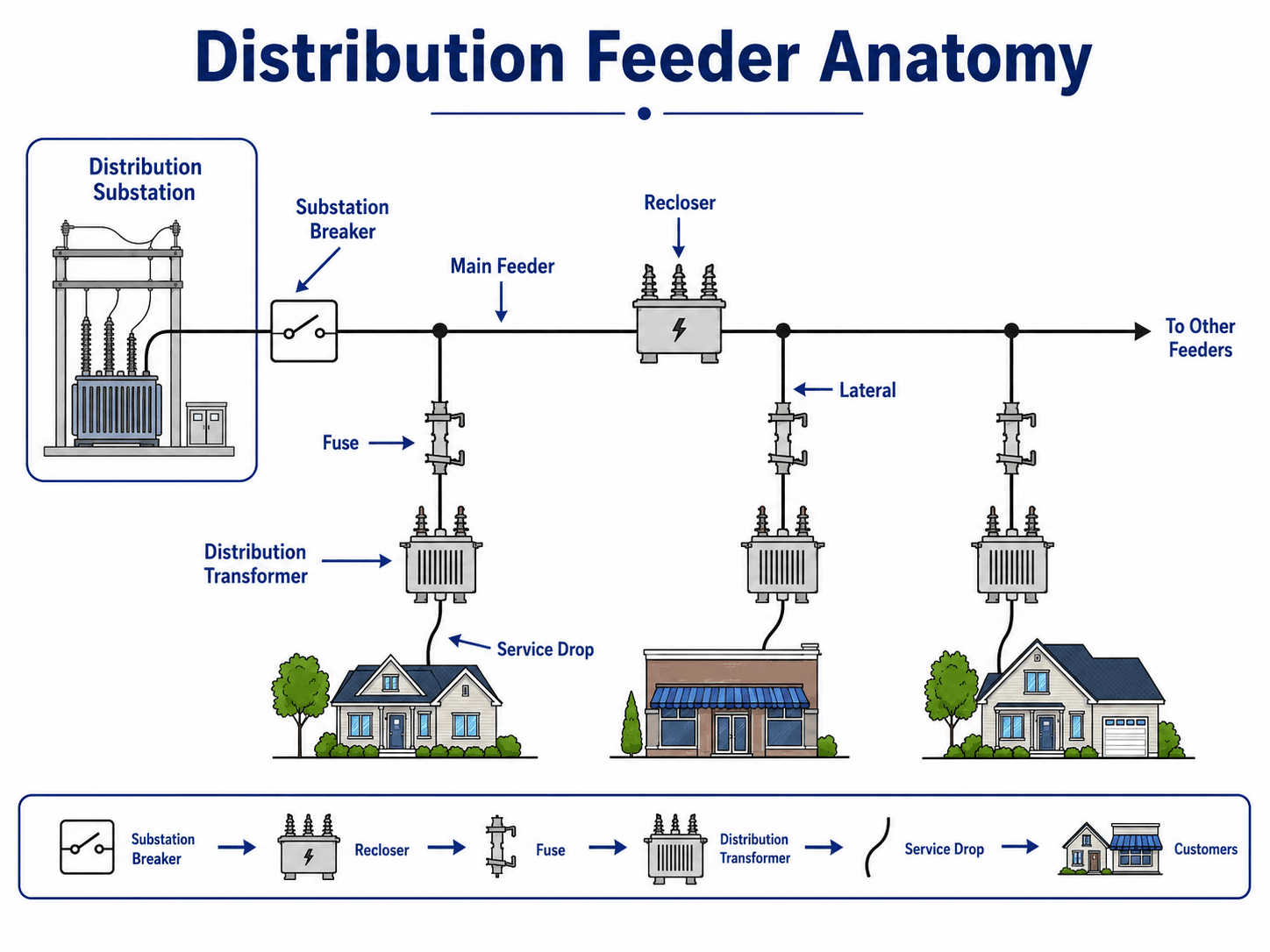
Main feeders and laterals
The main feeder is the backbone of the circuit. It usually carries more load than the branches and may include reclosers, regulators, switches, or capacitor banks. Laterals serve smaller groups of customers and are often protected by fuses so that a lateral fault does not unnecessarily interrupt the entire feeder.
Transformers and service drops
Distribution transformers are placed near customer loads to step primary voltage down to usable secondary voltage. A service drop or service lateral then connects the secondary side of the transformer to the customer service entrance. This local connection is where utility equipment and customer electrical systems meet.
Radial, Looped, and Network Distribution Line Layouts
Distribution lines are not always arranged the same way. The feeder layout affects cost, protection, restoration, reliability, and how easily customers can be backfed after a fault or planned outage.
| Configuration | How it works | Engineering tradeoff |
|---|---|---|
| Radial distribution | Power normally flows from one source through one main feeder path toward downstream loads. | Simple and common, but a fault upstream can interrupt all downstream customers until isolation or repair occurs. |
| Open-loop distribution | Two feeder paths may be available, but one tie point is normally open during normal operation. | Improves restoration options, but switching and protection must be reviewed when the circuit is reconfigured. |
| Network distribution | Multiple sources and interconnected paths supply dense load areas, often in urban systems. | Can improve reliability but requires more complex protection, operations, equipment, and planning. |
Radial systems are easier to understand and protect, which is why they are common. Looped and networked systems can reduce outage impact, but they add operational complexity because the direction and magnitude of power flow can change after switching.
Distribution Lines vs Transmission Lines
The easiest way to separate distribution lines from transmission lines is to look at purpose, voltage class, structure size, and customer proximity. Transmission lines move bulk power across long distances. Distribution lines move power through local service areas and connect to transformers that serve customer loads.
| Comparison point | Transmission line | Distribution line |
|---|---|---|
| Main purpose | Move large blocks of power from generation or regional substations across long distances. | Deliver stepped-down power locally from distribution substations toward customer loads. |
| Typical location | Regional corridors, utility rights-of-way, interconnections, and high-capacity routes. | Neighborhoods, commercial districts, industrial parks, rural roads, and local utility easements. |
| Equipment appearance | Large towers or heavy poles, wide conductor spacing, and high-voltage insulation. | Wood poles, compact structures, distribution transformers, fuses, reclosers, and service drops. |
| Primary engineering concern | Bulk power transfer, stability, long-distance losses, right-of-way, and high-voltage protection. | Voltage regulation, customer reliability, fault isolation, load growth, vegetation, and maintenance access. |
Quick visual clues
Visual clues can help a learner understand the difference, but they should not be treated as official identification. A pole-mounted transformer, service drops to buildings, fuse cutouts, and compact pole-top equipment often indicate distribution. Large lattice towers, long rights-of-way, and very wide conductor spacing often indicate transmission or subtransmission.
Voltage Drop and Voltage Regulation on Distribution Lines
Voltage drop is one of the most important engineering issues on a distribution feeder. As load current flows through conductor impedance, voltage decreases along the circuit. Customers near the end of a long, heavily loaded feeder can see lower voltage than customers near the substation unless the system is designed and regulated correctly.
This simplified relationship shows why feeder voltage is controlled by load current \(I\), conductor resistance \(R\), conductor reactance \(X\), and load power factor angle \(\phi\). Real distribution studies may use load flow software, unbalanced phase modeling, transformer tap settings, voltage regulator controls, capacitor banks, and detailed conductor data.
- \(I\) Load current in amperes; higher current increases voltage drop and conductor heating.
- \(R\) Conductor resistance; strongly affects real power losses and voltage drop on long feeders.
- \(X\) Conductor reactance; important for AC voltage drop, reactive power flow, and feeder voltage profile.
- \(\phi\) Load power factor angle; changes how resistance and reactance contribute to voltage drop.
Distribution feeders are often unbalanced because single-phase laterals, rooftop solar, EV charging, small commercial loads, and residential diversity do not load each phase equally. A three-phase average can hide a weak phase at the end of a feeder.
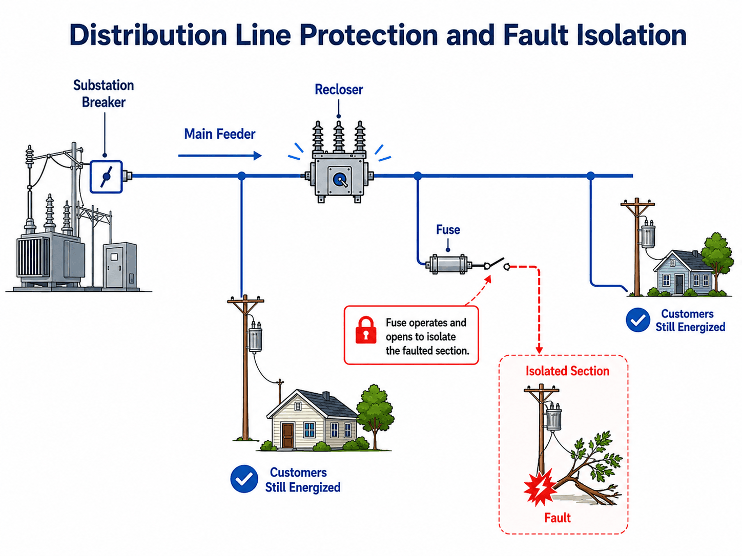
Distribution Line Protection and Fault Isolation
Distribution protection is designed to isolate faults while keeping as many customers energized as practical. A substation breaker may protect the feeder as a whole, while downstream reclosers, fuses, sectionalizers, and switches divide the circuit into smaller protection zones.
Temporary faults and reclosers
Many distribution faults are temporary, such as a branch brushing a conductor or wildlife contact that clears quickly. A recloser can interrupt the fault current, wait briefly, and re-energize the circuit. If the fault has cleared, service is restored without a permanent outage.
Permanent faults and selective isolation
If a fault is permanent, the goal is selective isolation. A downstream fuse or device should operate before a larger upstream device trips more customers than necessary. This requires careful coordination of device ratings, time-current curves, available fault current, and feeder topology.
Fuse-saving and fuse-isolating strategies
Utilities may choose different coordination philosophies. A fuse-saving strategy attempts to clear temporary faults with an upstream recloser before a lateral fuse melts. A fuse-isolating strategy accepts that a downstream fuse may operate for a lateral fault so the main feeder stays energized. The right approach depends on utility reliability goals, crew response, customer density, fault history, and equipment settings.
Overhead vs Underground Distribution Lines
Distribution lines can be built overhead on poles or underground in duct banks, direct-buried cable routes, or vault systems. Underground distribution can reduce exposure to wind, trees, and some visual impacts, but it does not eliminate failures. It also changes how faults are located and repaired.
| Design factor | Overhead distribution | Underground distribution |
|---|---|---|
| Storm exposure | More exposed to wind, ice, lightning, trees, vehicles, and wildlife. | Less exposed to overhead storm damage but still vulnerable to flooding, digging, insulation failure, and equipment vault issues. |
| Fault location | Many faults are visible during patrol or drone inspection. | Faults may require cable testing, locating equipment, excavation, and specialized crews. |
| Restoration time | Often faster when access is available and damage is visible. | Can be slower when the cable section must be located, exposed, repaired, and re-energized. |
| Cost and constructability | Usually less expensive and easier to modify for load growth. | Usually higher installation cost and more complex coordination with other underground utilities. |
The best choice depends on reliability goals, environment, customer density, wildfire exposure, aesthetics, soil conditions, flood risk, construction cost, and repair access. A dense urban network and a rural feeder do not have the same economic or operational constraints.
Common Distribution Line Outage Causes
Distribution outages often come from local physical conditions rather than from the bulk power system. Because distribution lines are close to trees, roads, buildings, animals, and customer load changes, many reliability issues are field-maintenance problems as much as electrical analysis problems.
| Outage cause | More common on | What usually happens |
|---|---|---|
| Tree contact or falling branches | Overhead distribution | Can create temporary faults, permanent faults, broken conductors, or repeated recloser operations. |
| Lightning and switching surges | Overhead distribution and exposed equipment | May cause flashover, arrester operation, transformer damage, or insulation stress. |
| Wildlife contact | Overhead structures and pad-mounted equipment | Can bridge energized parts and cause protective devices to operate. |
| Underground cable insulation failure | Underground distribution | Often creates a permanent fault that requires cable locating, testing, excavation, and repair. |
| Vehicle impact | Roadside poles, cabinets, and pad-mounted transformers | Can damage poles, guy wires, switch cabinets, transformers, and service equipment. |
| Overloaded equipment | Both overhead and underground systems | Can cause heating, voltage drop, accelerated aging, transformer failure, or nuisance operations. |
How Engineers Model Distribution Lines
Distribution line models help engineers evaluate whether a feeder can serve load reliably while keeping voltage and equipment loading within acceptable limits. Compared with transmission models, distribution models often need more detail on single-phase laterals, unbalanced loading, customer diversity, transformers, regulators, and switching configurations.
| Modeling item | Why it is included | Common review question |
|---|---|---|
| Feeder and lateral impedance | Determines voltage drop, losses, and fault current along each section. | Are conductor types, lengths, and phases modeled correctly? |
| Load allocation | Assigns customer demand to transformers, laterals, and phases. | Does the model reflect peak load, diversity, seasonal behavior, and future growth? |
| Phase imbalance | Captures unequal loading across phases from single-phase services and laterals. | Is one phase carrying significantly more load or experiencing worse voltage? |
| Voltage regulators and capacitor banks | Represent equipment that changes voltage and reactive power behavior. | Are control settings, time delays, and switching states realistic? |
| Fault current and protection devices | Supports coordination of breakers, reclosers, fuses, and sectionalizers. | Will the intended device operate for faults at the end of each lateral? |
| Distributed energy resources | Accounts for rooftop solar, batteries, and other sources that can change net load and power direction. | Can voltage rise, reverse power flow, or protection sensitivity become a problem? |
A clean one-line diagram is useful for learning, but a real distribution model must account for phase-by-phase loading, switching state, transformer connections, regulator controls, and feeder topology.
Modern Distribution Automation and DER Impacts
Modern distribution lines increasingly use automated switches, reclosers, sensors, communications, and control systems to improve reliability. These systems can help locate faults, isolate the faulted section, and restore service to unfaulted sections more quickly than manual switching alone.
Distributed energy resources also change how distribution lines behave. Rooftop solar, batteries, EV charging, and local generation can affect voltage rise, reverse power flow, transformer loading, phase imbalance, and protection settings. A feeder that was originally designed for one-way power flow may need additional review when distributed generation becomes significant.
Distribution Line Engineering Review Checklist
A strong distribution line review looks at more than conductor size. Engineers review the electrical loading, protection scheme, voltage profile, physical exposure, maintainability, and restoration strategy as one connected system.
Start with the feeder source and voltage class, trace the main feeder and laterals, identify transformers and protective devices, compare load current against conductor and equipment ratings, review voltage profile at far-end loads, then check whether faults can be isolated without unnecessary customer interruptions.
| Distribution line check | What to look for | Why it matters |
|---|---|---|
| Voltage level and feeder source | Confirm whether the circuit is primary distribution, secondary distribution, or subtransmission. | Voltage class affects equipment ratings, clearances, protection, insulation, and how the line should be modeled. |
| Conductor and equipment loading | Compare peak load, seasonal load, and future load growth against conductor, transformer, switch, and protective device ratings. | Overloaded equipment increases losses, heating, voltage drop, and failure risk. |
| Voltage profile | Review voltage at the substation, mid-feeder locations, long laterals, and far-end customers. | Voltage issues often appear at the end of long feeders or on heavily loaded single-phase laterals. |
| Protection coordination | Check substation breaker, recloser, fuse, and sectionalizing behavior for expected fault current levels. | Good coordination isolates the faulted section while keeping more customers in service. |
| Field exposure | Review vegetation, pole condition, animal exposure, flood zones, wildfire exposure, road crossings, and access constraints. | Distribution reliability is often controlled by local physical conditions rather than ideal one-line diagrams. |
| Switching and restoration | Identify normally open points, tie switches, alternate feeds, and crew access points. | Restoration planning determines how quickly customers can be re-energized after a fault or equipment failure. |
Engineering Judgment and Field Reality
Distribution lines are strongly affected by conditions that are difficult to capture in a simple schematic. Vegetation growth, aging pole hardware, customer load changes, poor phase balance, weather exposure, wildlife, construction damage, and underground cable condition can all change how a feeder performs over time.
Engineers also need to think about restoration, not just normal operation. A feeder that looks acceptable in a steady-state model may still create poor customer outcomes if it has limited switching options, long laterals with many customers, inaccessible equipment, or fuse coordination that causes more interruptions than necessary.
The most reliable distribution design is not always the one with the most equipment. Additional reclosers, fuses, regulators, and switches can improve performance only when they are coordinated, maintained, accessible, and matched to the actual feeder topology.
When This Breaks Down
Simplified explanations of distribution lines break down when the feeder is no longer a simple radial path from one substation to one load area. Real distribution systems may include open-loop switching, distributed energy resources, voltage regulators, capacitor banks, single-phase laterals, and changing load patterns.
- Long rural feeders can have voltage drop and protection sensitivity issues that do not appear on short urban circuits.
- Distributed solar and battery systems can create bidirectional power flow, changing voltage regulation and protection assumptions.
- Underground circuits may have fewer momentary interruptions but longer repair times when a cable fault occurs.
- Heavy single-phase loads can unbalance phases and create customer voltage complaints even when the feeder average looks acceptable.
- Regulator line-drop compensation may behave differently after switching, feeder reconfiguration, or DER output changes.
- Protection settings that work at peak load may not behave the same way during light load, alternate switching, or high distributed generation output.
Common Distribution Line Mistakes and Misconceptions
Many distribution line explanations stop at “power lines bring electricity to customers.” That is true, but incomplete. A distribution line is an engineered circuit with voltage limits, thermal limits, fault duty, coordination rules, physical supports, and maintenance requirements.
- Assuming all neighborhood power lines are low voltage: primary distribution conductors may still be medium voltage until they reach a distribution transformer.
- Ignoring the lateral: many customer outages originate on lateral branches, not on the main feeder leaving the substation.
- Treating underground as failure-proof: underground circuits reduce some exposure but can be harder to inspect, locate, excavate, and repair.
- Reviewing voltage without load cases: voltage profile changes with load level, power factor, switching state, distributed generation, and regulator control settings.
- Looking at protection devices individually: fuses, reclosers, and breakers must be reviewed as a coordinated sequence, not as isolated components.
Do not identify a distribution line only by appearance. Pole height, conductor count, and visible transformers are clues, but the actual circuit function, voltage, and ownership determine what the line is.
Useful References and Design Context
Distribution line design and operation depend on utility standards, equipment ratings, local construction requirements, protection studies, and reliability objectives. Public primers are useful for understanding the system role, while final design decisions normally depend on utility-specific standards and project requirements.
- U.S. Department of Energy: Electric Transmission & Distribution and Protective Measures provides a clear public overview of transmission, distribution, substations, distribution feeders, system threats, vegetation management, automated distribution management, and grid hardening measures.
- Utility standards: Construction details, grounding, clearances, pole framing, underground routing, transformer sizing, and approved equipment are usually controlled by the serving utility and project-specific requirements.
- Engineering studies: Load flow, short-circuit, protection coordination, voltage regulation, and reliability reviews help determine whether a distribution line can serve the required load safely and reliably.
Frequently Asked Questions
A distribution line is the part of the electric power system that carries electricity from a distribution substation toward end users. It usually includes primary feeders, laterals, distribution transformers, secondary service conductors, and protective devices that deliver power locally.
Transmission lines move large amounts of power over long distances at high voltage, while distribution lines move stepped-down power over shorter distances to neighborhoods, commercial areas, and local loads. Distribution lines are usually closer to customers and include more transformers, fuses, reclosers, laterals, and service connections.
Distribution voltage depends on the utility and system design. Primary distribution is commonly medium voltage, while secondary distribution is the lower-voltage service level supplied after a distribution transformer. In the United States, many distribution systems operate below 34 kV, but exact values vary by utility and location.
The main parts of a distribution line include conductors, poles or underground cable routes, insulators, switches, reclosers, fuses, voltage regulators, capacitor banks, distribution transformers, laterals, and service drops. The exact equipment depends on whether the line is overhead, underground, radial, looped, or part of a denser network.
Distribution line outages are commonly caused by trees, storms, lightning, wildlife, equipment aging, overloaded components, underground cable faults, broken connectors, vehicle impacts, or protective devices operating during a fault. Because distribution lines are close to customers and exposed to local conditions, field maintenance and vegetation management are major reliability factors.
Summary and Next Steps
Distribution lines are the local delivery circuits that connect distribution substations to customer loads through feeders, laterals, transformers, protective devices, and secondary services. They are the part of the power system most customers physically see and the part most directly tied to local outage experience.
The most important engineering checks are voltage profile, load current, conductor and transformer capacity, protection coordination, switching flexibility, outage exposure, and field access. A good distribution review combines electrical analysis with practical knowledge of vegetation, weather, underground cable repair, distributed energy resources, and restoration strategy.
Where to go next
Continue your learning path with related Turn2Engineering resources.
-
Power Systems Engineering
Build the broader context for generation, transmission, distribution, protection, and grid operation.
-
Load Flow Analysis
Learn how engineers evaluate voltage profile, line loading, transformer loading, and losses in power systems.
-
Power System Efficiency
See how distribution losses, voltage drop, and equipment performance affect overall power delivery efficiency.