Key Takeaways
- Core idea: Surge arresters limit transient overvoltages by conducting surge current to ground before equipment insulation is overstressed.
- Engineering use: They protect transformers, line entrances, switchgear, cable transitions, and overhead equipment from lightning and switching surges.
- What controls it: Arrester performance depends on MCOV, rated voltage, residual voltage, TOV withstand, energy duty, grounding quality, and lead length.
- Practical check: A correctly rated arrester can still underperform if it is too far from the protected terminal or connected through long, inductive leads.
Table of Contents
Introduction
Surge arresters are power-system protection devices that limit damaging transient overvoltages from lightning, switching events, and other surge conditions. They normally behave like high-impedance devices, then conduct surge current to ground when voltage rises above a protective level, helping keep transformers, switchgear, cables, and line insulation from being overstressed.
Where Surge Arresters Fit in a Power System
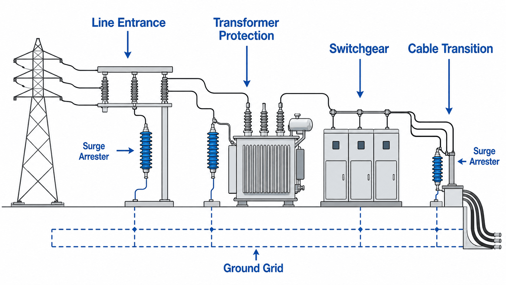
Notice that the arrester is not placed randomly on the system. It is located at points where surge voltage can enter, reflect, or stress insulation: line entrances, transformer terminals, switchgear connections, and cable transitions.
What Is a Surge Arrester?
A surge arrester is an overvoltage protection device used on electric power systems. Its job is to limit short-duration voltage spikes before they exceed the insulation withstand of connected equipment. In modern medium-voltage and high-voltage applications, most arresters use metal-oxide varistor behavior, meaning their resistance changes sharply with voltage.
Under normal system voltage, the arrester should carry very little current. During a lightning impulse or switching surge, the arrester becomes conductive and provides a path to ground. After the transient passes, it returns to a mostly non-conducting state so the power system can continue operating.
A surge arrester is an overvoltage protection device, not an overcurrent protection device. Fuses, relays, and circuit breakers isolate fault current; surge arresters limit voltage stress from fast transients.
How Surge Arresters Work During a Transient Surge
The protective behavior of a surge arrester comes from its nonlinear voltage-current characteristic. At ordinary operating voltage, the arrester acts like a high-impedance path. When a transient overvoltage appears, the arrester conducts heavily enough to clamp the voltage and discharge surge energy toward ground.
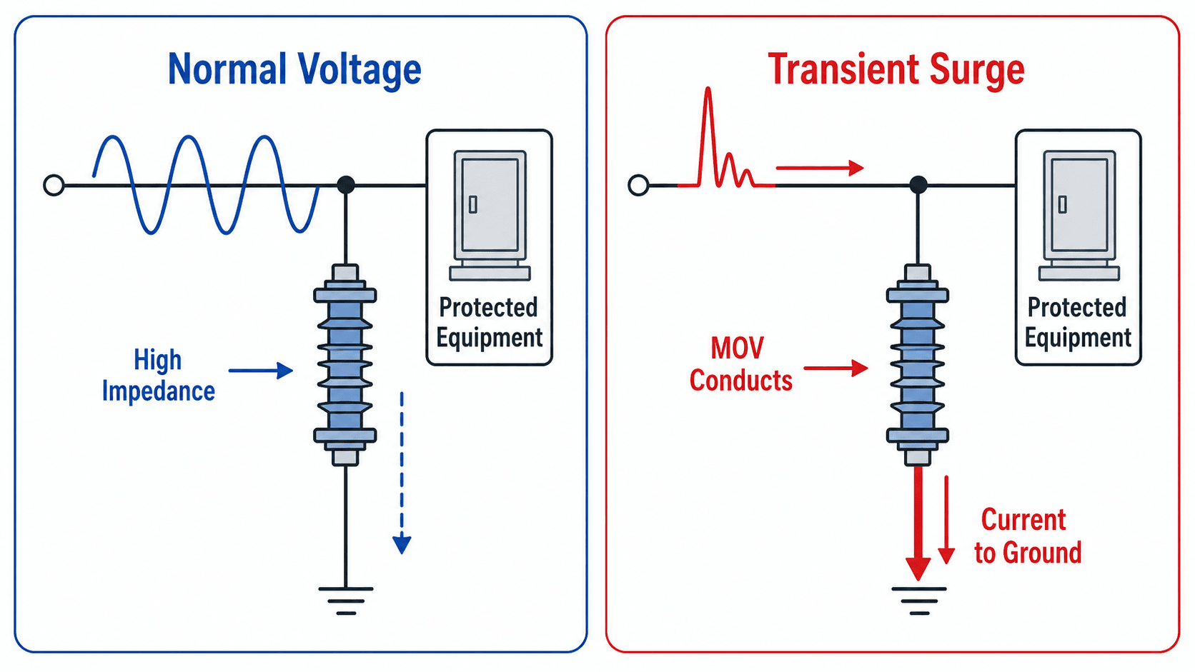
Normal operating voltage
In normal service, the arrester must tolerate the system voltage continuously without overheating. This is why maximum continuous operating voltage, often abbreviated MCOV, is one of the most important selection values. The arrester should be connected and ready, but it should not behave like a continuous load.
Surge condition
When a lightning or switching impulse raises the line voltage, the metal-oxide blocks conduct. The arrester does not make the surge disappear; it limits the voltage seen by the protected equipment to a lower residual voltage. That remaining voltage must still be coordinated with transformer, cable, bushing, or switchgear insulation withstand.
Return to service
After the surge energy is discharged, the arrester must stop conducting significant current. If the system voltage or temporary overvoltage remains too high, the arrester may continue to dissipate energy and overheat. That is why arrester selection is tied to system grounding, temporary overvoltage behavior, and fault-clearing practices.
What Surge Arresters Protect Against
Surge arresters protect against fast overvoltage events that can puncture insulation, flash over bushings, damage transformer windings, or accelerate aging in cables and connected equipment. The two major surge categories are lightning surges and switching surges, but temporary overvoltage also matters because it affects whether the arrester can survive the event.
| Surge condition | Typical source | Why it matters for surge arresters |
|---|---|---|
| Lightning impulse | Direct or nearby lightning strike, backflashover, induced voltage on overhead lines | Produces very steep voltage waves that can overstress transformer bushings, line insulation, cable terminals, and substation equipment. |
| Switching surge | Line energization, capacitor switching, breaker operation, trapped charge, load rejection | Can involve longer-duration energy than a lightning impulse, especially on higher-voltage systems or long lines. |
| Temporary overvoltage | Ground fault on an ungrounded or impedance-grounded system, load rejection, ferroresonance, neutral shift | May last too long for the arrester to absorb like a transient surge; the arrester must be rated to withstand expected TOV conditions. |
| Traveling-wave reflections | Cable transitions, open points, transformer terminals, impedance changes | Can raise local voltage stress at a specific equipment terminal even when the original surge entered elsewhere. |
What surge arresters do not protect against
Surge arresters are not intended to correct every electrical problem. They do not replace overcurrent protection, voltage regulation, grounding design, insulation maintenance, or protection coordination studies.
- Overloads and short circuits: these are handled by fuses, relays, reclosers, and circuit breakers.
- Sustained voltage regulation problems: an arrester is not a tap changer, regulator, or capacitor-control device.
- Harmonics and power quality distortion: surge arresters are not filters for waveform distortion.
- Poor grounding by itself: an arrester needs a low-impedance ground path; it does not fix a weak grounding system.
- Incorrect insulation coordination: an arrester must be selected and located so the actual equipment terminal voltage remains acceptable.
The protected equipment does not see the arrester datasheet value alone. It sees the arrester residual voltage plus voltage developed across leads, grounding impedance, and physical separation between the arrester and the equipment terminal.
Types of Surge Arresters: Distribution, Intermediate, Station, and Line Arresters
Surge arrester names usually describe the duty level and application location. The exact product categories vary by manufacturer and standard, but engineers generally think in terms of distribution, intermediate, station, and line arrester applications.
| Arrester type | Common application | Engineering note |
|---|---|---|
| Distribution class arrester | Distribution feeders, pole-top transformers, reclosers, laterals, service-area equipment | Common in overhead distribution systems where lightning exposure, feeder reliability, and equipment cost must be balanced. |
| Intermediate class arrester | Substations, industrial systems, larger distribution equipment, moderate energy-duty locations | Used where the duty is heavier than typical distribution protection but not as severe as major station-class applications. |
| Station class arrester | Substation transformers, high-value equipment, transmission substations, major bus or line entrance points | Selected where protective margin, energy capability, and equipment value justify a more robust arrester. |
| Line arrester | Overhead transmission or distribution structures, lightning-prone spans, tower locations with poor shielding or footing resistance | Installed on lines to reduce flashovers and improve lightning performance before surges reach substation equipment. |
| Riser-pole or cable-transition arrester | Overhead-to-underground cable transitions and feeder exits | Important because cable insulation and terminations can be vulnerable to reflected traveling waves and steep-front surges. |
Surge arrester vs lightning arrester vs surge protector
“Lightning arrester” is often used casually for older or lightning-focused applications, while “surge arrester” is broader and better for power-system overvoltage protection. A low-voltage surge protective device, or SPD, may protect building electrical panels and electronic equipment, but medium-voltage and high-voltage surge arresters are selected and applied using power-system insulation coordination principles.
How Engineers Select Surge Arresters
Surge arrester selection is a coordination problem. The arrester must survive normal and abnormal system voltage, conduct enough surge current during transients, and limit the protected equipment voltage below its insulation withstand with adequate margin.
| Selection factor | Why it matters | Engineering implication |
|---|---|---|
| System voltage | The arrester must remain stable at the actual phase-to-ground voltage it sees in service. | Nominal voltage alone is not enough; grounding method and operating range affect the correct arrester rating. |
| MCOV | Maximum continuous operating voltage defines how much voltage the arrester can withstand continuously. | Too low an MCOV can cause overheating or premature failure during normal or slightly abnormal operation. |
| Temporary overvoltage capability | TOV events last longer than surge impulses and can create sustained energy stress. | Ungrounded, impedance-grounded, or resonant-grounded systems may require special review. |
| Protective level | The arrester limits voltage to a residual or discharge voltage during surge current flow. | The residual voltage must be coordinated with transformer BIL, bushing withstand, cable insulation, and switchgear ratings. |
| Energy duty | Repeated surges or long switching surges can deposit significant energy in the arrester. | High-exposure lines, capacitor banks, and transmission applications may need higher energy capability. |
| Housing and environment | Outdoor arresters face UV, rain, pollution, salt, wildlife, and mechanical stress. | Creepage distance, housing material, sealing, and contamination performance affect long-term reliability. |
| Fault-current capability | An arrester failure must be contained safely under system short-circuit conditions. | Pressure relief, disconnect behavior, and fault-current rating should match the installation location. |
MCOV vs rated voltage vs TOV
One of the most common surge arrester mistakes is treating voltage terms as interchangeable. MCOV, rated voltage, and temporary overvoltage capability describe different parts of arrester behavior.
| Term | Plain-English meaning | Common mistake |
|---|---|---|
| MCOV | The maximum voltage the arrester can withstand continuously without excessive heating or conduction. | Selecting MCOV too low for the actual phase-to-ground voltage or system operating range. |
| Rated voltage | The arrester duty rating used for application and test classification. | Assuming it is simply the same as nominal system voltage. |
| TOV capability | The arrester’s ability to withstand temporary overvoltage for a limited time. | Ignoring ground-fault overvoltage on ungrounded or impedance-grounded systems. |
| Residual voltage | The voltage remaining across the arrester while surge current is flowing. | Assuming the arrester reduces voltage to zero instead of a finite protective level. |
The best arrester rating is not simply the lowest protective voltage. It is the rating that provides protective margin while still surviving continuous voltage, temporary overvoltage, switching duty, environmental exposure, and system grounding behavior.
How to Read a Surge Arrester Datasheet
A surge arrester datasheet tells engineers whether the device can survive the system and protect the equipment. The most important values are not just the voltage class; they include continuous voltage withstand, discharge voltage, energy duty, temporary overvoltage capability, and failure containment ratings.
| Datasheet item | What it means | Why it matters in design review |
|---|---|---|
| Rated voltage | Duty rating used to classify and apply the arrester on an AC system. | Helps match the arrester to system voltage and grounding conditions, but should not be used alone. |
| MCOV | Maximum continuous operating voltage the arrester can withstand. | Confirms the arrester will not overheat under normal operating voltage. |
| Nominal discharge current | Standardized surge current level used for testing or class comparison. | Helps compare arrester duty level and expected surge performance. |
| Residual or discharge voltage | Voltage across the arrester while it is conducting surge current. | Defines the protective level that must be compared with transformer, cable, and switchgear insulation withstand. |
| TOV curve or capability | Temporary overvoltage the arrester can withstand for limited time durations. | Critical for ground-fault conditions, neutral shift, and abnormal system operation. |
| Energy rating or energy handling | Ability to absorb surge energy without thermal failure. | Important for switching surges, long lines, capacitor banks, repeated surges, and high-exposure installations. |
| Pressure relief or fault-current rating | Failure containment performance under fault-current conditions. | Important for equipment safety, personnel safety, and proper application at high fault-current locations. |
| Creepage distance and housing type | External insulation path and material suitability for outdoor service. | Controls performance under pollution, salt, moisture, UV exposure, and contamination. |
If the datasheet review stops at nominal voltage, the selection is incomplete. A serious review checks MCOV, TOV capability, residual voltage, energy duty, fault-current capability, and environmental suitability together.
Surge Arresters and Insulation Coordination
Surge arresters protect equipment by keeping surge stress below the equipment insulation withstand. This is called insulation coordination. The arrester does not remove all voltage; it limits the voltage to a protective level that must be low enough for the transformer, cable, bushing, switchgear, or line insulation being protected.
Equipment surge stress is approximately the arrester residual voltage plus voltage added by leads, grounding impedance, and separation between the arrester and the protected terminal.
| Coordination item | What to compare | Why it matters |
|---|---|---|
| Transformer BIL | Transformer basic impulse level compared with arrester protective level and installation voltage rise. | Confirms that winding and bushing insulation have enough margin during impulse events. |
| Cable termination withstand | Cable and termination insulation compared with local surge voltage at the transition. | Cable transitions can reflect traveling waves and create high terminal stress. |
| Switchgear insulation level | Switchgear impulse withstand compared with residual voltage and grounding effects. | Helps prevent internal flashover and insulation aging in metal-enclosed equipment. |
| Lead and ground voltage | Additional voltage caused by arrester lead inductance and grounding impedance. | Can erase protective margin even when the arrester datasheet rating looks acceptable. |
For practical design, engineers review arrester protective level alongside equipment insulation ratings, surge source, grounding layout, and physical installation. A station-class arrester with strong datasheet performance can still provide weak protection if it is installed too far away from the equipment terminal.
Senior Engineer Surge Arrester Review Checklist
A surge arrester review should move from system conditions to protected-equipment coordination, then to installation quality. This checklist gives a practical review path for substation, feeder, transformer, or cable-transition applications.
Start with system voltage and grounding method. Confirm MCOV and TOV capability. Check the protective level against equipment insulation withstand. Review energy duty and discharge current rating. Then confirm that the arrester is physically close to the protected equipment with short leads and a direct ground path.
| Review check | What to look for | Why it matters |
|---|---|---|
| System grounding | Effectively grounded, impedance grounded, ungrounded, or resonant grounded system behavior | Grounding method affects temporary overvoltage and whether the arrester can survive abnormal voltage conditions. |
| MCOV margin | Continuous phase-to-ground voltage at the arrester terminals, including operating range | Insufficient MCOV can turn a protection device into a heat-stressed component during normal operation. |
| Insulation coordination | Arrester residual voltage compared with transformer BIL, cable withstand, bushing rating, and switchgear insulation level | The arrester must limit voltage below the level likely to damage the protected equipment. |
| Energy exposure | Lightning density, line length, switching duty, capacitor banks, and repeated events | Energy duty determines whether the arrester can absorb expected surges without thermal damage. |
| Lead length | Short, straight connections from line to arrester and arrester to ground | Long leads add inductive voltage during steep surge current, reducing the real protection margin. |
| Ground path | Direct connection to ground grid, pole ground, or station grounding system | A poor ground path increases local voltage rise and can transfer stress back to the protected equipment. |
| Environmental suitability | Pollution, salt fog, altitude, wildlife, mechanical exposure, UV, and housing condition | Outdoor service conditions can drive creepage, housing, sealing, and maintenance requirements. |
Installation Quality: Good vs Poor Arrester Protection
Surge arrester placement is as important as the selected rating. A datasheet may show an excellent protective level, but the protected equipment may experience a higher voltage if the arrester is far away, connected through long loops, or tied to a weak grounding path.
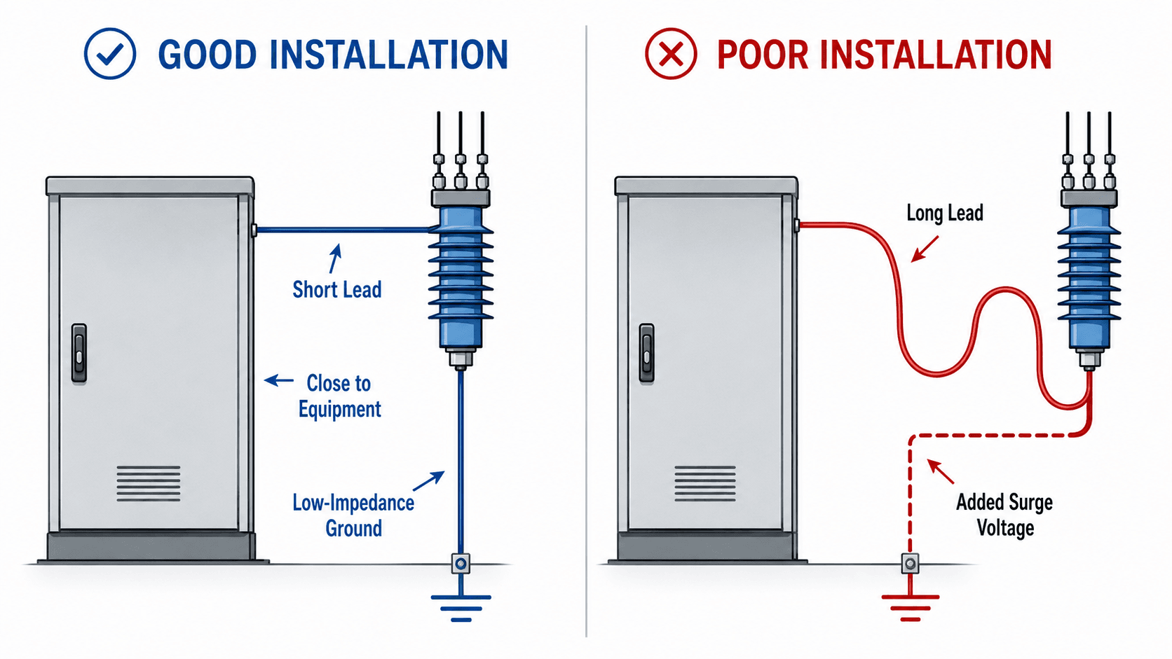
Why lead length matters
Surge current rises very quickly. Even a conductor that looks small compared with the physical substation can add significant voltage because of inductance. The longer and more looped the lead, the more voltage can appear between the protected equipment terminal and the arrester ground path during a surge.
Why location matters
The arrester should be installed close to the insulation it is intended to protect. For a transformer, that often means near the transformer terminals or bushings. For a cable transition, it means near the termination where traveling waves can reflect. For a line entrance, it means near the point where the surge enters the station.
Engineering Judgment and Field Reality
In ideal diagrams, the arrester clamps voltage and the equipment remains protected. In real systems, the result depends on grounding, conductor routing, fault-clearing speed, equipment age, contamination, installation workmanship, and how often the system is exposed to lightning or switching events.
| Field condition | What it can change | Practical review question |
|---|---|---|
| Poor station grounding or high pole-ground resistance | Raises local ground potential during a surge | Does the arrester have a short, direct, tested path into the grounding system? |
| Polluted or cracked arrester housing | Increases leakage, tracking, flashover risk, or moisture ingress | Are there visible cracks, contamination bands, burn marks, or signs of water entry? |
| Frequent capacitor or line switching | Can increase repetitive energy duty | Has switching-surge energy been considered, not just lightning impulse protection? |
| Ungrounded or impedance-grounded system | Can increase temporary overvoltage during ground faults | Was TOV withstand reviewed for the actual system grounding method? |
| Long separation from protected equipment | Can reduce the effective protection margin | Is the arrester protecting the terminal that is actually vulnerable, or just a nearby bus point? |
Many arrester problems are not obvious from the one-line diagram. A field walkdown should check physical lead routing, grounding, housing condition, clearance, contamination, and whether the arrester is truly near the insulation it is supposed to protect.
When Surge Arrester Protection Breaks Down
Surge arresters are powerful protection devices, but they are not universal fixes for every voltage or power-quality problem. Protection breaks down when the arrester is misapplied, installed poorly, exposed to conditions beyond its rating, or expected to solve problems that are outside its function.
- Temporary overvoltage exceeds arrester capability: the arrester may overheat if an abnormal system voltage lasts too long.
- Insulation coordination is not checked: the arrester may conduct, but the remaining residual voltage may still be too high for the protected equipment.
- Lead lengths are excessive: added inductive voltage can make the real terminal voltage higher than expected.
- Grounding is weak: surge current needs a low-impedance path; otherwise local voltage rise can stress nearby insulation.
- Wrong problem is being solved: surge arresters do not correct sustained voltage regulation issues, overloads, harmonics, or short-circuit current coordination.
Do not choose a surge arrester only by nominal system voltage. The actual system grounding method, MCOV, temporary overvoltage behavior, protective level, and installation details can control whether the arrester is suitable.
Common Surge Arrester Failure Modes and Inspection Checks
Surge arrester failures can be electrical, thermal, mechanical, or environmental. Some failures are sudden, while others show up as leakage current changes, visible housing damage, tracking marks, or repeated operation of disconnectors or counters.
| Failure or inspection item | Likely cause or concern | What engineers or technicians look for |
|---|---|---|
| Thermal overload | Excessive temporary overvoltage, repeated energy duty, wrong voltage rating | Discoloration, failed disconnector, elevated leakage current, thermal damage, or operation after abnormal voltage events. |
| Moisture ingress | Seal failure, cracked housing, manufacturing defect, aging, mechanical impact | Visible cracks, swelling, tracking, corrosion, unexplained leakage increase, or abnormal infrared scan results. |
| External flashover | Pollution, salt, wet contamination, inadequate creepage, damaged housing | Surface tracking, flash marks, contamination bands, or signs of arcing across the housing. |
| Mechanical damage | Wildlife, vandalism, conductor strain, storm debris, installation damage | Broken sheds, bent brackets, loose connections, displaced ground leads, or damaged terminals. |
| Ground lead issue | Loose connection, corrosion, long path, broken bond, missing ground connection | Disconnected leads, corroded lugs, high-resistance connections, or long loops between arrester and ground grid. |
| Protection underperformance | Long leads, poor ground path, wrong location, uncoordinated protective level | Equipment damage despite the arrester being present, high lead inductance, or arrester installed too far from the protected terminal. |
A practical inspection should confirm housing condition, terminal tightness, ground lead condition, disconnector status, counter or leakage monitor reading, contamination level, wildlife damage, storm damage, and whether the arrester is still close to the equipment it was intended to protect.
Standards, References, and Design Context
Surge arrester application depends on project voltage level, equipment insulation withstand, system grounding, expected surge duty, and manufacturer ratings. Standards help define test requirements, terminology, performance classes, and application expectations, while project specifications and utility standards determine final selection details.
- IEEE C62.11: IEEE standard for metal-oxide surge arresters for AC power circuits covers metal-oxide surge arresters used on AC power circuits above 1 kV and is a strong reference point for understanding arrester performance requirements.
- Related standard families: IEC 60099-4 is also widely associated with metal-oxide surge arresters, especially in international applications.
- Engineering use: For day-to-day application, engineers use these standards together with manufacturer application guides, utility standards, equipment BIL data, grounding details, and project-specific insulation coordination requirements.
Frequently Asked Questions
A surge arrester limits transient overvoltage by switching from a high-impedance state to a conducting state during a surge. It diverts surge current to ground so the voltage across protected equipment, such as a transformer or switchgear lineup, stays below a damaging level.
The terms are often used interchangeably, but surge arrester is the broader engineering term. A lightning arrester mainly refers to protection from lightning impulses, while a surge arrester can also address switching surges and other transient overvoltages in power systems.
MCOV is the maximum continuous operating voltage the arrester can withstand without overheating or conducting excessive current. It is one of the most important selection values because the arrester must survive normal system voltage before it can protect against transient surges.
Surge arresters are normally installed close to the equipment they protect, such as transformer terminals, substation line entrances, switchgear, cable transitions, capacitor banks, and overhead line equipment. Short leads and a direct low-impedance ground path are critical to effective protection.
Common causes include incorrect voltage rating, excessive temporary overvoltage, repeated high-energy surges, moisture ingress, contamination, cracked housings, poor grounding, long leads, thermal aging, and mechanical damage. Many failures are tied to application or installation conditions rather than the arrester concept itself.
Summary and Next Steps
Surge arresters protect power-system equipment by limiting transient overvoltages and diverting surge current to ground. They are especially important at substations, transformer terminals, line entrances, switchgear, and cable transitions where lightning and switching surges can create high insulation stress.
Good arrester application requires more than choosing a device with the right nameplate voltage. Engineers review MCOV, temporary overvoltage withstand, residual voltage, energy duty, insulation coordination, grounding, lead length, environment, and failure mode behavior before relying on an arrester installation.
Where to go next
Continue your learning path with related Turn2Engineering resources.
-
Transmission Line Protection
Explore how protection schemes detect and isolate line faults while maintaining selectivity and system reliability.
-
Protective Relays
Understand the devices that detect abnormal electrical conditions and command circuit breakers to isolate faults.
-
Overcurrent Protection
Compare surge protection with the devices that detect and interrupt overloads and short-circuit currents.