Key Takeaways
- Core idea: Fastener design is not just picking a bolt size; it is designing the entire joint so load, preload, threads, washers, materials, and assembly method work together.
- Engineering use: Mechanical designers use fastener design for removable joints, serviceable assemblies, machine frames, brackets, housings, covers, flanges, and bolted equipment connections.
- What controls it: Load direction, clamp force, torque scatter, joint stiffness, thread engagement, fastener strength, material compatibility, vibration, corrosion, and inspection access control the design.
- Practical check: A fastener can be strong enough on paper and still fail if preload is wrong, the shear plane crosses threads, the tapped material strips, or the joint loosens in service.
Table of Contents
Introduction
Fastener design is the process of selecting, sizing, and specifying bolts, screws, nuts, washers, threads, inserts, and locking features so a joint can safely carry load without loosening, stripping, yielding, corroding, or damaging the clamped parts. In mechanical design, the fastener and the joint must be evaluated together because the load path depends on preload, friction, material stiffness, geometry, and assembly control.
Fastener Design Workflow
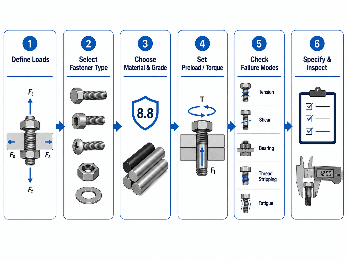
The most important takeaway is sequence: do not start with a bolt size. Start with what the joint must do, then choose hardware, preload, thread engagement, locking method, and inspection details that support that function.
What is Fastener Design?
Fastener design is the engineering work behind a reliable connection. It includes choosing the fastener type, diameter, length, thread form, grade, material, coating, washer, nut, tapped-hole depth, preload target, tightening method, locking method, and inspection requirement. A fastener can be a bolt, screw, stud, nut, washer, rivet, pin, threaded insert, or specialty locking component.
In a simple classroom problem, a bolt may be treated as a member that carries direct shear or tension. In a real bolted joint, the bolt is often intended to clamp parts together. That clamp force helps the joint resist separation, slip, fatigue, and vibration loosening. In other joints, the fastener may act more like a locating or bearing element, but fit, preload, and stiffness still affect performance.
A fastener should be selected as part of a load path. The bolt, washer, nut, tapped part, clamped materials, hole geometry, torque procedure, and service environment all affect whether the connection works.
Fastener Design Inputs and Outputs
A good fastener design process turns joint requirements into clear hardware and drawing decisions. The designer should know what loads the joint carries, what materials are being clamped, how the joint will be assembled, and what service conditions could change preload or strength over time.
| Design input | Examples | Output decision |
|---|---|---|
| Load case | Tension, shear, prying, moment, fatigue, vibration, impact, thermal load | Fastener size, quantity, spacing, preload target, and whether slip is allowed |
| Joint architecture | Through bolt, tapped hole, stud, insert, rivet, dowel-assisted joint | Hardware type, access requirements, serviceability, and thread engagement strategy |
| Clamped materials | Steel, aluminum, cast iron, plastic, composite, gasketed stackup, coated surfaces | Washer selection, bearing area, thread depth, insert use, and material compatibility |
| Assembly method | Hand torque, calibrated torque wrench, turn-of-nut, tensioning, production tool | Torque note, lubrication assumption, tightening sequence, and inspection method |
| Service environment | Outdoor exposure, washdown, salt spray, heat, vibration, repeated removal | Coating, corrosion allowance, locking method, replacement interval, and maintenance instruction |
How a Bolted Joint Carries Load
A bolted joint works by stretching the bolt and compressing the clamped parts. The stretched bolt creates preload, also called clamp force. When an external tensile load is applied, only part of that load may increase bolt tension if the clamped parts remain compressed. If the joint separates, the bolt can suddenly see much more direct load and fatigue risk increases.
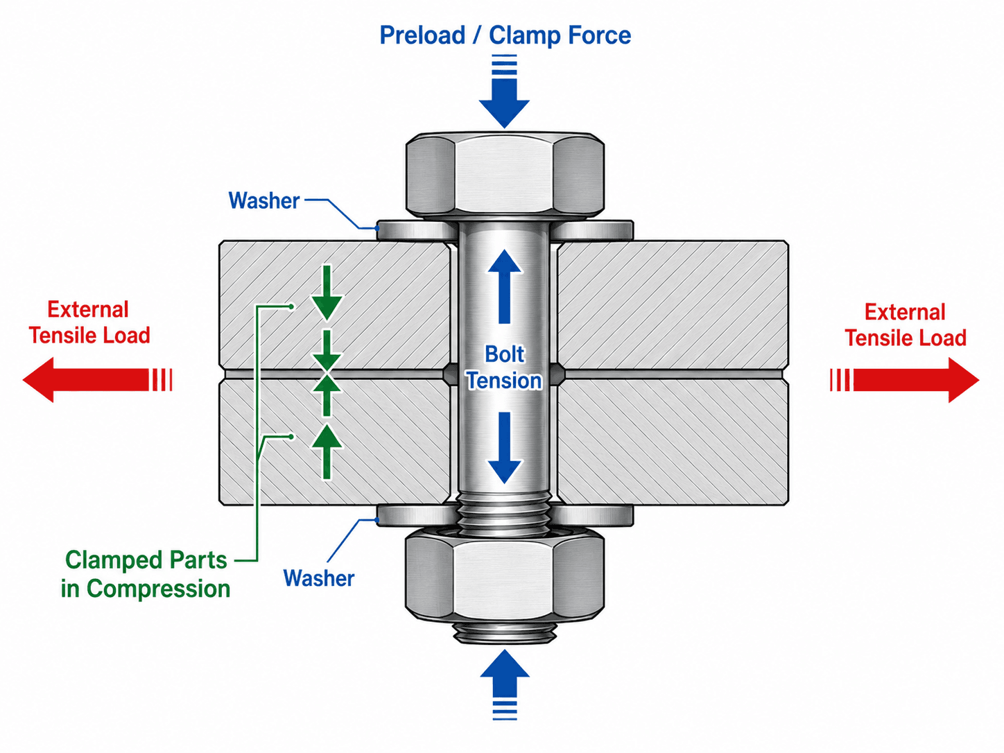
Preload and clamp force
Preload is the initial tensile force in the fastener after tightening. It is usually created by torque, turn-of-nut, tensioning, or another controlled assembly method. In many mechanical assemblies, proper preload is what keeps the parts from slipping, opening, fretting, or vibrating loose.
Friction, bearing, and direct shear
Some joints are intended to carry shear through friction between clamped parts. Others carry shear through bearing of the bolt shank against the hole. The difference matters because a friction-type joint depends strongly on clamp force and surface condition, while a bearing-type joint depends strongly on hole geometry, edge distance, bolt shank location, and plate bearing strength.
Threads in the load path
Threads are stress concentrators and have a smaller effective tensile area than the full shank diameter. When possible, high-shear joints are detailed so the smooth shank crosses the shear plane instead of the threaded portion. If threads must be in the shear plane, the reduced area and fatigue implications should be considered.
Choosing the Right Fastener Type
Fastener selection starts with the function of the joint. A removable equipment cover, a high-vibration machine frame, a tapped aluminum housing, and a permanent sheet-metal joint may all need different fastening strategies even if the load looks similar.
| Fastener or joint detail | Use this when | Avoid or review carefully when | Key design check |
|---|---|---|---|
| Through bolt with nut | Both sides are accessible and the joint must be serviceable. | Access is limited or protruding threads create clearance or safety issues. | Grip length, washer bearing, nut engagement, and tool access on both sides. |
| Cap screw into tapped hole | The back side is inaccessible or the assembly needs a clean blind-side installation. | The tapped material is weak, thin, cast, or frequently serviced. | Thread engagement, blind-hole depth, bottoming risk, and parent material strength. |
| Stud with nut | The joint is assembled often, operates hot, or needs reduced wear in the parent threads. | The stud can loosen during service or installation depth is hard to control. | Stud installation depth, exposed thread length, nut engagement, and replacement rules. |
| Threaded insert | The parent material is aluminum, plastic, composite, soft, or repair-prone. | The insert installation process is not controlled or pull-out strength is uncertain. | Insert pull-out, parent material strength, installation method, and service cycles. |
| Rivet or permanent fastener | The joint is permanent, thin-sheet, high-production, or not intended for field service. | Disassembly, retightening, or precise clamp control is required. | Hole quality, sheet bearing, pull-through, and inspection method. |
| Locking nut, patch, washer, or adhesive | The joint is exposed to vibration, repeated motion, or preload loss risk. | The locking feature is being used to compensate for poor preload or poor joint design. | Preload retention, temperature range, removal method, and reuse limitations. |
| Captive fastener | Loose hardware must be prevented during service, access panels, or field maintenance. | The captive feature reduces strength, clearance, or replacement flexibility. | Retention strength, service access, installation tolerance, and replacement method. |
If the assembly will be serviced often, prioritize repeatable installation and thread durability. If it will see vibration, prioritize preload retention, slip control, and fatigue resistance before choosing a locking product.
Fastener Design Factors That Control the Joint
Fastener design is controlled by load, geometry, material behavior, and assembly uncertainty. The same nominal bolt can behave very differently in a thick steel joint, a tapped aluminum housing, a thin sheet bracket, or a vibrating machine base.
| Design factor | Why it matters | Engineering implication |
|---|---|---|
| External tension | Can open the joint and increase bolt stress. | Check preload, joint separation, tensile stress area, prying action, and fatigue stress range. |
| External shear | Can be carried by friction, bearing, dowels, or the bolt shank depending on joint design. | Decide whether slip is allowed and whether the shank or threads cross the shear plane. |
| Preload target | Controls clamping, slip resistance, joint separation, and fatigue behavior. | Specify a realistic tightening method and account for torque-preload scatter. |
| Fastener grade and material | Determines proof strength, tensile strength, ductility, corrosion behavior, and temperature limits. | Do not upgrade strength without checking parent material, galling, coating, and embrittlement risk. |
| Thread engagement | Controls whether internal threads strip before the bolt reaches intended capacity. | Weak tapped materials may need deeper engagement, inserts, larger diameter, or a through bolt. |
| Washer and bearing area | Distributes load under the head or nut and protects softer surfaces. | Check washer hardness, embedment, pull-through, and whether the washer fits the hole and surface. |
| Multi-fastener load sharing | Bolts in a pattern rarely share load perfectly if the joint is flexible or tolerances vary. | Review bolt spacing, prying, eccentric load, hole clearance, and whether locating features are needed. |
| Vibration and cyclic loading | Can reduce preload, initiate fatigue cracks, and cause self-loosening. | Review clamp length, locking method, fatigue stress range, and inspection interval. |
| Corrosion and environment | Can reduce section, lock threads, change friction, or cause galvanic attack. | Match coatings and materials to the environment and avoid incompatible metal pairs where possible. |
Core Fastener Design Equations
Fastener design often uses simple equations for preliminary checks, then applies judgment for preload uncertainty, fatigue, joint stiffness, and standards-based requirements. These equations are useful for understanding the mechanics, but they should not be treated as a complete design method by themselves.
Torque and preload estimate
A common simplified nut-factor relationship estimates tightening torque from desired preload:
- \(T\) Tightening torque, commonly in N·m, lb·ft, or lb·in.
- \(K\) Nut factor or torque coefficient. It depends on friction, lubrication, coating, surface finish, and hardware condition.
- \(F_i\) Initial bolt preload or clamp force, commonly in N or lbf.
- \(d\) Nominal fastener diameter, commonly in mm or inches.
The equation is useful for estimating torque, but it hides the biggest practical problem: most applied torque is spent overcoming friction under the head and in the threads. Small changes in lubrication or coating can produce large changes in actual clamp force.
| Torque or assembly condition | Effect on preload | Design action |
|---|---|---|
| Lubricated threads or bearing surface | Usually produces more preload for the same torque than a dry condition. | Specify the lubricant or dry condition instead of listing torque alone. |
| Dry or dirty threads | Preload can be lower and less repeatable because friction is higher and inconsistent. | Control cleanliness, thread condition, and installation procedure. |
| Coated or plated hardware | Friction and preload can differ from plain steel hardware. | Confirm torque values are appropriate for the coating and supplier condition. |
| Reused fasteners | Threads, coatings, and bearing surfaces may no longer match the original torque assumption. | Define reuse limits or replacement requirements for critical joints. |
| Soft clamped material or gasketed stack | Embedment, creep, or relaxation can reduce clamp force after tightening. | Consider retorque procedure, washers, sleeves, inserts, or a different joint detail. |
Bolt tensile stress check
For axial bolt loading, tensile stress is commonly estimated using the tensile stress area:
Here, \(F_b\) is the tensile force in the bolt and \(A_t\) is the tensile stress area of the threaded section. This check helps determine whether the fastener is approaching proof, yield, or ultimate strength limits.
Direct shear check
For simple direct shear, a preliminary average shear stress estimate is:
Here, \(V\) is applied shear load, \(n\) is the number of effective shear planes or fasteners sharing the load, and \(A_s\) is the relevant shear area. The selected area should reflect whether the shear plane passes through the shank or through the threaded portion.
A calculated bolt stress may look acceptable while the joint is still poorly designed. Thread stripping, bearing, edge tear-out, joint separation, fatigue, preload loss, and assembly scatter can control before simple bolt stress does.
Thread Engagement and Tapped Hole Design
Thread engagement is the length over which external bolt threads engage internal threads in a nut, tapped hole, or insert. It matters because threaded joints can fail by stripping the internal threads, stripping the bolt threads, or damaging the parent material around the hole.
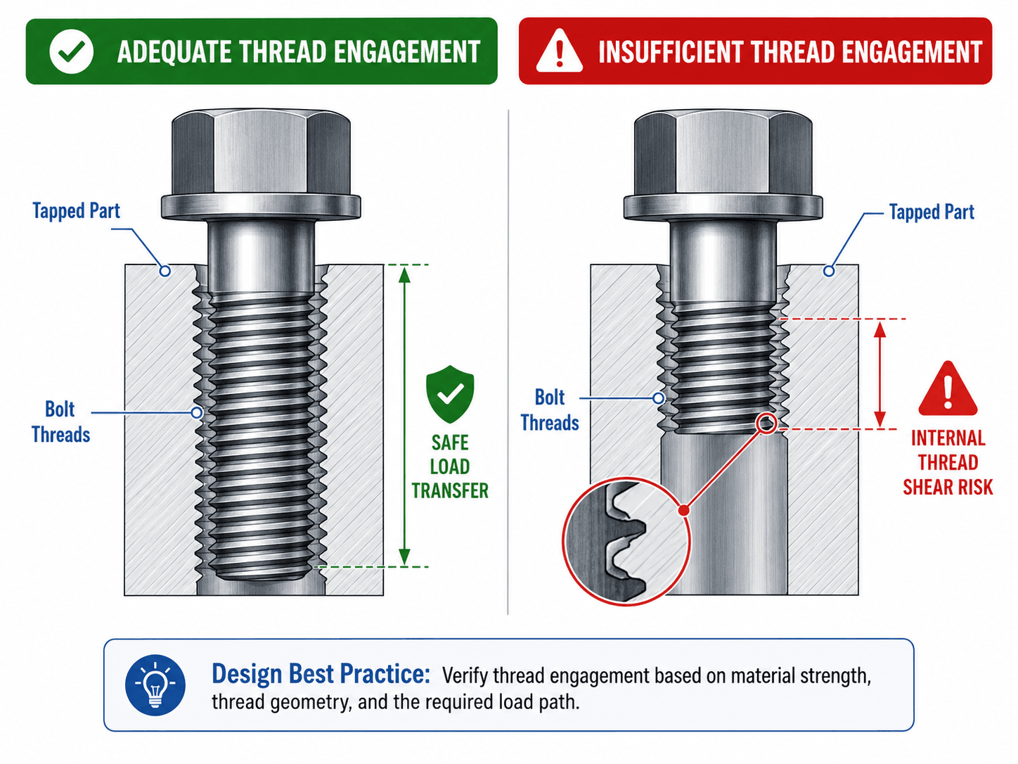
Thread engagement becomes especially important when a steel screw is installed into aluminum, magnesium, plastic, composite, cast material, or another weaker parent material. In those cases, the tapped part may fail before the fastener itself. A larger diameter, deeper engagement, insert, through bolt, or different joint architecture may be better than simply choosing a stronger screw.
What to check in a tapped hole
- Internal thread shear area in the tapped material.
- External thread strength of the fastener.
- Minimum full thread depth after chamfer, countersink, drill point, or blind-hole clearance.
- Parent material strength, casting quality, insert pull-out, and repeated service cycles.
- Whether the fastener can bottom out before it actually clamps the parts.
Avoid universal thread-depth rules without context. The correct engagement depends on bolt diameter, thread geometry, fastener strength, tapped material strength, load direction, and whether the joint will be repeatedly assembled.
Common Fastener Failure Modes
Fastener failures are not all bolt failures. Many real problems occur in the joint: stripped threads, crushed material, enlarged holes, lost preload, fretting, corrosion, fatigue cracking, or loose hardware. A good design review asks how the whole connection could fail.
| Failure mode | What it looks like | Practical design check |
|---|---|---|
| Bolt tensile overload | Fastener stretches, yields, or fractures under axial load. | Check tensile stress area, preload, external load share, prying action, and proof strength. |
| Bolt shear | Fastener shears across one or more planes. | Check whether shear occurs through the shank or threads and whether load sharing is realistic. |
| Thread stripping | Internal or external threads tear out before the bolt develops intended strength. | Check engagement length, material strength, thread form, and tapped-hole depth. |
| Bearing or hole elongation | Clamped material crushes around the hole or the hole becomes oval. | Check plate thickness, edge distance, washer use, and bearing stress. |
| Pull-through | Bolt head, nut, or washer pulls through a thin or soft part. | Increase bearing area, use proper washers, thicken the part, or change the joint layout. |
| Fatigue cracking | Crack initiates at thread roots, under the head, or at a stress concentration. | Reduce cyclic stress range, maintain preload, improve clamp length, and avoid bending in the fastener. |
| Self-loosening | Joint loses clamp force under vibration, slip, embedment, or repeated movement. | Review preload, joint slip, locking method, surface embedment, and inspection marking. |
| Corrosion or galling | Threads seize, pit, rust, or tear during tightening or removal. | Check material pairing, coating, lubrication, environment, and stainless-on-stainless galling risk. |
Why preload matters for fatigue
In a properly clamped joint, external cyclic load is shared between the bolt and the compressed joint members. That can reduce the alternating stress range in the bolt. If the joint separates, slips, or loses preload, the bolt can experience a much larger cyclic stress range, making thread roots, under-head fillets, and the first engaged thread more vulnerable to fatigue cracking.
Senior Engineer Fastener Design Review Checklist
A strong fastener review checks the drawing, analysis, service conditions, and assembly process together. This checklist is useful before releasing a mechanical design, prototype drawing, maintenance procedure, or production assembly.
Define the joint function first, then confirm the load path, then check fastener strength, thread engagement, parent material, preload method, locking method, corrosion exposure, tool access, and inspection requirements. If any item depends on friction or torque, document the assumption instead of leaving it implicit.
| Review check | What to look for | Why it matters |
|---|---|---|
| Joint function | Is the joint meant to clamp, locate, seal, carry shear, allow service, or stay permanent? | The function determines whether preload, bearing, dowels, inserts, or locking features are most important. |
| Load path | Identify tension, shear, moment, prying, fatigue, vibration, and thermal load effects. | Fasteners often fail because secondary loads were not considered in the layout. |
| Preload and torque | Check target clamp force, torque value, lubrication condition, coating, and tightening tool method. | Torque without a friction assumption is not a reliable clamp-force specification. |
| Thread engagement | Confirm full thread depth, parent material strength, insert details, and blind-hole clearance. | A tapped hole can strip even when the selected screw grade looks strong enough. |
| Shear plane location | Check whether the shear plane crosses the smooth shank or threaded portion. | Threads reduce effective area and increase stress concentration in shear and fatigue. |
| Washer and bearing surface | Confirm washer type, washer hardness, hole size, surface flatness, and contact area. | Soft or thin parts can embed, crush, or pull through under clamp load. |
| Material and coating compatibility | Review corrosion exposure, galvanic pairing, stainless galling, hydrogen embrittlement risk, and temperature. | Environment and surface treatment can control both strength and assembly behavior. |
| Multi-bolt pattern | Review eccentric load, spacing, hole tolerance, stiffness, and whether all bolts actually share load. | Real bolt groups can overload one fastener when prying, misalignment, or flexible plates are ignored. |
| Access and inspection | Confirm wrench clearance, assembly sequence, torque access, witness marks, and service replacement rules. | A good calculation is not useful if the joint cannot be assembled or inspected as specified. |
Fastener Design Example: A Bolted Bracket
Consider a small steel bracket bolted to a machine frame with two cap screws. The bracket carries a vertical shear load and may see vibration during operation. A weak design approach would simply pick two screws from a catalog based on estimated shear load. A better fastener design review asks how the load reaches the frame.
Step 1: Define the joint function
If the bracket must not slip, clamp force and surface condition matter. If small slip is acceptable and the screws bear against the holes, then bolt shear, hole bearing, and edge distance become more important. If the bracket also supports a moment, one screw may see higher tensile load than the other.
Step 2: Select the fastener and joint detail
A through bolt may be preferred when both sides are accessible and the bracket is serviceable. A tapped hole may be preferred when the back side is inaccessible, but then thread engagement in the frame becomes a critical design item. Washers may be needed to spread clamp load and protect the bracket surface.
Step 3: Interpret the result like an engineer
If bolt stress is acceptable but the tapped frame material is weak, the design may still need deeper engagement, a larger screw, an insert, or a through-bolt conversion. If vibration is expected, the review should also include preload retention, locking strategy, witness marking, and fatigue rather than only static strength.
Engineering Judgment and Field Reality
Real fastener performance depends heavily on manufacturing and assembly. Coatings change friction. Lubrication changes torque-preload behavior. Paint, burrs, rough surfaces, and soft gaskets can embed after tightening and reduce clamp force. Reused fasteners may not behave like new hardware. Stainless fasteners can gall. Blind holes can trap debris or bottom out. Tool access can prevent the specified torque method from being applied correctly.
The drawing should specify the condition the calculation assumes. A torque value without the fastener grade, lubricant or dry condition, washer detail, thread engagement, and tightening sequence can leave the most important parts of the design to chance.
In production environments, fastener design also needs to consider assembly time, mistake-proofing, tool clearance, operator variation, inspection method, replacement parts, and whether the joint can be reworked without damaging the parent material.
When This Breaks Down
Simplified fastener design breaks down when the joint behavior is controlled by preload uncertainty, fatigue, slip, temperature, corrosion, soft materials, or joint separation instead of simple static bolt strength.
- High-cycle vibration can make a statically strong fastener fail by fatigue or self-loosening.
- Soft clamped materials can creep, embed, crush, or relax, reducing clamp force after assembly.
- Blind tapped holes can strip, bottom out, or trap debris if usable thread depth is not checked.
- High-temperature joints can lose preload due to thermal expansion differences or material relaxation.
- Coatings, lubrication, plating, corrosion products, and thread damage can make torque-based preload estimates unreliable.
- Multi-bolt patterns may not share load evenly if the joint is flexible, prying occurs, or hole tolerances vary.
Common Fastener Design Mistakes and Practical Checks
Many fastener problems are caused by incomplete specifications rather than obviously undersized bolts. The most common mistakes happen when the designer checks one failure mode and assumes the rest of the joint will follow.
- Treating torque as guaranteed clamp force without accounting for lubrication, coating, and friction scatter.
- Choosing a stronger bolt without checking whether the tapped material, washer surface, or thin sheet can handle the load.
- Putting the threaded portion in the shear plane when the joint should use the smooth shank for shear transfer.
- Using short engagement in aluminum, plastic, or cast material and assuming the steel fastener strength controls.
- Ignoring prying action in brackets, flanges, and tabs where the geometry amplifies bolt tension.
- Forgetting tool clearance, tightening sequence, witness marks, or replacement rules on serviceable equipment.
The most dangerous fastener mistake is designing only the bolt and not the joint. A connection can fail by stripped threads, crushed parts, lost preload, vibration loosening, or fatigue even when the bolt’s catalog strength looks acceptable.
Engineering References and Design Guidance
Fastener design is often governed by project requirements, company standards, product requirements, industry practices, and detailed hardware specifications. A good reference helps designers understand materials, preload, torque, washers, locking methods, inserts, rivets, tapped holes, and practical installation concerns.
- NASA Fastener Design Manual: NASA Fastener Design Manual is a detailed engineering reference for fastener materials, finishes, torque, locking methods, washers, inserts, and related fastener design considerations.
- Project-specific criteria: Company standards, drawing notes, material specifications, equipment requirements, owner requirements, and inspection procedures may control final fastener selection and installation requirements.
- Engineering use: Use design references to support preload assumptions, material choices, locking methods, thread details, and review checks rather than relying only on catalog strength values.
Frequently Asked Questions
Fastener design is the process of selecting, sizing, and specifying bolts, screws, nuts, washers, threads, inserts, and locking features so a joint can safely carry load without loosening, stripping, yielding, corroding, or damaging the clamped parts.
No. Torque is the turning input applied during assembly, while preload is the clamp force created in the bolt. Friction under the head, in the threads, lubrication, coating, surface condition, and tool method can make the actual preload very different from the torque-based estimate.
A good fastener design checks bolt tension, bolt shear, combined stress, thread stripping, bearing, pull-through, edge tear-out, joint separation, fatigue, vibration loosening, corrosion, galling, and damage to the clamped parts.
Required thread engagement depends on bolt size, thread form, fastener strength, tapped material strength, loading, and safety factor. The goal is to provide enough internal thread shear area so the joint does not strip before the intended fastener strength is developed.
Bolts can loosen under vibration when relative slip, embedment, joint relaxation, or loss of preload allows movement in the joint. Correct preload, adequate clamp length, suitable locking features, and inspection marking help reduce loosening risk.
Summary and Next Steps
Fastener design is the mechanical design process of making a bolted, screwed, threaded, or otherwise fastened joint reliable. The fastener itself matters, but the real design problem is the full joint: load path, preload, material strength, thread engagement, bearing area, locking method, environment, and assembly control.
A strong design starts with the joint function, then checks the load case, fastener type, grade, torque or preload method, failure modes, tapped-hole details, washer bearing, vibration, corrosion, and inspection requirements. The best fastener designs are clear on the drawing and realistic in the field.
Where to go next
Continue your learning path with related Turn2Engineering resources.
-
Mechanical Design
Explore the broader mechanical design hub for component design, machine elements, and practical engineering workflows.
-
Engineering Calculators
Use engineering calculators for related strength, load, torque, and mechanical design calculations.
-
Engineering Equations
Review common engineering equations that support mechanical design analysis and design checks.