Key Takeaways
- Core idea: Power system efficiency compares useful delivered power with the power supplied after losses across lines, transformers, substations, feeders, and loads are considered.
- Engineering use: Engineers use efficiency studies to reduce energy losses, improve voltage profiles, evaluate equipment loading, and prioritize upgrades that save the most power for the least cost.
- What controls it: Current, conductor resistance, transformer loading, power factor, voltage level, phase balance, harmonics, and load profile strongly influence system losses.
- Practical check: Efficiency is not a fixed nameplate value; it changes with load, operating condition, voltage control, reactive power flow, and the system boundary being measured.
Table of Contents
Introduction
Power system efficiency is the percentage of supplied electrical power that reaches the intended load as useful power after losses are considered. In power systems engineering, efficiency is not just a generation issue; it depends on conductor heating, transformer losses, voltage level, reactive power flow, power factor, distribution layout, load balance, harmonics, and operating conditions.
Where Power Losses Occur in a Power System
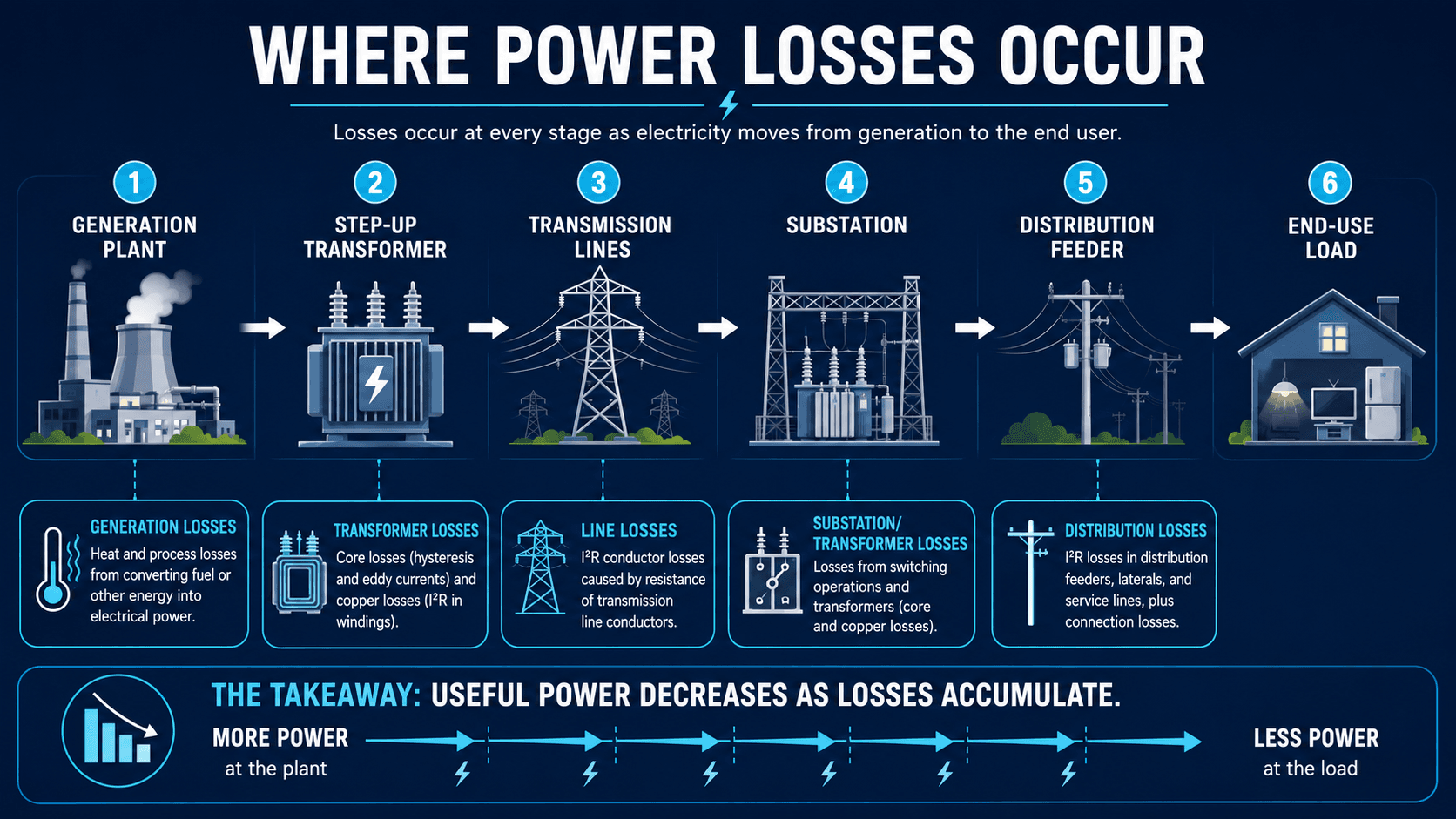
Read the diagram from left to right. The useful power available to the final load decreases as heat, transformer, conductor, switching, and distribution losses accumulate along the system.
What Is Power System Efficiency?
Power system efficiency describes how effectively an electrical power system transfers energy from a source to a useful load. At its simplest, it compares useful output power with input power. In real systems, the definition depends on the boundary being studied: a power plant, transformer, transmission corridor, distribution feeder, industrial facility, or complete grid.
In grid studies, power system efficiency often focuses on delivery losses after electricity is generated. Generation efficiency is a related but different concept that describes how effectively a plant converts fuel, solar, wind, hydro, or stored energy into electrical output before that power enters the delivery network.
A shallow definition might stop at “output divided by input,” but a real power system is made of many loss-producing elements. Conductors heat up as current flows, transformer cores consume magnetizing energy, reactive power increases current, poor load balance raises losses, and voltage drop affects the way loads and equipment operate. That is why engineers usually evaluate efficiency by segment, not as one universal number.
- \(\eta\) Efficiency, usually reported as a percentage.
- \(P_{\text{input}}\) Power entering the defined study boundary, such as generator output, feeder source power, or transformer input power.
- \(P_{\text{useful output}}\) Power delivered to the intended load or downstream system after losses inside the study boundary are removed.
Always define the boundary before calculating efficiency. A transformer efficiency calculation, a feeder loss calculation, and a grid-level transmission and distribution loss estimate are related, but they are not the same measurement.
Efficiency vs Losses vs Power Factor vs Voltage Regulation
Power system efficiency is closely related to losses, power factor, voltage regulation, and reliability, but these terms do not mean the same thing. A strong efficiency review separates the metric being measured from the operating condition that influences it.
| Concept | What it means | How it affects power system efficiency |
|---|---|---|
| Efficiency | The ratio of useful delivered power to input power across a defined boundary | It is the final performance metric used to compare delivered power against supplied power. |
| Losses | Power converted to heat, magnetizing energy, switching loss, metering error, or unaccounted energy | Higher losses reduce the useful power delivered to the load and lower system efficiency. |
| Power factor | The ratio of real power to apparent power in an AC system | Low power factor increases current for the same real power, which increases \(I^2R\) losses. |
| Voltage regulation | The ability to keep voltage within an acceptable range from source to load | Weak voltage regulation can increase current, worsen losses, and make equipment operate outside preferred conditions. |
| Reliability | The ability to deliver power continuously and within acceptable service quality limits | A system can be reliable but inefficient, or efficient under normal conditions but vulnerable during contingencies. |
The most common confusion is treating power factor as efficiency. Improving power factor can improve system efficiency by reducing current, but power factor itself is not the same as energy delivery efficiency.
Typical Power System Losses and What Good Efficiency Means
There is no single “good” efficiency number for every power system. A transformer, industrial service, distribution feeder, transmission corridor, and national grid all have different boundaries, equipment, voltage levels, load profiles, and loss mechanisms. A useful benchmark must match the type of system being studied.
At the utility level, transmission and distribution losses are commonly reported as a percentage of electricity transmitted and distributed. In the United States, the EIA reports that estimated annual transmission and distribution losses averaged about 5% from 2018 through 2022. That type of number is useful for grid-level context, but it should not be used as a universal target for every feeder, facility, or transformer.
| Study boundary | What “good efficiency” depends on | Engineering interpretation |
|---|---|---|
| Individual transformer | No-load core losses, load losses, transformer size, loading profile, and operating voltage | High nameplate efficiency may still perform poorly if the transformer is badly oversized or heavily overloaded. |
| Transmission corridor | Voltage level, line length, conductor resistance, power transfer, reactive compensation, and contingency loading | High-voltage operation reduces current, but long distances and reactive power flow still require careful loss review. |
| Distribution feeder | Lower voltage, radial length, conductor size, load density, phase balance, voltage regulation, and service transformers | Distribution losses can become significant because many feeder segments operate at lower voltage and higher current. |
| Industrial or commercial facility | Motors, drives, transformers, power factor, harmonics, load schedule, and internal distribution equipment | Efficiency improvements may come from power factor correction, motor upgrades, transformer review, load management, or harmonic mitigation. |
| Utility system | Technical losses, non-technical losses, metering accuracy, customer density, network age, voltage level, and data quality | System-level loss percentages combine many effects and should be interpreted with utility accounting methods in mind. |
A loss percentage is only meaningful when the measurement boundary, time interval, load condition, and included loss categories are clearly defined.
Main Types of Losses That Reduce Power System Efficiency
Power system losses are usually grouped into technical losses and non-technical losses. Technical losses are caused by normal electrical behavior in conductors, transformers, equipment, and loads. Non-technical losses come from metering errors, billing issues, unauthorized connections, data problems, or unaccounted energy.
| Loss type | Where it occurs | Why it matters for efficiency |
|---|---|---|
| Conductor \(I^2R\) losses | Transmission lines, distribution feeders, cables, buswork, and service conductors | Losses rise with the square of current, so overloaded or low-voltage circuits can lose significantly more energy as heat. |
| Transformer no-load losses | Transformer cores energized even when load is light | Core losses can remain present whenever the transformer is energized, making transformer selection important for lightly loaded systems. |
| Transformer load losses | Transformer windings under load | Copper losses increase with load current and can become important during peak loading or poor power factor operation. |
| Reactive power losses | Feeders, transformers, motors, inductive loads, and long lines | Reactive power does not perform real work at the load, but it increases current and can raise losses and voltage drop. |
| Harmonic losses | Systems with variable frequency drives, rectifiers, nonlinear electronics, and distorted current waveforms | Harmonics can increase RMS current, transformer stray losses, conductor heating, and neutral loading beyond what a simple sinusoidal model suggests. |
| Phase imbalance losses | Three-phase feeders, panels, transformers, and multi-phase distribution networks | Unbalanced phase currents increase losses, neutral current, voltage imbalance, and equipment stress. |
| Non-technical losses | Metering, billing, data collection, and energy accounting systems | These losses do not come from circuit physics, but they affect utility-level efficiency reporting and loss-reduction programs. |
The most common physical relationship behind conductor and winding losses is simple but powerful: current matters more than many readers expect. If current doubles through the same resistance, resistive loss increases by four times.
Why Voltage, Current, and Power Factor Control Efficiency
For a given real power demand, a system can reduce current by operating at a higher voltage or by improving power factor. Lower current reduces heating losses in conductors and transformer windings. This is the engineering reason that bulk power is transmitted at high voltage and why poor power factor can make a system less efficient even if the real load has not changed.
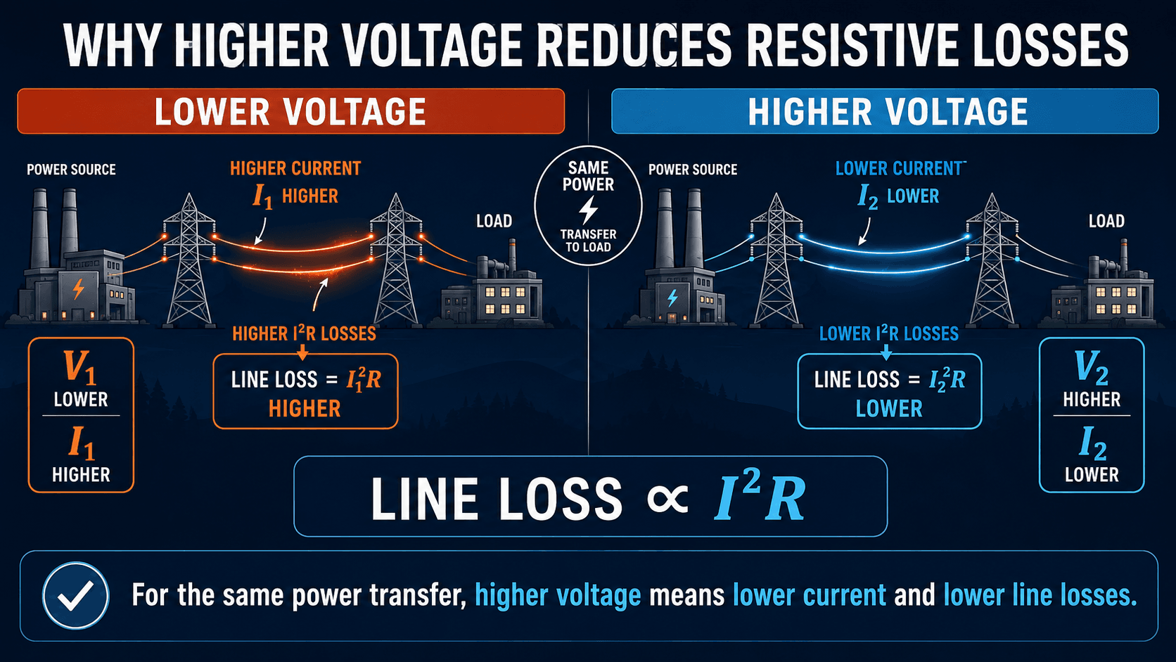
Resistive losses increase with current squared
The relationship \(P_{\text{loss}} = I^2R\) is one of the most important efficiency concepts in power systems. The resistance of a conductor may look small, but long distances, high load current, high conductor temperature, and peak loading can make the energy loss meaningful.
Worked example: why current reduction matters
Assume a circuit has the same conductor resistance in both cases. If current is reduced from 200 A to 100 A, the loss ratio becomes:
The new resistive loss is 25% of the original loss, which means the loss is reduced by 75%. This is why reducing current through higher voltage, better power factor, load balancing, or conductor upgrades can have a large efficiency impact.
Power factor changes current for the same real power
In AC systems, loads may require both real power and reactive power. Low power factor means more current is needed to deliver the same real power. That extra current uses feeder and transformer capacity, increases losses, and can worsen voltage drop.
This form assumes a balanced three-phase AC system using line-to-line voltage. Single-phase systems, unbalanced circuits, and distorted waveforms require different handling. For balanced three-phase systems, the equation shows why current rises when power factor decreases for the same real power and line-to-line voltage.
Transmission Efficiency vs Distribution Efficiency
Transmission and distribution losses are often discussed together, but they behave differently. Transmission systems move bulk power over long distances at high voltage, while distribution systems deliver power locally at lower voltages through feeders, laterals, service transformers, and service conductors. Distribution circuits may be shorter, but their lower voltage and higher current can make local losses significant.
| System segment | Typical efficiency issue | Engineering implication |
|---|---|---|
| High-voltage transmission | Long line length, reactive power flow, conductor heating, corona on some high-voltage lines, and contingency loading | Engineers review voltage level, conductor size, line loading, reactive compensation, and transfer limits. |
| Subtransmission | Intermediate voltage networks can carry large regional loads with mixed transmission and distribution behavior | Loss studies often require load flow cases across peak, light-load, and contingency conditions. |
| Distribution feeders | Lower voltage, high current, long radial feeders, voltage drop, phase imbalance, and many connected transformers | Efficiency improvements may involve feeder reconfiguration, conductor upgrades, capacitor placement, voltage regulation, and load balancing. |
| End-use facilities | Motors, drives, transformers, lighting, process loads, harmonics, and poor power factor | Facility-level efficiency often depends on power factor correction, motor efficiency, load scheduling, and power quality review. |
A useful efficiency study separates these segments instead of treating the entire grid as one black box. The best improvement may be a transmission upgrade in one case, but a transformer change, capacitor bank, or feeder balancing project in another.
How Engineers Improve Power System Efficiency
Efficiency improvement is usually a practical tradeoff between loss reduction, reliability, cost, constructability, equipment life, and system flexibility. The right solution depends on whether the dominant losses are caused by current, resistance, transformer loading, reactive power, unbalanced phases, harmonics, or poor system monitoring.
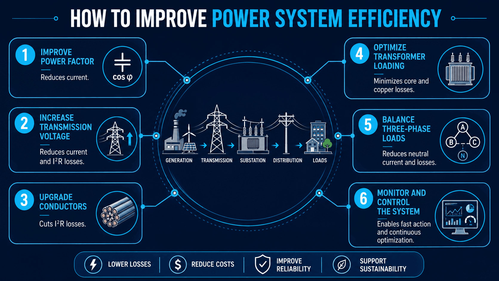
| Improvement method | What it targets | Practical tradeoff |
|---|---|---|
| Improve power factor | Reduces unnecessary current caused by reactive power demand | Capacitor banks or inverter VAR controls must be coordinated so they do not create overvoltage, resonance, or switching issues. |
| Increase voltage where appropriate | Reduces current for the same power transfer | Higher voltage may require insulation, equipment, clearances, protection, and capital upgrades. |
| Upgrade conductors | Reduces circuit resistance and heating losses | Material, route, structure loading, outage scheduling, and installation cost must be justified by loss savings and capacity needs. |
| Optimize transformer loading | Balances no-load losses and load losses | An oversized transformer may waste energy at light load, while an overloaded transformer may run hot and inefficiently. |
| Balance three-phase loads | Reduces phase current imbalance and neutral current | Load balancing may require field switching, panel review, feeder reconfiguration, or service-level data. |
| Monitor and control the system | Finds high-loss operating conditions quickly | Good metering, SCADA, AMI, power quality data, and model validation are needed before optimization decisions are trusted. |
How Power System Efficiency Is Evaluated
A simple efficiency equation is helpful for learning, but engineering studies usually evaluate losses through measurements, load flow models, equipment data, and operating scenarios. The goal is not only to calculate a percentage; it is to find where losses occur, whether they are avoidable, and whether an upgrade is economically justified.
Simple boundary calculation
For a defined segment, efficiency can be calculated if input power and useful output power are known over the same condition or time interval. For example, if a feeder receives 10.0 MW at the source and delivers 9.55 MW to connected loads, the feeder efficiency for that operating point is:
That result also implies 0.45 MW of losses inside the feeder boundary at that loading condition. The number is useful only if the source measurement, load measurement, and study boundary are consistent.
Load flow analysis
In larger networks, engineers use load flow analysis to calculate bus voltages, real and reactive power flows, transformer loading, line loading, voltage drop, and system losses. A load flow model can compare alternatives such as capacitor placement, conductor upgrades, transformer tap changes, feeder reconfiguration, and distributed energy resource controls.
Measurement-based loss review
Utilities and facilities also compare metered energy entering and leaving system boundaries. This helps separate technical losses from non-technical losses, but the result depends on meter accuracy, time synchronization, customer data, transformer records, and unmetered loads.
Power System Efficiency Review Checklist
Use this checklist to move from a general efficiency concern to a targeted engineering review. The goal is to identify whether losses are mainly driven by current, resistance, transformer operation, reactive power, voltage profile, load balance, harmonics, or metering uncertainty.
Start with the measurement boundary, confirm load and source data, identify the largest loss segment, then test improvements in a load flow model or measured operating case before recommending equipment changes.
| Efficiency check | What to look for | Why it matters |
|---|---|---|
| Define the boundary | Generator bus, transformer, feeder, facility service, or full T&D system | Efficiency is meaningless unless input power and delivered power are measured across the same boundary. |
| Review peak and average loading | Peak current, load factor, seasonal demand, and time-of-day profiles | \(I^2R\) losses can be dominated by peak periods even if average loading appears moderate. |
| Check voltage profile | Source voltage, midpoint voltage, end-of-line voltage, regulator operation, and transformer tap positions | Poor voltage control can increase current, worsen losses, and create equipment operating problems. |
| Check power factor | Low power factor at major loads, feeders, substations, or the utility service point | Low power factor increases current and can raise conductor and transformer losses. |
| Review transformer loading | Lightly loaded, heavily loaded, oversized, or overloaded transformers | Transformer efficiency depends on both no-load core losses and load-dependent copper losses. |
| Evaluate conductor resistance | Conductor size, length, material, operating temperature, and feeder configuration | Higher resistance directly increases heating losses for a given current. |
| Check phase balance | Phase currents, neutral current, single-phase load concentration, and feeder switching | Imbalance increases losses and can create voltage imbalance and equipment stress. |
| Review harmonics and power quality | Total harmonic distortion, nonlinear load concentration, neutral heating, and transformer temperature | Distorted currents can increase losses beyond what a simple fundamental-frequency calculation suggests. |
| Validate metering and data | Meter accuracy, timestamps, missing accounts, unmetered loads, and data gaps | Bad data can make a technical loss problem look larger or smaller than it really is. |
Engineering Judgment and Field Reality
The most efficient technical option is not always the best project option. A conductor upgrade may reduce losses, but it may also require outages, structural review, permitting, protection changes, and capital expense. A capacitor bank may improve power factor, but it must be coordinated with voltage limits, switching transients, harmonics, and system operating modes.
Experienced engineers look for the highest-value loss reduction, not theoretical perfection. A feeder with high peak losses may justify targeted improvements, while a lightly loaded circuit may not produce enough energy savings to justify a major rebuild. Efficiency analysis should be tied to reliability, safety, maintainability, and life-cycle cost.
A power system can be efficient under one operating case and inefficient under another. Always compare peak load, light load, seasonal operation, contingency cases, and future load growth before deciding which improvement is truly justified.
When This Breaks Down
Simplified efficiency calculations break down when the system boundary is unclear, the load is changing rapidly, the power factor varies, the voltage profile is not measured, or the system contains nonlinear loads. In those cases, a single percentage can hide the real source of losses.
- Changing load conditions: A one-time efficiency calculation may not represent annual losses if the system has strong daily or seasonal load swings.
- Reactive power movement: Real power efficiency can look acceptable while reactive power flow still causes unnecessary current, voltage drop, and equipment loading.
- Nonlinear loads: Harmonics from drives, rectifiers, and power electronics can increase RMS current, transformer stray losses, conductor heating, and neutral current, especially where triplen harmonics from nonlinear single-phase loads are present.
- Unverified models: Load flow results can mislead if conductor data, transformer taps, load allocation, regulator settings, or capacitor status are wrong.
- Mixed technical and non-technical losses: Metering and billing losses should not be treated as conductor or transformer losses without evidence.
Common Mistakes and Practical Checks
Power system efficiency is often misunderstood because the basic formula looks simple. The challenge is not writing the equation; the challenge is applying it to a real electrical network with changing load, voltage, power factor, equipment limits, and measurement uncertainty.
| Common mistake | Why it causes problems | Better engineering check |
|---|---|---|
| Treating efficiency as a fixed system value | Losses change with load current, voltage, transformer loading, and operating configuration. | Evaluate multiple operating cases, including peak load, light load, seasonal load, and expected future load. |
| Ignoring power factor | Low power factor increases current even when real power demand is unchanged. | Review real power, reactive power, apparent power, and power factor together. |
| Only reviewing transmission losses | Distribution feeders, service transformers, and local conductors can be major contributors to losses. | Separate transmission, subtransmission, distribution, and facility-level losses where possible. |
| Assuming every loss reduction project is economical | Some upgrades reduce losses but cost more than the value of the saved energy. | Compare annual loss savings, capacity benefits, reliability improvements, outage costs, and capital cost. |
| Using model results without data validation | Bad conductor lengths, transformer data, load allocation, or capacitor status can distort loss estimates. | Calibrate the model against metering, SCADA, field records, and known operating conditions. |
Do not use a single efficiency percentage to diagnose an entire system. Break the system into segments, identify the dominant loss mechanism, and verify whether the proposed fix addresses that mechanism directly.
Useful References and Design Context
Transmission and distribution loss data are often used to understand grid-level efficiency, benchmark loss trends, and separate delivered electricity from energy lost inside the delivery network. For a public technical reference on how these losses are reported, the U.S. Energy Information Administration provides a useful explanation of electricity transmission and distribution loss calculations.
- U.S. Energy Information Administration: EIA explanation of electricity transmission and distribution losses describes how estimated T&D losses are calculated as a percentage and why direct-use electricity is treated separately from electricity placed onto the grid.
- Project-specific criteria: Utility planning standards, owner requirements, interconnection studies, equipment ratings, and protection requirements may control which efficiency improvements are acceptable.
- Engineering use: Engineers combine public data, metering, equipment records, and power system models to identify whether losses are normal, avoidable, or a sign of a design or operating issue.
Frequently Asked Questions
Power system efficiency is the percentage of supplied electrical power that reaches the intended load as useful power after losses in generation, transformers, transmission lines, substations, distribution feeders, and connected equipment are considered.
The basic formula is efficiency equals useful output power divided by input power, multiplied by 100 percent. In a grid or feeder study, engineers must define the measurement boundary carefully so input power, delivered power, and losses are compared over the same operating condition.
For the same real power transfer, higher voltage allows lower current. Because resistive line losses are proportional to current squared, reducing current can significantly reduce heating losses in conductors, transformers, and other current-carrying equipment.
Poor power factor increases current for a given amount of real power. Higher current increases I²R losses, uses more equipment capacity, worsens voltage drop, and can make feeders, transformers, and cables operate less efficiently.
The largest losses depend on the system boundary, but common contributors include conductor I²R losses, transformer no-load and load losses, reactive power flow, poor power factor, unbalanced phases, harmonics, and distribution feeder losses. In utility studies, non-technical losses such as metering and billing issues may also be included.
Summary and Next Steps
Power system efficiency measures how much useful electrical power is delivered compared with the power supplied across a defined system boundary. It is affected by resistive conductor losses, transformer losses, reactive power, voltage level, power factor, load balance, harmonics, metering quality, and operating condition.
The practical workflow is to define the boundary, identify the dominant loss mechanism, review voltage and current behavior, validate the data, and compare improvement options against cost, reliability, and operating constraints. The best efficiency improvement is the one that reduces real losses without creating new voltage, protection, maintenance, or economic problems.
Where to go next
Continue your learning path with related Turn2Engineering resources.
-
Introduction to Power Engineering
Start with the broader generation, transmission, distribution, and utilization concepts that frame power system efficiency.
-
Load Flow Analysis
Learn how bus voltages, real and reactive power flows, transformer loading, and losses are calculated in steady-state power system studies.
-
Voltage Regulation
Review how voltage profiles are controlled and why voltage regulation is closely tied to current, losses, and equipment operation.