
Key Takeaways
- Core idea: Basic electronic components are the building blocks that let circuits control current, store energy, switch signals, emit light, and process information.
- Engineering use: Engineers use these parts to build power supplies, sensor circuits, control circuits, communication devices, embedded systems, and electronic products.
- What controls it: The important details are component value, rating, polarity, package, tolerance, temperature behavior, and how the part is connected in the circuit.
- Practical check: Many beginner circuit failures come from reversed polarity, missing current limiting, wrong transistor pinouts, or confusing a schematic symbol with the physical part.
Table of Contents
Introduction
Basic electronic components are the individual parts used to build electronic circuits, including resistors, capacitors, inductors, diodes, LEDs, transistors, integrated circuits, switches, and power sources. Each component has a specific job, such as limiting current, storing energy, controlling current direction, switching signals, producing light, or processing electrical information.
Basic Electronic Components Function Map
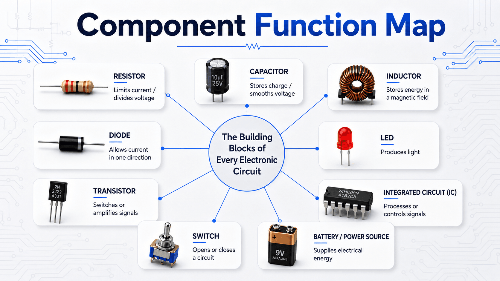
Start by reading the function first, not the part name. A circuit makes more sense when each component is tied to its job in the electrical path.
What Are Basic Electronic Components?
Basic electronic components are the physical and schematic building blocks used to create circuits. A resistor may limit current, a capacitor may smooth a voltage, a diode may force current in one direction, and a transistor may let a small signal control a larger current.
The important engineering idea is that components are not just isolated parts. Each one changes the relationship between voltage, current, energy, timing, or signal behavior. Beginners often memorize component names first, but real circuit understanding comes from asking what the part is controlling, storing, switching, protecting, or measuring.
| Component | Main job | Typical type | Polarity concern? |
|---|---|---|---|
| Resistor | Limits current or creates voltage drops | Passive | No |
| Capacitor | Stores charge, filters signals, smooths voltage | Passive | Sometimes |
| Inductor | Stores energy in a magnetic field | Passive | Usually no |
| Diode | Allows current primarily in one direction | Semiconductor | Yes |
| LED | Emits light when forward biased | Semiconductor output | Yes |
| Transistor | Switches or amplifies current | Active semiconductor | Pinout matters |
| Integrated circuit | Performs complex electrical functions | Active semiconductor | Orientation matters |
| Switch | Opens or closes a circuit path | Electromechanical | No for simple switches |
| Battery or power supply | Provides voltage and electrical energy | Source | Yes |
Physical Components vs Circuit Symbols
A physical part shows what the component looks like in a kit, on a breadboard, or on a circuit board. A circuit symbol shows how that part is represented in a schematic. The symbol is not meant to look exactly like the real part; it is meant to show electrical function and connection points.
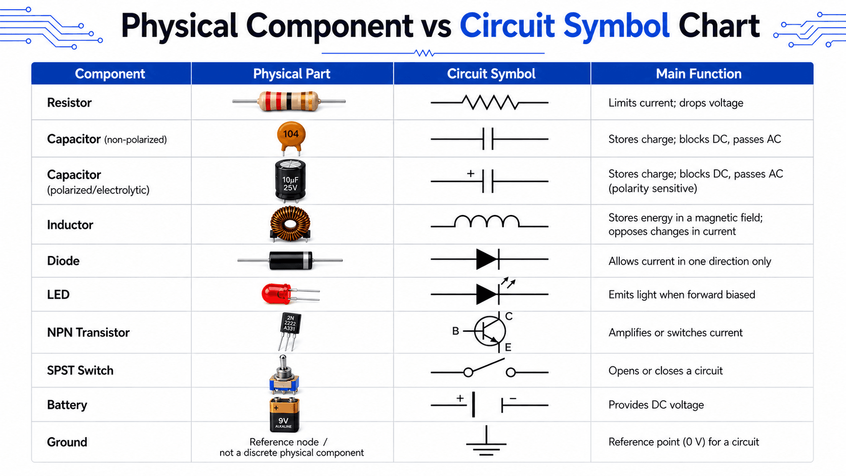
This distinction matters because troubleshooting usually happens across both views. A technician may inspect the physical board, while an engineer reviews the schematic. The same component must be understood in both contexts.
Passive, Active, and Electromechanical Components
One of the most useful ways to organize electronic components is by how they behave in a circuit. Passive components shape or store energy. Active components control current or voltage using an external power source. Electromechanical components use physical movement to make or break electrical connections.
| Category | Common components | How they behave | Beginner note |
|---|---|---|---|
| Passive components | Resistor, capacitor, inductor | Resist, store, filter, or release energy without signal gain | Values and ratings usually control whether the circuit behaves correctly. |
| Active components | Transistor, integrated circuit, op amp, voltage regulator | Control current or voltage and usually require a power supply | Pin orientation, operating voltage, and current limits are critical. |
| Electromechanical components | Switch, relay, connector, terminal block | Create, break, or route physical electrical connections | Contact rating and mechanical durability matter in real circuits. |
| Sources and references | Battery, power supply, ground node | Provide energy or define the circuit reference point | Ground is not automatically earth ground; it is often the 0 V reference. |
What the Main Basic Electronic Components Do
Each basic component can be understood by its circuit role. The goal is not just to name the part, but to understand what changes when that part is added, removed, reversed, oversized, undersized, or connected incorrectly.
Resistors
A resistor opposes current flow and creates a voltage drop. Resistors are used for LED current limiting, voltage dividers, pull-up and pull-down networks, timing circuits, and biasing transistors. The key ratings are resistance in ohms, tolerance, and power rating.
Ohm’s Law connects voltage \(V\), current \(I\), and resistance \(R\). If a resistor is too small, current may be excessive. If it is too large, the circuit may not deliver enough current to the next component.
Capacitors
A capacitor stores electric charge and resists sudden changes in voltage. Capacitors are used for filtering, timing, decoupling, smoothing power rails, and coupling AC signals between circuit stages. Ceramic capacitors are commonly non-polarized, while electrolytic capacitors are commonly polarized.
Inductors
An inductor stores energy in a magnetic field and resists sudden changes in current. Inductors are common in filters, switching power supplies, motor circuits, and radio-frequency circuits. Their behavior is strongly affected by current rating, core material, saturation, and frequency.
Diodes and LEDs
A diode allows current primarily in one direction. A light-emitting diode, or LED, is a diode that produces light when forward biased. Both are polarity-sensitive. Diodes are used for rectification, protection, signal steering, and clamping, while LEDs are used as indicators, displays, and light sources.
LED current-limiting resistor
A basic LED circuit usually needs a series resistor. If the supply voltage, LED forward voltage, and target current are known:
Example: choose an LED resistor
A \(5\ \text{V}\) supply powers an LED with a forward voltage of \(2.0\ \text{V}\). For a target current of \(10\ \text{mA}\):
A nearby standard resistor value such as \(330\ \Omega\) would reduce current slightly and is often a reasonable conservative choice for a simple indicator circuit.
Transistors
A transistor lets one electrical signal control another. In beginner circuits, transistors are often used as electronic switches for LEDs, motors, buzzers, relays, and logic signals. In analog circuits, transistors can also amplify signals. Pinout is a major practical issue because two similar-looking transistors can have different lead orders.
Integrated Circuits
An integrated circuit, or IC, contains many internal components inside one package. Common examples include logic gates, timers, op amps, microcontrollers, memory chips, and voltage regulators. IC orientation matters because pin 1 must match the schematic, PCB footprint, or breadboard wiring.
Other Common Electronic Components Beginners Should Know
Resistors, capacitors, inductors, diodes, transistors, and ICs form the core foundation, but real circuits commonly include several additional parts.
| Component | Main function | Important selection detail |
|---|---|---|
| Potentiometer | Adjustable resistance or voltage division | Total resistance, taper, and power rating |
| Relay | Electrically controlled mechanical switching | Coil voltage and contact current/voltage rating |
| Fuse | Overcurrent protection | Current rating, voltage rating, and time characteristic |
| Crystal / resonator | Provides a stable timing or frequency reference | Frequency, load capacitance, and tolerance |
| Connector | Creates removable electrical connections | Pin count, pitch, current rating, and keying |
| Sensor | Converts a physical quantity into an electrical signal | Supply, output type, range, accuracy, and interface |
How a Simple LED Circuit Uses Basic Components
A simple LED circuit is one of the clearest ways to see how basic electronic components work together. The battery provides voltage, the switch controls whether the circuit is open or closed, the resistor limits current, and the LED converts electrical energy into light.
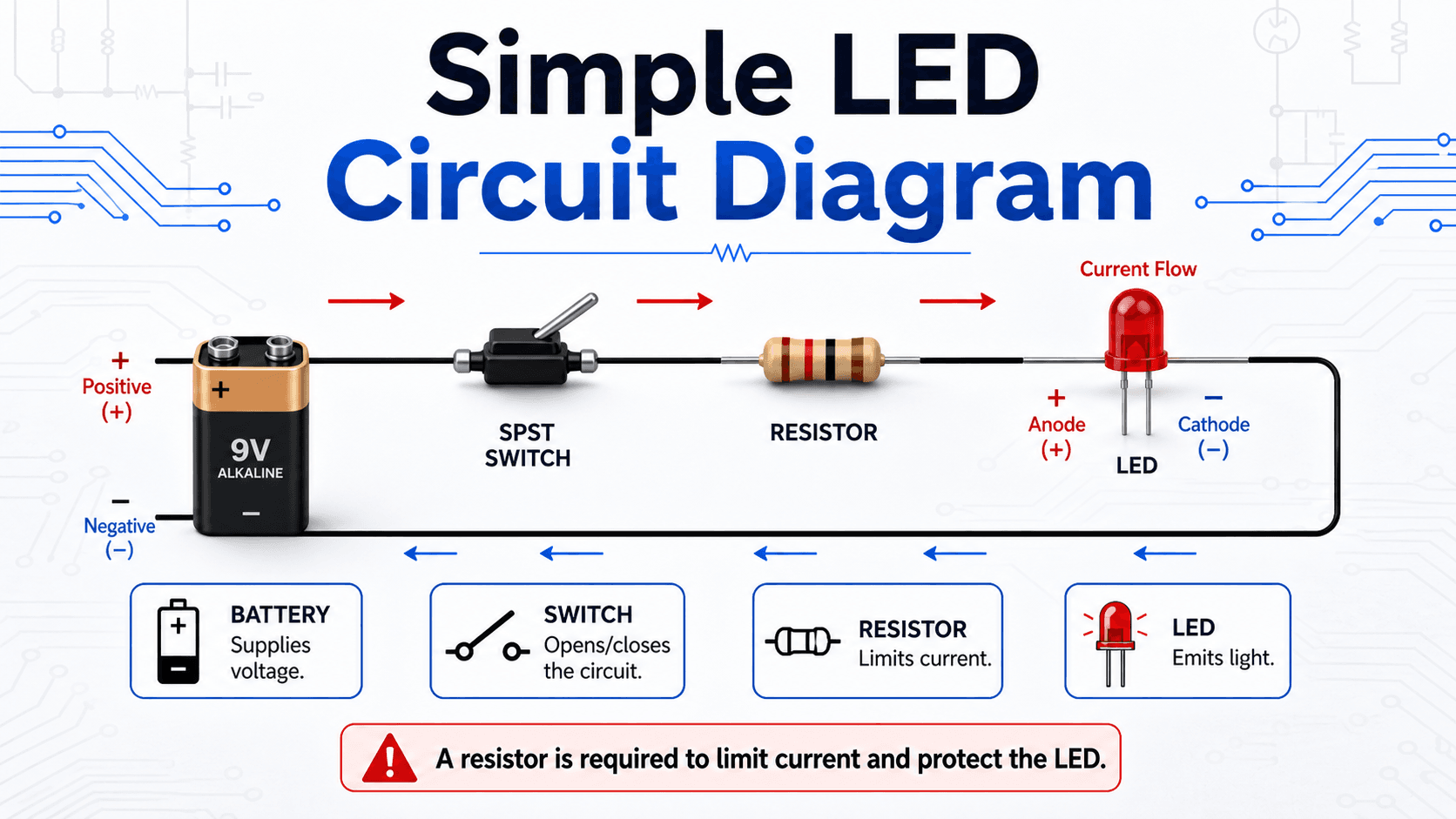
This diagram uses conventional current flow, which is normally shown from the positive terminal toward the negative terminal. Electron flow is physically opposite, but conventional current is the standard direction used in most circuit analysis and schematic explanation.
An LED should not be connected directly across a battery without current limiting. Once forward biased, LED current can increase quickly and damage the LED or the power source.
How to Read an Electronic Component Datasheet
A schematic tells you how a part connects; the datasheet tells you whether the actual device can survive and perform in that circuit. Even beginner designs benefit from checking a few core specifications.
- 1 Absolute maximum ratings: limits that should not be treated as normal operating targets.
- 2 Recommended operating conditions: the intended voltage, current, and temperature ranges.
- 3 Pinout: confirms lead or pin function and package orientation.
- 4 Electrical characteristics: typical and guaranteed performance values under stated conditions.
- 5 Package / footprint: confirms the physical device matches the PCB or prototype layout.
“Absolute maximum” does not mean “safe continuous operating point.” Good designs normally include margin below device limits.
Key Ratings and Details That Control Component Selection
Choosing the right component is not only about picking the right symbol. Engineers also check electrical rating, physical package, tolerance, operating environment, and how the part behaves outside ideal textbook conditions.
| Factor | Why it matters | Engineering implication |
|---|---|---|
| Value | Resistance, capacitance, inductance, forward voltage, or gain determines circuit behavior. | A wrong value can change timing, current, voltage division, filtering, or switching behavior. |
| Voltage rating | Components can fail if the applied voltage exceeds their rating. | Capacitors, diodes, transistors, and ICs need adequate voltage margin. |
| Current rating | Conductors, switches, diodes, transistors, and inductors heat up when current is excessive. | Underrated components may overheat, drift, fail, or become a safety concern. |
| Power rating | Resistors and semiconductors dissipate heat. | Power dissipation must be checked, especially for current-limiting resistors and switching devices. |
| Polarity and pinout | Many components only work correctly in one orientation. | Reversed LEDs, electrolytic capacitors, diodes, ICs, and transistors are common failure points. |
| Package and footprint | The physical part must fit the breadboard, PCB, enclosure, or connector system. | Through-hole parts are beginner-friendly; surface-mount parts are compact but harder to prototype by hand. |
Beginner Component Review Checklist
Use this checklist when looking at a schematic, breadboard, or beginner electronics kit. It helps connect the physical part, schematic symbol, circuit function, and practical failure points.
Identify the component symbol first, locate the matching physical part, check whether it has polarity or a required pin orientation, confirm its rating, then ask what job it performs in the circuit: current limiting, energy storage, switching, protection, signal processing, power supply, or return path.
| Check or decision | What to look for | Why it matters |
|---|---|---|
| Does the part have polarity? | Look for LED lead length, diode stripe, capacitor polarity mark, IC notch, or pin 1 dot. | Reversed polarity can stop the circuit from working or permanently damage the component. |
| Is current limited? | Check for a series resistor with LEDs or base/gate protection where needed. | Uncontrolled current is one of the fastest ways to damage beginner circuits. |
| Is the rating adequate? | Compare voltage, current, and power ratings against expected circuit conditions. | A component can be electrically correct but still fail if underrated. |
| Does the physical part match the schematic? | Compare symbol, pin count, package, and labels. | Wrong footprints, swapped transistor pins, and mirrored IC orientation cause common assembly errors. |
| Is there a complete return path? | Trace the path from source, through the load, and back to the source reference. | A circuit cannot operate just because the positive side is connected; current needs a closed path. |
How to Check Basic Components with a Multimeter
A digital multimeter can verify many basic circuit conditions before more advanced test equipment is needed.
| Check | Typical meter mode | What it can tell you |
|---|---|---|
| Resistor | Resistance | Whether measured resistance is near the expected value |
| Diode / LED | Diode test | Forward conduction, polarity, and possible open/short failure |
| Switch / fuse / wire | Continuity | Whether a low-resistance path is present |
| Supply rail | DC voltage | Whether the circuit is receiving the expected voltage |
Never use resistance or continuity mode on an energized circuit. Discharge capacitors and follow the meter and equipment safety requirements before testing.
How to Identify Components on a Circuit Board
Physical identification is a practical skill because real components are often smaller, differently shaped, or less obvious than the clean symbols shown in a schematic. On a printed circuit board, part labels, package shape, markings, polarity indicators, and nearby circuit context all help identify the component.
Start with package shape and markings
Resistors may use color bands or printed surface-mount codes. Capacitors may appear as small ceramic discs, rectangular surface-mount parts, or cylindrical electrolytic cans. Diodes often have a stripe marking the cathode. ICs usually have a notch, dot, or chamfer that identifies pin 1.
Use circuit context
A part near a power input may be a protection diode, fuse, regulator, capacitor, or connector. A resistor beside an LED is probably current limiting. A transistor near a motor, relay, or high-current load may be acting as a switch. Context often confirms what the physical marking alone does not.
ESD and Safe Component Handling
Many semiconductor devices can be damaged by electrostatic discharge even when the discharge is too small to feel. This matters especially for MOSFETs, CMOS ICs, sensors, and high-impedance inputs.
- Handle sensitive devices by the package rather than touching pins unnecessarily.
- Use appropriate ESD controls when working with static-sensitive components.
- Keep power removed while inserting or rewiring components unless the procedure specifically requires energized testing.
- Verify polarity and IC orientation before applying power.
Engineering Judgment and Field Reality
Introductory diagrams are intentionally simplified. Real circuits include tolerances, heat, supply variation, parasitic capacitance, inductance, noise, contact resistance, manufacturing variation, and component aging. These effects may not matter in a classroom LED circuit, but they become important in power electronics, sensors, communication circuits, and high-reliability designs.
A component can have the correct value and still be the wrong choice if its voltage rating, current rating, package, tolerance, thermal behavior, or environmental rating does not fit the actual circuit conditions.
When the Ideal Component Model Is Not Enough
The beginner model of each component is useful, but it is not complete. As circuits become faster, hotter, smaller, or more power-dense, idealized component behavior becomes less accurate.
- High frequency: Real resistors, capacitors, inductors, and PCB traces have parasitic effects that can change signal behavior.
- Heat and power: Components drift, degrade, or fail when power dissipation and temperature rise are ignored.
- Switching loads: Motors, relays, and inductive loads can create voltage spikes that require protection components.
- Precision sensing: Tolerance, noise, leakage current, and layout can matter more than the nominal component value.
- Digital circuits: Pin states, logic thresholds, pull-up and pull-down resistors, and grounding become critical for reliable operation.
Common Mistakes and Practical Checks
Most beginner electronics mistakes come from treating components as simple shapes instead of real parts with orientation, limits, tolerances, and ratings. The mistakes below are especially common when moving from a diagram to a breadboard or circuit board.
- Connecting an LED without a resistor: This can cause excessive current and damage the LED.
- Reversing a polarized capacitor: Electrolytic capacitors can fail if installed backward.
- Assuming all transistor pinouts are the same: Base, collector, and emitter order can vary by device.
- Confusing ground with earth ground: In many electronic circuits, ground means the local 0 V reference, not necessarily a physical earth connection.
- Ignoring power rating: A resistor with the right resistance can still overheat if its wattage rating is too low.
- Mixing up physical layout and schematic layout: Schematics show electrical connections, not the exact physical position of parts.
Do not assume that a circuit is correct just because every named component is present. The value, orientation, pinout, rating, and return path must also be correct.
Useful References and Design Context
Basic component guides are helpful for learning, but schematics and component symbols should still be checked against recognized electronics references when accuracy matters.
- All About Circuits: schematic symbols for electronic components provides a useful technical reference for interpreting common component symbols in circuit diagrams.
- Project-specific criteria: Actual component selection may depend on the circuit voltage, current, frequency, temperature, enclosure, manufacturability, service environment, and reliability requirements.
- Engineering use: Engineers use component symbols, datasheets, and ratings together to move from a concept schematic to a working prototype or production circuit.
Frequently Asked Questions
The basic electronic components are resistors, capacitors, inductors, diodes, LEDs, transistors, integrated circuits, switches, relays, power sources, and connectors. These parts limit current, store energy, control current direction, switch or amplify signals, provide power, and allow circuits to perform useful electrical functions.
Passive components, such as resistors, capacitors, and inductors, do not provide signal gain and mainly resist, store, filter, or release energy. Active components, such as transistors, integrated circuits, op amps, and voltage regulators, can control current or voltage and usually require a power source to operate correctly.
An LED needs a resistor because once it is forward biased, its current can rise quickly with only a small increase in voltage. A series resistor limits the current to a safe value so the LED does not overheat, burn out, or damage the circuit driving it.
Ground is usually not a discrete physical component. It is a reference node in the circuit, commonly treated as 0 V, and it may be implemented physically as a ground trace, ground plane, terminal, chassis connection, or shared return path depending on the circuit.
Start with the required electrical function and nominal value, then verify voltage, current, power, tolerance, polarity or pinout, package, temperature range, and other datasheet limits for the actual circuit.
Summary and Next Steps
Basic electronic components are the parts that make circuits work. Resistors, capacitors, inductors, diodes, LEDs, transistors, integrated circuits, switches, and power sources each control a different part of the electrical behavior.
The best way to learn components is to connect their physical appearance, schematic symbol, circuit function, rating, and common failure mode. A beginner who understands current limiting, polarity, pinout, grounding, and ratings will avoid many of the most common electronics mistakes.
Where to go next
Continue your learning path with related Turn2Engineering resources.
-
Electrical Engineering
Explore broader electrical engineering topics, including circuits, power, electronics, and electrical systems.
-
Engineering Calculators
Use calculator tools to support circuit, power, and engineering calculations.
-
Engineering Equations
Review common equations used across electrical, mechanical, and civil engineering.