Key Takeaways
- Definition: Ohm’s Law relates voltage, current, and resistance in a circuit using the equation \(V = IR\).
- Main use: Engineers use it to calculate unknown voltage, current, resistance, power checks, and basic circuit behavior.
- Watch for: The simple form assumes an ohmic component with resistance that stays reasonably constant under the operating condition.
- Outcome: You will be able to solve for \(V\), \(I\), or \(R\), check units, and identify when Ohm’s Law should not be trusted alone.
Table of Contents
Voltage pushing current through resistance
Ohm’s Law relates voltage, current, and resistance so one value can be calculated when the other two are known.
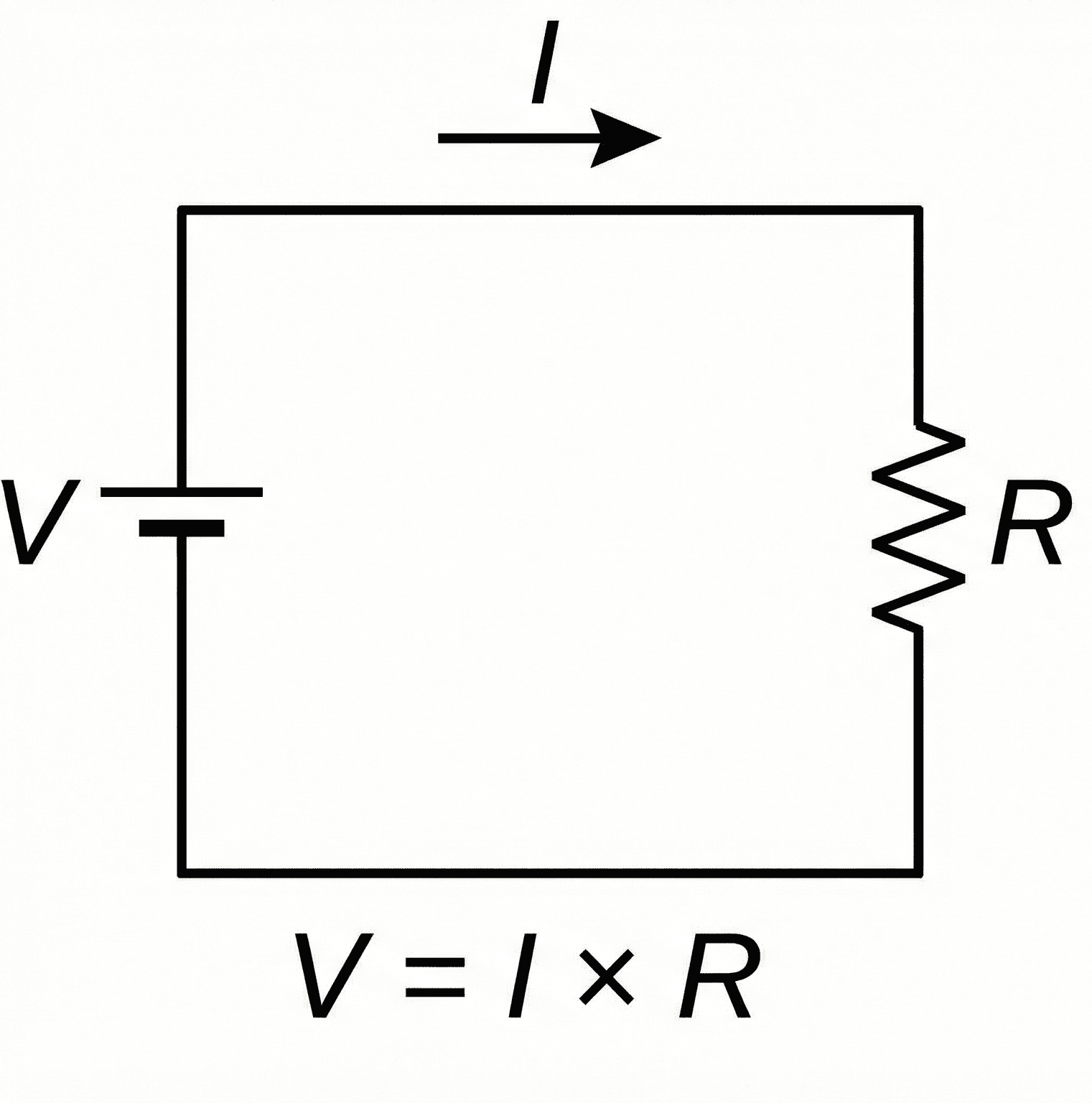
The first thing to notice is proportionality. Higher voltage increases current for the same resistance, while higher resistance decreases current for the same voltage.
What is Ohm’s Law?
Ohm’s Law is the core relationship between voltage, current, and resistance in an electrical circuit. It is one of the first equations used in circuit analysis because it turns a simple circuit diagram into measurable values.
In engineering language, voltage provides the potential difference that drives charge movement, current is the rate of charge flow, and resistance is the opposition to that flow. For an ohmic component, the ratio between voltage and current stays approximately constant.
Ohm’s Law is often the starting point for circuit analysis, voltage dividers, current checks, resistor sizing, sensor circuits, and power dissipation checks.
The Ohm’s Law formula
The standard form of Ohm’s Law is:
This equation says the voltage across a component equals the current through it multiplied by its resistance. It is most often used for resistors and other approximately linear, ohmic elements.
Ohm’s Law is often paired with electrical power equations:
Combining \(V = IR\) with \(P = VI\) gives common resistor power checks:
Do not stop at voltage, current, or resistance alone. Always check component power rating because a numerically correct Ohm’s Law result can still overheat a resistor or damage a device.
Variables and units
Ohm’s Law uses three base circuit quantities. Unit consistency is essential, especially when using milliamps, kilo-ohms, or mega-ohms.
- \(V\) Voltage or potential difference across a component. Unit: volts (V).
- \(I\) Current through the component. Unit: amperes (A). Common practical units include mA and µA.
- \(R\) Electrical resistance. Unit: ohms (\(\Omega\)). Common practical units include k\(\Omega\) and M\(\Omega\).
- \(P\) Electrical power dissipated or delivered. Unit: watts (W). Useful for checking component heating.
Use volts, amperes, and ohms together. Convert \(20\,\text{mA}\) to \(0.020\,\text{A}\), and convert \(2.2\,\text{k}\Omega\) to \(2200\,\Omega\) before calculating.
| Variable | Meaning | SI unit | Common practical units | Engineering note |
|---|---|---|---|---|
| \(V\) | Voltage | V | mV, V, kV | Measure across a component or between two nodes. |
| \(I\) | Current | A | µA, mA, A | Measure through a component or branch. |
| \(R\) | Resistance | \(\Omega\) | \(\Omega\), k\(\Omega\), M\(\Omega\) | Resistance may change with temperature and tolerance. |
| \(P\) | Power | W | mW, W, kW | Check against the component or supply rating. |
A \(1\,\text{k}\Omega\) resistor on a \(5\,\text{V}\) supply draws about \(5\,\text{mA}\). That quick mental check catches many k\(\Omega\), mA, and decimal-place mistakes.
How to rearrange Ohm’s Law
Ohm’s Law can solve for any one of the three main variables when the other two are known. The key is to choose the form that matches your unknown.
After rearranging, check the unit result. \(V/R\) should give amperes, \(V/I\) should give ohms, and \(IR\) should give volts.
Worked example: find current through a resistor
Example problem
A \(12\,\text{V}\) DC source is connected across a \(2.2\,\text{k}\Omega\) resistor. Find the current and estimate the resistor power.
Convert resistance to ohms:
Use the solve-for-current form:
The current is:
Now check power:
A \(0.065\,\text{W}\) result is below a common \(0.25\,\text{W}\) resistor rating, but a real design should still account for tolerance, temperature, enclosure heat, and derating.
Where engineers use Ohm’s Law
Ohm’s Law is used anywhere voltage, current, and resistance must be connected in a practical circuit. It is also the building block behind more advanced circuit equations.
- Resistor sizing: selecting resistance values for LEDs, pull-ups, pull-downs, sensors, and bias networks.
- Voltage dividers: deriving output voltage from resistor ratios and checking divider current.
- Power checks: estimating resistor heating, load current, and supply demand before choosing components.
- Troubleshooting: comparing measured voltage and current to expected resistance or load behavior.
- AC circuits: extending the same idea into impedance when resistance, capacitance, and inductance are frequency-dependent.
Use Ohm’s Law when the element behaves like a resistor under the operating condition. Use a diode model, transistor model, impedance model, or manufacturer curve when voltage-current behavior is nonlinear or frequency-dependent.
Assumptions and limitations
Ohm’s Law is reliable for ohmic conductors and resistors operating within their rated range. It becomes less reliable when the component’s resistance changes with voltage, current, temperature, light, magnetic field, or frequency.
- 1 The component behaves approximately ohmically over the operating range.
- 2 Resistance is known and reasonably constant for the temperature and current level.
- 3 Voltage and current are measured across and through the same element.
- 4 Power dissipation stays within the component’s safe operating limits.
Where the simple form breaks down
Do not expect a fixed resistance model for LEDs, diodes, transistors, batteries, motors, lamps during warm-up, thermistors, varistors, semiconductors, or components operating outside their ratings.
Ohm’s Law still helps locally, but nonlinear devices need device curves or models. A diode, for example, does not have one constant resistance across all voltages.
Engineering judgment and field reality
Real circuits are affected by tolerance, heating, wiring, connectors, supply limits, and measurement setup. Ohm’s Law gives the ideal relationship, but the real system may include extra resistance or changing resistance.
A load may measure correctly with a multimeter when unpowered but behave differently under load because of heating, poor contacts, voltage sag, corroded terminals, or supply current limiting.
When troubleshooting, measure voltage under load before assuming the resistor or load value is wrong. A weak supply or bad connection can make the Ohm’s Law calculation look inconsistent.
Common mistakes and engineering checks
- Mixing units: entering mA as A or k\(\Omega\) as \(\Omega\) can create 1000× errors.
- Ignoring power: a resistor can have the correct resistance but the wrong wattage rating.
- Using Ohm’s Law on nonlinear devices: LEDs, diodes, and transistors need more than one fixed resistance value.
- Measuring current incorrectly: current must be measured in series, not across the component like voltage.
- Forgetting tolerance: real resistors may vary from their nominal value, especially with heat and manufacturing tolerance.
If resistance increases and voltage stays the same, current should decrease. If your answer moves the other way, the equation was rearranged incorrectly.
| Check item | What to verify | Why it matters |
|---|---|---|
| Units | Convert mA to A and k\(\Omega\) to \(\Omega\) | Prevents 1000× errors |
| Power rating | Check \(P = VI\), \(P=I^2R\), or \(P=V^2/R\) | Prevents overheating components |
| Measurement location | Measure voltage across and current through the same element | Ensures the variables refer to the same component |
| Device behavior | Confirm the part is approximately ohmic | Nonlinear components need a different model |
Frequently asked questions
Ohm’s Law states that voltage equals current multiplied by resistance, written as \(V = IR\). It describes how voltage, current, and resistance relate in an ohmic circuit element.
The three common forms are \(V = IR\), \(I = V/R\), and \(R = V/I\). Use the form that isolates your unknown variable.
Voltage is measured in volts (V), current in amperes (A), and resistance in ohms (\(\Omega\)). Convert mA to A and k\(\Omega\) to \(\Omega\) before calculating.
Ohm’s Law is less accurate for nonlinear or temperature-dependent devices such as diodes, LEDs, thermistors, batteries, motors, lamps during warm-up, and semiconductors.
Summary and next steps
Ohm’s Law is the foundational circuit equation relating voltage, current, and resistance. The main form is \(V = IR\), and it can be rearranged to solve for current or resistance when the other two values are known.
The most important engineering judgment is knowing whether the component behaves like a resistor under the actual operating conditions. For real circuits, also check units, power rating, tolerance, heat, supply limits, and whether nonlinear behavior matters.
Where to go next
Continue your learning path with these curated next steps.
-
Prerequisite: Circuit Analysis
Build the broader foundation behind voltage, current, resistance, circuit elements, and analysis methods.
-
Current topic: Ohm’s Law
Use this page as your reference for \(V = IR\), units, rearranged forms, assumptions, and checks.
-
Advanced: Impedance Calculator
Move from DC resistance into AC circuit behavior with capacitors, inductors, frequency, and impedance.