
Key Takeaways
- Core idea: A smart grid adds sensors, communications, software, automation, and control systems to the physical electric grid.
- Engineering use: Smart grids help utilities manage outages, voltage, demand response, DERs, batteries, EV charging, and renewable variability.
- What controls it: Performance depends on data quality, communications reliability, control authority, cybersecurity, interoperability, and accurate feeder models.
- Practical check: A smart grid is not just smart meters; the real value comes from turning trusted field data into safe, coordinated grid actions.
Table of Contents
Introduction
Smart grids are electric power networks that use digital sensors, communications, automation, and control systems to monitor and manage electricity in real time. In power systems engineering, a smart grid is not just a smart meter system; it is a coordinated layer of field devices, data platforms, and control actions built on top of the physical grid.
How a Smart Grid Works
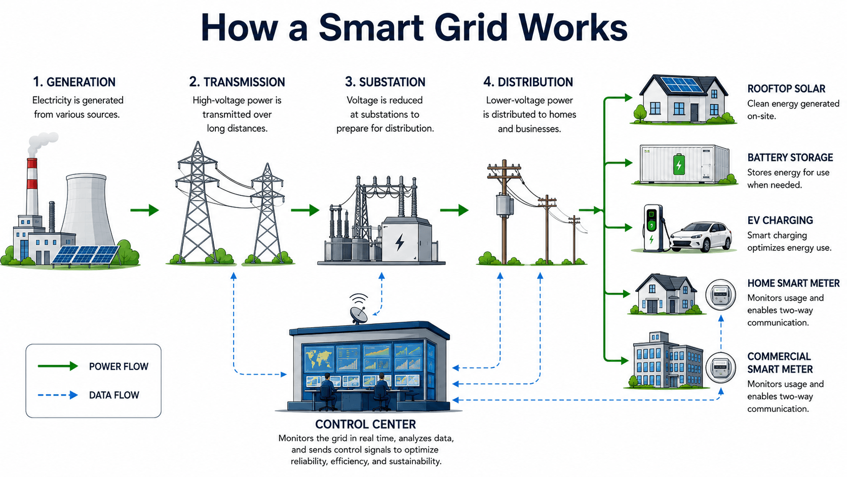
The green arrows represent electric power flow. The blue dashed arrows represent data flow. The smart grid function comes from using that data to support monitoring, decision-making, and control.
What Is a Smart Grid?
A smart grid is a digitally enhanced electric grid that combines power equipment with communication networks, measurement devices, automation, and software controls. Traditional grids were designed mainly around centralized generation and one-way power delivery. Smart grids add real-time visibility and coordinated control so operators can better manage variable demand, outages, distributed energy resources, voltage, and equipment loading.
The important engineering point is that “smart” does not replace the physical grid. Conductors, transformers, substations, switchgear, relays, meters, and feeders still set the electrical limits. The smart layer improves how those assets are monitored and operated, but it cannot ignore thermal ratings, voltage limits, protection settings, communications failures, or the physics of power flow.
Smart meters are usually part of a smart grid, but they are not the whole grid. A meter reports usage and service status; a smart grid uses many data sources and control devices to make system-level operating decisions.
Why Smart Grids Are Needed Now
Smart grids became important because the electric grid is being asked to do more than it was originally designed to do. Modern power systems must handle aging infrastructure, more rooftop solar, battery storage, EV charging, extreme weather, higher customer expectations, two-way power flow, and more flexible loads.
In a conventional feeder, a utility may only know that a problem occurred after a breaker trips, a customer calls, or a crew investigates. In a smart grid, devices can report voltage, current, power, meter status, switching state, DER output, and equipment alarms. That visibility helps operators move from delayed reaction toward faster detection, better diagnosis, and more targeted control.
| Grid pressure | Why it matters | Smart grid response |
|---|---|---|
| Rooftop solar growth | Solar output can create midday voltage rise, reverse power flow, and changing feeder loading. | Use voltage monitoring, smart inverter settings, DERMS, and feeder analytics to coordinate operation. |
| EV charging load | EV charging can add large evening loads in residential or commercial areas. | Use managed charging, load forecasts, transformer monitoring, and demand response programs. |
| Extreme weather | Storms can damage multiple feeders and interrupt communications at the same time. | Use automated outage detection, switching, crew prioritization, and restoration verification. |
| Aging equipment | Older assets may operate closer to thermal, mechanical, or reliability limits. | Use condition data, loading history, alarms, and operations records to guide maintenance and replacement. |
| Customer expectations | Customers expect faster outage updates, better reliability, and more control over energy use. | Use AMI, outage management systems, customer portals, and real-time service status data. |
Smart Grid Architecture: Power Layer, Data Layer, and Control Layer
A smart grid is easier to understand when separated into layers. The physical grid carries energy. The measurement layer observes what is happening. The communications layer moves data. The software layer analyzes the system. The control layer changes device behavior or operating state.
| Architecture layer | Typical elements | Engineering purpose |
|---|---|---|
| Physical power layer | Generators, transmission lines, substations, transformers, distribution feeders, switches, meters, DERs, and customer loads. | Moves electric power and sets the actual voltage, current, thermal, protection, and reliability limits. |
| Measurement layer | Smart meters, feeder sensors, relays, PMUs, line monitors, inverter telemetry, transformer monitors, and substation devices. | Provides visibility into voltage, current, power, frequency, loading, equipment status, alarms, and service interruptions. |
| Communications layer | Fiber, radio, cellular, utility private networks, field area networks, substation networks, and secure data pathways. | Moves measurements and control signals between field devices, substations, control centers, and data platforms. |
| Data and platform layer | SCADA, OMS, ADMS, DERMS, meter data management, GIS, historian systems, forecasts, and analytics platforms. | Turns field data into operating awareness, switching plans, outage information, DER coordination, and planning insight. |
| Control layer | Breaker commands, recloser operation, regulator tap changes, capacitor switching, inverter setpoints, battery dispatch, and demand response. | Executes actions that change feeder configuration, voltage profile, DER output, or load behavior. |
Most smart grid failures are not caused by a single missing technology. They usually happen when these layers do not line up: the physical feeder model is wrong, the data is incomplete, the communication path is unreliable, or the control action is not allowed under real operating conditions.
Smart Grid vs. Traditional Grid
The difference between a smart grid and a traditional grid is not just newer equipment. The practical difference is visibility and response. A traditional distribution system may only show limited feeder status until a customer calls, a breaker trips, or a crew investigates. A smart grid can collect field measurements, detect abnormal conditions sooner, and support automated or operator-directed actions.
| Grid feature | Traditional grid behavior | Smart grid behavior |
|---|---|---|
| Information flow | Limited field visibility; data often comes from SCADA points, customer calls, periodic inspections, or manual readings. | Two-way data from smart meters, feeder sensors, substations, automated switches, DERs, and control platforms. |
| Customer-side resources | Loads are mostly treated as passive demand connected to the distribution system. | Solar, batteries, EV chargers, controllable loads, and smart inverters can become active operating resources. |
| Outage response | Fault location and restoration may depend heavily on protection operation, customer reports, and field crew patrols. | Outage management systems, meter status, feeder automation, and switching logic can help locate and isolate faults faster. |
| Voltage management | Voltage regulators, capacitor banks, and transformer taps may be controlled by local settings or scheduled operation. | Voltage control can use feeder measurements, DER output, load forecasts, capacitor control, regulator settings, and smart inverter functions. |
| Operational risk | Fewer connected devices can mean less cyber exposure, but also less visibility. | Better visibility and automation, but increased dependence on communications, cybersecurity, interoperability, and data quality. |
Smart Grid Technologies Commonly Used in Power Systems
Smart grid technology is not one device. It is a group of systems that work together across metering, substations, distribution feeders, customer loads, and utility operations. The exact technology mix depends on whether the utility is solving outage response, voltage control, DER coordination, demand response, asset monitoring, or planning-data problems.
| Technology | What it does | Where it adds value |
|---|---|---|
| Advanced metering infrastructure | Collects usage intervals, meter status, outage indications, and sometimes voltage information. | Customer energy data, outage confirmation, demand response, load research, and voltage visibility. |
| Distribution automation | Uses automated switches, reclosers, sensors, and logic to operate feeders remotely or automatically. | Fault isolation, service restoration, feeder reconfiguration, and reliability improvement. |
| SCADA | Monitors and controls substations, breakers, transformers, and major grid equipment. | Remote operation, alarms, status monitoring, event review, and control center visibility. |
| Outage management system | Combines customer reports, meter status, feeder data, and network models to estimate outage location and restoration status. | Storm response, crew dispatch, customer communication, and restoration tracking. |
| ADMS | Supports distribution operations, switching, voltage optimization, state estimation, and feeder visualization. | Real-time distribution management and coordination of field devices. |
| DERMS | Coordinates distributed resources such as solar, batteries, smart inverters, EV charging, and controllable loads. | DER dispatch, curtailment, voltage support, managed charging, and flexible load coordination. |
| Smart inverters | Allow inverter-based resources to support voltage, reactive power, ride-through, and communication functions. | High-DER feeders, voltage control, solar integration, and distributed resource coordination. |
| Forecasting and analytics | Uses historical data, weather, load trends, DER output, and operating data to estimate future grid conditions. | Peak management, DER planning, outage preparation, and operational decision support. |
The Smart Grid Control Loop
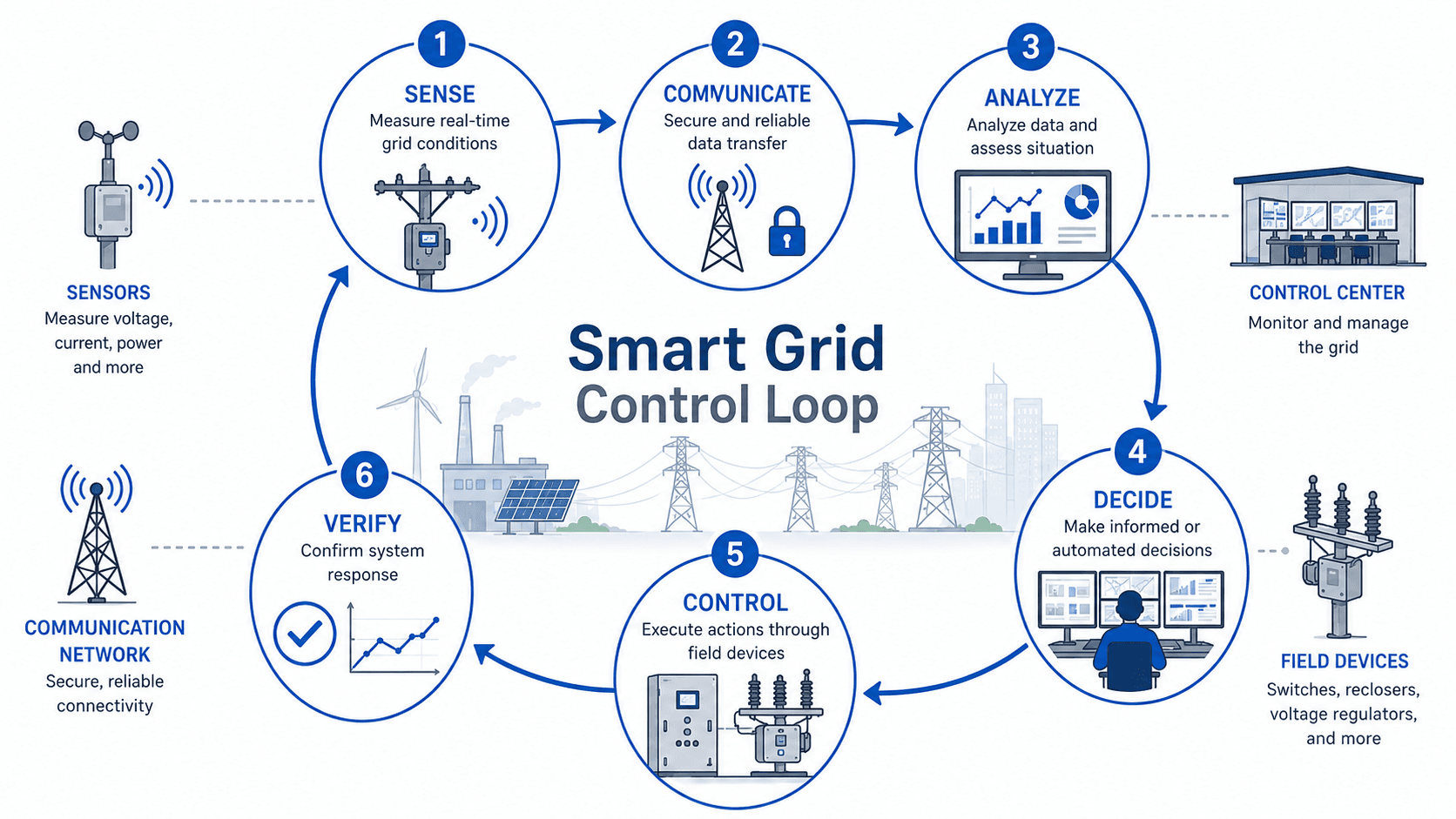
Smart grids work as a feedback control problem: measure the system, communicate the data, analyze conditions, decide what action is needed, control field equipment, and verify that the system responded correctly. This loop may involve automated logic, operator approval, or both depending on the function and risk level.
Sense: measure the grid condition
Sensors, meters, relays, phasor measurement units, smart inverters, and substation devices provide information about voltage, current, power, frequency, device status, alarms, and customer-side usage. The usefulness of the control loop depends on whether the measured points actually represent the electrical conditions that matter.
Communicate: move data reliably and securely
Communications may use fiber, cellular, radio, utility private networks, or other systems. A smart grid design must consider latency, bandwidth, coverage, redundancy, device authentication, and what happens if communication fails during a storm or abnormal system condition.
Control and verify: take action without losing trust
Control actions may include switching feeders, changing voltage regulator taps, dispatching battery storage, adjusting inverter setpoints, curtailing DER output, or triggering demand response. Verification matters because a command is not the same as a confirmed system response.
Smart Grids and Distributed Energy Resources
Distributed energy resources change the operating problem because power is no longer supplied only from large central plants. Rooftop solar, community batteries, EV chargers, smart inverters, backup generation, and flexible loads can all affect feeder voltage, peak demand, load shape, and power direction.
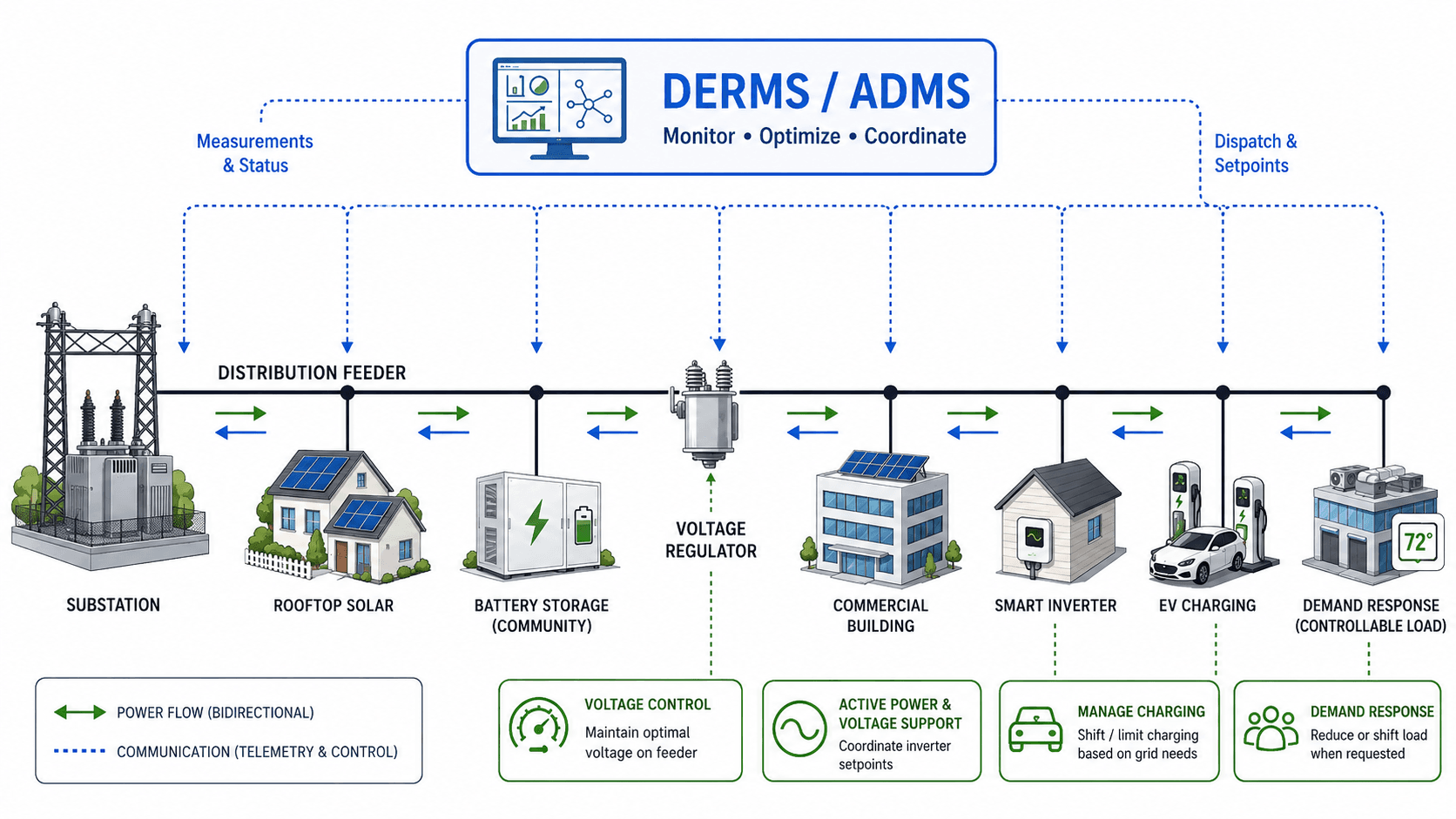
ADMS is typically focused on distribution operations such as feeder status, switching, voltage management, and outage response. DERMS is focused on coordinating distributed resources. In practice, the two systems may exchange telemetry, forecasts, dispatch instructions, setpoints, and operating constraints so the utility can coordinate field devices and customer-side resources.
Example: high-solar feeder with evening EV charging
Consider a residential feeder with high rooftop solar during the day and heavy EV charging in the evening. Midday solar may raise voltage near the end of the feeder, while evening EV charging may increase transformer and conductor loading. A smart grid approach could use voltage sensors, smart inverter setpoints, battery dispatch, and managed EV charging to keep voltage and equipment loading within acceptable limits.
DER coordination is only as good as the feeder model, communications, device settings, and customer participation behind it. A dashboard that shows DER capacity does not guarantee the utility can control that capacity during a real operating constraint.
Smart Grid Benefits and the Engineering Mechanisms Behind Them
Smart grids can improve reliability, efficiency, DER integration, and customer visibility, but the benefits are not automatic. Each benefit comes from a specific mechanism, and each mechanism introduces tradeoffs that must be managed.
| Smart grid benefit | How the benefit is created | Engineering tradeoff |
|---|---|---|
| Faster outage response | Automated switching, meter outage status, feeder sensors, and outage management analytics help narrow fault locations. | Switching logic must be coordinated with protection settings, abnormal feeder conditions, and field crew procedures. |
| Better voltage control | Measurements and controls can coordinate regulators, capacitors, transformer taps, and smart inverter setpoints. | Poor settings can cause hunting, customer voltage issues, or unintended interactions between devices. |
| Improved DER integration | DERMS, inverter functions, forecasts, and feeder data help manage solar, storage, EV charging, and demand response. | Control authority, customer participation, communications latency, and interconnection rules can limit what is possible. |
| Reduced peak stress | Demand response, storage dispatch, pricing signals, or managed EV charging can shift or reduce load. | The response must be dependable during the exact hours when the grid needs relief. |
| Improved planning data | Meter intervals, equipment status, and feeder measurements improve load modeling and asset utilization review. | Bad data, missing data, and inconsistent time alignment can mislead planning studies. |
| Better customer visibility | Smart meters and customer platforms can show usage patterns, outage status, and program participation. | Privacy, data security, customer understanding, and program design must be handled carefully. |
Smart Grid Planning vs. Smart Grid Operations
Smart grid data is useful in both long-term planning and real-time operations, but those workflows are different. Planning uses smart grid data to decide what the system should become. Operations uses smart grid data to decide what the system should do now.
| Planning use | Operations use | Why the difference matters |
|---|---|---|
| Estimate DER hosting capacity for feeders and circuits. | Adjust inverter setpoints or dispatch batteries during a voltage constraint. | Planning studies can identify risk, but operations must respond to real-time feeder conditions. |
| Forecast load growth from electrification, EVs, buildings, and development. | Use demand response or managed charging during peak demand periods. | Long-term forecasts guide upgrades; operating controls manage short-term stress. |
| Prioritize transformer, conductor, switchgear, and feeder upgrades. | Monitor alarms, loading, outage status, and abnormal events. | Asset planning depends on historical patterns, while operations depends on present system state. |
| Improve feeder models, GIS data, and customer load profiles. | Execute switching plans, restoration steps, or voltage optimization commands. | A clean model improves both workflows, but operating actions require higher confidence and clear fallback logic. |
Smart Grid Senior Engineer Review Checklist
A smart grid project should be reviewed as an engineering control system, not just an IT upgrade. The checklist below helps connect the technology to a real grid objective and reduces the risk of installing sensors, software, or automation that does not produce useful operating value.
Define the grid problem, confirm the field measurements, verify the communication path, decide what control action is allowed, test the fallback mode, and confirm that operators can interpret the result under abnormal conditions.
| Review check | What to look for | Why it matters |
|---|---|---|
| Operating objective | A clear target such as outage restoration, voltage optimization, DER coordination, peak reduction, or situational awareness. | Vague modernization goals often lead to equipment purchases without measurable grid performance improvement. |
| Measurement coverage | Sensors, meters, relays, inverter data, or substation points located where they can represent the condition being controlled. | Automation can only act correctly if the measured data reflects the actual feeder condition. |
| Communications resilience | Latency, redundancy, coverage, cybersecurity, and fallback behavior during outage or storm conditions. | The grid is often most stressed when communications are also most vulnerable. |
| Control authority | Confirmed ability to switch devices, adjust regulator taps, change inverter setpoints, dispatch batteries, or manage loads. | Monitoring without control may improve awareness but will not directly correct a feeder constraint. |
| Protection coordination | Review of recloser, breaker, fuse, relay, inverter, sectionalizer, and switching behavior under bidirectional power flow. | Smart grid actions should not create unsafe fault clearing, miscoordination, or unintended islanding concerns. |
| Data quality | Time alignment, missing intervals, device status, feeder model accuracy, and consistent naming across systems. | Bad telemetry or inaccurate network data can make the control system appear more accurate than it really is. |
| Operator usability | Clear alarms, dashboards, procedures, override paths, and training for abnormal operating states. | A smart grid system that operators do not trust or understand will be bypassed during real events. |
| Verification method | A way to confirm that the commanded action changed voltage, loading, outage state, DER output, or load as expected. | Without verification, the system cannot distinguish between a successful control action and a failed command. |
Engineering Judgment and Field Reality
Smart grid diagrams often show clean arrows and smooth digital control, but real power systems are messier. Feeders may have outdated maps, unknown switching states, mixed equipment ages, communication gaps, non-standard customer DER installations, and protection settings that were not designed for high bidirectional power flow.
Data quality can control the outcome
Time alignment matters when comparing meter intervals, feeder telemetry, inverter output, weather, and outage records. Missing data can distort load analysis. Incorrect device status can mislead switching decisions. A smart grid system should include validation logic so operators know when data is stale, missing, or inconsistent.
Protection coordination still comes first
Automated switching and distributed generation can change fault current paths and restoration sequences. Reclosers, breakers, fuses, relays, sectionalizers, inverter ride-through settings, and islanding logic must still be reviewed as a coordinated protection system. Smart grid automation should not create a condition that restores load into an unsafe or poorly protected configuration.
The most useful smart grid systems are not the ones with the most screens. They are the ones where operators can trust the data, understand the recommended action, override automation when necessary, and verify the result.
When Smart Grid Assumptions Break Down
Smart grids can improve visibility and response, but they do not automatically solve every power system problem. The physical grid still has finite capacity, equipment still fails, severe weather still causes damage, and automation still depends on correct settings, communications, data, and operating procedures.
- Insufficient physical capacity: sensors and dashboards cannot remove conductor, transformer, substation, or transmission capacity limits.
- Bad or missing data: stale meter intervals, failed sensors, incorrect device status, or poorly synchronized timestamps can cause the control system to misread conditions.
- Communications failure: automation that depends on field communications must have safe fallback behavior when links are slow, degraded, or unavailable.
- Model mismatch: ADMS and DERMS decisions can be wrong when feeder connectivity, transformer ratings, switch positions, or customer DER records are inaccurate.
- Protection conflicts: bidirectional power flow, inverter behavior, and automated switching can affect relay, recloser, fuse, and breaker coordination.
- Cybersecurity exposure: every connected device and control path adds potential access points that must be managed throughout the asset life.
- Customer non-participation: demand response, managed charging, and flexible load programs depend on actual customer or device response when called.
The most dangerous assumption is that more data automatically means better control. Smart grid value comes from trustworthy data, correct interpretation, safe control authority, and verified response.
Smart Grid vs. Microgrid vs. Virtual Power Plant
Smart grids are often confused with related terms. These concepts can overlap, but they are not the same thing. A smart grid is the broader modernization concept for monitoring and controlling the power system. Microgrids and virtual power plants are more specific operating structures that may use smart grid technologies.
| Term | What it means | Relationship to smart grids |
|---|---|---|
| Smart grid | A digitally monitored and controlled electric grid with sensors, communications, automation, and analytics. | The broad utility/grid modernization concept that can include many technologies and operating functions. |
| Microgrid | A local electric system that can sometimes operate connected to the utility grid or islanded from it. | May use smart grid controls locally for generation, storage, load, and islanding coordination. |
| Virtual power plant | An aggregation of DERs, storage, loads, or customer devices operated as a coordinated resource. | Often depends on smart grid communications, DERMS, telemetry, dispatch logic, and customer/device participation. |
| Smart meter | A customer meter with two-way communication and interval data capabilities. | One component of a smart grid, but not the entire smart grid system. |
Cybersecurity, Interoperability, and Smart Grid Reference Guidance
Smart grid engineering depends heavily on interoperability because devices, communication networks, software platforms, meters, DERs, and control systems often come from different vendors and operate across different utility functions. Cybersecurity also becomes a physical-grid issue because digital commands can affect switching, voltage control, DER behavior, load response, and restoration actions.
- NIST Smart Grid Framework: NIST Framework and Roadmap for Smart Grid Interoperability Standards, Release 4.0 provides authoritative guidance on smart grid conceptual models, communication pathways, cybersecurity practices, interoperability profiles, and testing concepts.
- Cybersecurity controls: Device authentication, role-based access, network segmentation, event monitoring, secure updates, incident response, and vendor management should be part of the engineering architecture.
- Interoperability controls: Data models, protocols, naming conventions, time synchronization, system interfaces, and testing plans help prevent smart grid projects from becoming isolated vendor-specific silos.
Frequently Asked Questions
A smart grid is an electric power network that uses sensors, communications, automation, and control systems to monitor and manage electricity in real time. It combines physical grid equipment with digital data systems so operators can detect problems, manage demand, coordinate distributed resources, and respond faster to changing grid conditions.
A traditional grid mainly delivers power from central generation through transmission and distribution equipment with limited real-time visibility. A smart grid adds two-way data communication, automated switching, advanced metering, digital controls, and software platforms that help operators detect problems, manage voltage, coordinate distributed resources, and respond faster to changing conditions.
No. Smart meters are one part of a smart grid, but they are not the whole system. A complete smart grid may also include feeder sensors, reclosers, voltage regulators, communications networks, control centers, outage management systems, DERMS, ADMS, smart inverters, batteries, EV charging coordination, and cybersecurity controls.
Smart grids are important for renewable energy because solar, wind, batteries, and electric vehicles change power flow, voltage behavior, and operating conditions throughout the day. Smart grid systems give operators better visibility and control so distributed resources can be monitored, limited, dispatched, or coordinated instead of behaving like unmanaged devices on the feeder.
Smart grids can reduce outage duration, improve fault detection, support faster restoration, and help operators respond to abnormal conditions, but they cannot prevent every blackout. Extreme weather, equipment failure, transmission constraints, fuel supply issues, cyber incidents, protection problems, and planning limits can still affect the power system.
Summary and Next Steps
Smart grids combine physical power infrastructure with digital measurement, communications, analytics, and control. The result is a grid that can respond more intelligently to outages, voltage problems, renewable variability, distributed energy resources, demand response, and changing customer behavior.
The most important engineering idea is the feedback loop: sense the system, communicate data, analyze conditions, decide on an action, control field devices, and verify the response. A strong smart grid design connects that loop to real operating constraints such as voltage limits, thermal ratings, protection coordination, cybersecurity, interoperability, and communications resilience.
Where to go next
Continue your learning path with related Turn2Engineering resources.
-
Power Systems Engineering
Start with the broader generation, transmission, distribution, protection, and control concepts that frame smart grid design.
-
Power Generation
Review how electric power is produced before it is transmitted, distributed, monitored, and coordinated by modern grid systems.
-
Power Distribution
Learn how lower-voltage distribution networks deliver power to customers and why smart grid controls are especially important on feeders.