Key Takeaways
- Definition: Ground improvement is the deliberate modification of soil or weak rock to increase strength and stiffness, reduce settlement, improve drainage behavior, or lower geotechnical risk.
- Use case: Engineers use it when shallow foundations, slabs, embankments, or earthworks are preferred but native ground cannot meet performance targets on its own.
- Main decision: The core design task is matching the method to the soil profile, groundwater, construction constraints, and settlement or liquefaction requirements.
- Outcome: After reading, you should be able to compare major methods, understand what controls selection, and recognize where field verification matters more than a perfect-looking calculation.
Table of Contents
Introduction
In brief: Ground improvement makes difficult ground perform acceptably by changing its strength, stiffness, drainage, or density so the site can support the project more reliably.
Who it’s for: Students, FE/PE prep, and practicing designers.
For informational purposes only. See Terms and Conditions.
This page explains what ground improvement is, when engineers choose it over removal or deep foundations, and what controls whether a treatment works in the field.
Ground improvement infographic
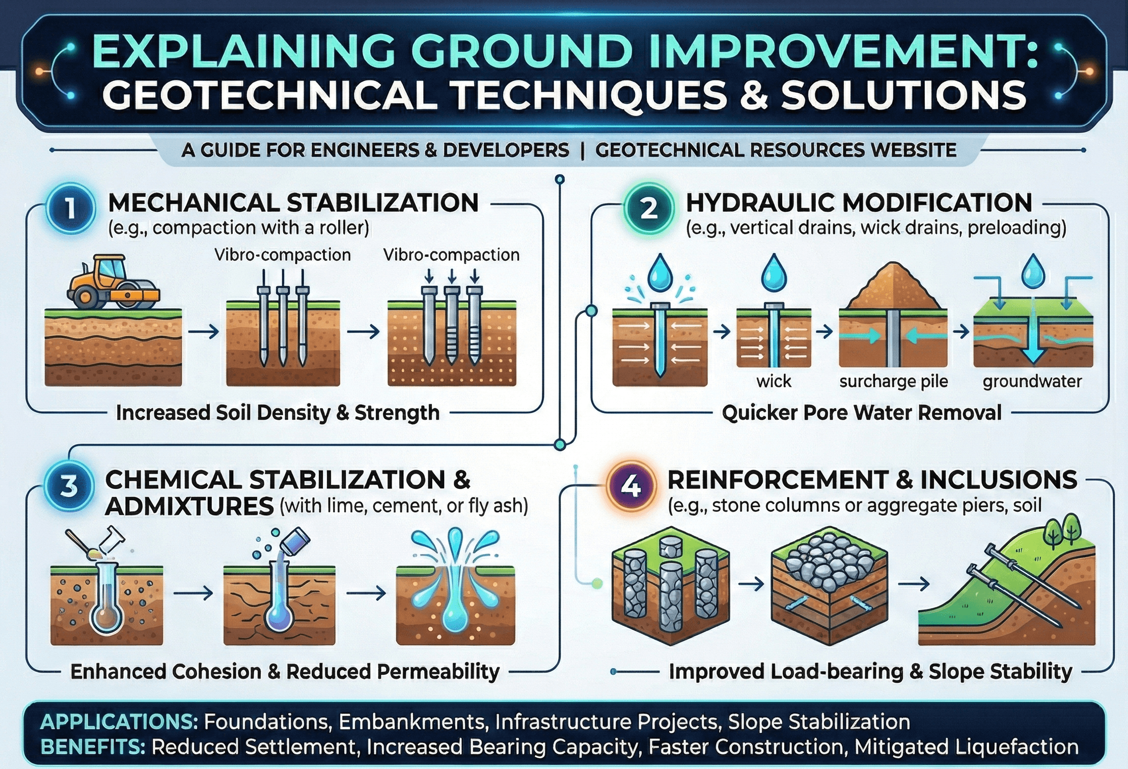
Start by noticing that the techniques are not interchangeable. Some methods densify granular soils, some accelerate consolidation in soft clays, some create reinforced composite ground, and others create low-permeability or higher-strength soil-cement zones. That is why method selection always starts with the ground model rather than the equipment list.
What is ground improvement?
Ground improvement is the geotechnical practice of modifying in-place soil or weak rock so the ground meets project performance requirements without fully bypassing it. Instead of accepting poor bearing, large settlements, liquefaction vulnerability, or problematic seepage, engineers change the ground itself through densification, drainage, reinforcement, replacement, mixing, grouting, or staged loading.
The reason this topic matters is simple: many projects are governed less by ultimate failure and more by serviceability, schedule, and constructability. A large warehouse slab may not need piles under every column, but it does need predictable settlement. A road embankment over soft clay may be stable in the long term, but not fast enough for the construction program unless consolidation is accelerated. A tank farm in loose saturated sand may carry the load, yet still face unacceptable seismic risk if liquefaction is ignored.
In practice, ground improvement sits between two common extremes. On one side is “do nothing and hope the ground is good enough.” On the other is “default to piles or full undercut.” The best solution is often in the middle: improve only what needs to be improved, to the degree required by the structure, and verify that the target performance was actually achieved.
If you are new to the broader topic cluster, start with What is Geotechnical Engineering and Soil Mechanics, then come back to this page with the mindset that ground improvement is really applied soil mechanics under project constraints.
Core principles, variables, and units
Ground improvement is not one formula. It is a collection of methods whose success depends on the same few fundamentals: effective stress, compressibility, drainage path, density, shear strength, and variability of the subsurface profile. Those principles tell you whether a treatment should densify, drain, reinforce, cement, replace, or simply redistribute load.
What usually controls the design
Most real projects are controlled by one or more of the following: allowable bearing pressure, total settlement, differential settlement, factor of safety against instability, rate of settlement, groundwater behavior, and seismic performance. The critical mistake is trying to improve “the soil” in a general sense without first stating the actual performance target.
- \( \sigma’ \) Effective stress; typically reported in kPa or psf. It governs strength and compressibility far better than total stress alone.
- \( s_u \) Undrained shear strength of clay, often in kPa or psf. Critical for short-term stability and soft-ground staging decisions.
- \( \varphi’ \) Effective friction angle, in degrees. Central for drained granular response, bearing, and stability checks.
- \( c_v \) Coefficient of consolidation, usually in m²/s or ft²/day. It controls how quickly surcharge and drains translate into settlement over time.
- \( k \) Hydraulic conductivity, commonly m/s or cm/s. Important in seepage, drain spacing, cutoff design, and dissipation behavior.
- \( a_s \) Area replacement ratio for column systems. It is a simple but useful first indicator of how much composite improvement you are installing.
Before comparing methods, define an acceptance statement such as “less than 25 mm total settlement and less than 1/500 differential rotation at service load.” That one sentence often narrows the shortlist immediately.
Typical method families
Densification methods such as vibro compaction and dynamic compaction work best when the soil can actually be rearranged into a denser state. Drainage-based methods such as surcharge with prefabricated vertical drains work when time-dependent settlement is the main issue. Reinforcement methods such as stone columns or geosynthetic platforms create composite ground behavior. Mixing and grouting methods increase stiffness or reduce permeability where soil response cannot be fixed by densification alone.
Decision logic or design workflow
A good ground improvement workflow starts with site conditions and performance targets, not brand names or contractor preferences. Engineers typically move through the process below.
1) Build the ground model from borings, CPT/SPT, groundwater observations, and lab data. 2) Define what is failing: bearing, settlement, differential movement, liquefaction, lateral stability, seepage, or schedule. 3) Decide whether you need densification, faster drainage, composite stiffness, lower permeability, or reduced stress. 4) Screen methods against access, vibration tolerance, spoils, groundwater, footprint size, and adjacent structures. 5) Set measurable acceptance criteria. 6) Confirm with trial sections, instrumentation, and post-treatment testing.
| Ground condition or project issue | Usually effective methods | Why they fit | What to verify |
|---|---|---|---|
| Loose clean sand with liquefaction concern | Vibro compaction, stone columns | Densifies soil and may improve drainage response | CPT/SPT gain, relative density, settlement and seismic criteria |
| Soft compressible clay beneath embankment or tank | Surcharge with PVDs, staged construction, stone columns, DSM | Accelerates consolidation or adds composite stiffness | Settlement plates, piezometers, stability factors, strength gain |
| Heterogeneous fill or local voiding | Dynamic compaction, rapid impact compaction, compaction grouting | Improves variable fill or treats localized weak zones | Production logs, test pits, probe refusal, surface settlements |
| Need lower permeability plus support | Deep soil mixing, jet grouting | Creates stronger and tighter treated mass | Core strength, geometry continuity, permeability checks |
This workflow connects naturally to adjacent topics like Foundation Design, Settlement Analysis, and Pile Foundations. Those pages answer the next question after you identify the ground problem: what structure-ground system gives the best overall result?
Equations and calculations
There is no single universal ground improvement equation because different methods improve the ground in different ways. Still, several relationships show up repeatedly in design screening and performance interpretation.
Effective stress is the foundation of most geotechnical behavior. If pore pressure rises, effective stress falls, and the ground may lose strength or become more compressible even when the visible load did not change. That is why groundwater and drainage are inseparable from ground improvement.
This time factor relationship helps explain surcharge and wick drain programs in soft clays. The message is intuitive: shorter drainage paths and higher consolidation coefficients produce faster settlement. Engineers often reduce the drainage path with prefabricated vertical drains instead of waiting years for natural consolidation.
For column-supported ground such as stone columns or rigid inclusions, area replacement ratio is a useful screening measure. It compares the area of treated columns to the tributary plan area they support. It does not by itself prove settlement performance, but it gives a fast sense of whether the grid is sparse, moderate, or aggressive.
Be cautious with elegant equations that hide weak assumptions. In ground improvement, the field geometry, continuity of treatment, and variability of the deposit often matter as much as the equation itself.
Worked example
Example: warehouse slab on soft clay over dense sand
A proposed warehouse will use a large floor slab with moderate loads over a site containing 4 to 6 m of soft clay above dense sand. Ultimate bearing failure is not the main problem. The geotechnical concern is total settlement, differential movement beneath rack aisles, and schedule pressure that does not allow a long waiting period before construction.
The first pass is not to ask “Should we use stone columns?” but rather “What performance do we need?” Suppose the slab system can tolerate about 25 mm total post-construction settlement in critical areas and modest differential movement. That immediately rules out simple shallow founding on untreated soft clay if consolidation would continue for years.
A practical shortlist might include: surcharge with wick drains to accelerate consolidation; stone columns to create a stiffer composite mass; or a hybrid solution using ground improvement beneath the slab and piles only at isolated heavy equipment pads. Removal and replacement may be uneconomical at this footprint, while full piling may oversolve the problem.
The designer then checks which mechanism matches the project driver. If time is the main issue and settlement can be tolerated before the slab is placed, surcharge plus drains is attractive. If immediate stiffness and lower differential movement are needed, stone columns or inclusions may be more effective. The final choice is then tied to verification: settlement plates and piezometers for preload, or modulus/CPT-type confirmation and production controls for column systems.
The lesson is that the “best” method is not the strongest method. It is the method that meets the structural tolerances, construction program, groundwater conditions, and budget with measurable confidence.
Engineering judgment and field reality
Ground improvement is one of the clearest examples of why field reality matters in geotechnical engineering. Two sites with the same average undrained strength or CPT resistance can behave very differently if one contains organics, thin weak seams, buried debris, artesian groundwater, or untreated edge zones. A method that looks perfect in a conceptual matrix can underperform badly when production begins.
Experienced engineers watch for three things early: whether the treatment mechanism matches the soil, whether the improvement zone actually covers the stress influence area, and whether the verification method is capable of detecting underperformance. Those are judgment issues, not just spreadsheet issues.
Contractors improve what they can reach. If utilities, obstructions, property lines, or working-platform limitations shrink the treatment footprint, the untreated margins can become the real source of differential settlement.
Another recurring field lesson is that groundwater rarely behaves as neatly as the investigation suggested. Seasonal fluctuations, perched water, drainage interference, and construction dewatering can all change effective stress conditions. That is why pages like Permeability Test and the broader geotechnical hub matter in design development: drainage response is often the hidden controller of performance.
When this breaks down
Ground improvement breaks down when designers treat it like a generic upgrade instead of a method-specific response. Vibro compaction loses effectiveness as fines increase. Surcharge programs disappoint when drainage assumptions are too optimistic or the fill cannot remain stable during staging. Stone columns may not deliver the expected settlement reduction if the surrounding matrix is too weak, too organic, or too variable. Mixing and grouting can struggle with continuity, spoil management, or geometry control when subsurface obstructions are widespread.
It also breaks down when project tolerances are stricter than the method can realistically deliver. Some structures can tolerate a predictable amount of movement; others cannot. If the true requirement is near-zero differential settlement at isolated heavy load points, a hybrid system or deep foundations may be the right answer.
Finally, ground improvement fails conceptually when verification is weak. A design that depends on strength gain, density increase, or accelerated consolidation is only as credible as the field measurements that prove those outcomes were achieved.
Common pitfalls and engineering checks
- Using the average soil property rather than the controlling layer or weakest zone.
- Choosing a method based on equipment familiarity instead of soil compatibility.
- Checking bearing capacity but ignoring differential settlement and serviceability.
- Stopping treatment at the foundation edge instead of extending into the stress influence zone.
- Overlooking groundwater, drainage boundaries, or dewatering effects during construction.
- Specifying acceptance criteria that sound technical but are impossible to verify in the field.
One of the most expensive mistakes is comparing methods using only first cost. A cheaper treatment that leaves the project with ongoing slab repairs, track misalignment, pavement rutting, or tank settlement is rarely the true low-cost option.
| Parameter | Symbol | Typical units | Notes |
|---|---|---|---|
| Effective stress | \( \sigma’ \) | kPa, psf | Controls much of soil strength and deformation behavior. |
| Undrained shear strength | \( s_u \) | kPa, psf | Critical in short-term clay response and staged embankment checks. |
| Coefficient of consolidation | \( c_v \) | m²/s, ft²/day | Key to preload duration and drain spacing assumptions. |
| Hydraulic conductivity | \( k \) | m/s, cm/s | Influences drainage, seepage, and dissipation behavior. |
| Area replacement ratio | \( a_s \) | dimensionless | Useful screening metric for column-supported ground. |
Visualizing ground improvement in practice
A helpful way to visualize this topic is to think in layers and mechanisms. Shallow loose sands respond to densification. Soft saturated clays respond to staged loading and drainage. Variable fills may need impact energy or local grouting. Areas needing both support and seepage control often move toward mixing or jet grouting.
That mental model helps prevent a common beginner error: assuming every weak site should be fixed with the same family of techniques. Ground improvement is really a map from geologic problem to treatment mechanism.
Keep asking: are we trying to densify, drain, reinforce, cement, replace, or reduce stress?
Relevant standards and design references
Ground improvement is strongly shaped by project-specific specifications, agency manuals, and method-specific QA requirements. A strong design package ties calculations to measurable construction and acceptance criteria.
- ASTM D698 / D1557: Standard and modified Proctor compaction references used when engineered fill, replacement layers, and working platforms depend on moisture-density control.
- ASTM D2435: One-dimensional consolidation testing used to estimate compressibility and settlement-time behavior for surcharge and drain programs.
- ASTM D1586 and ASTM D5778: SPT and CPT-related exploration methods that frequently support method screening and post-treatment verification.
- FHWA and USACE guidance: Widely used for embankments, soft-ground treatment, stone columns, grouting, and performance monitoring on transportation and civil infrastructure projects.
- Project-specific specifications: Often the most important document because they define hold points, production logs, instrumentation requirements, acceptance thresholds, and corrective action procedures.
Frequently asked questions
Use ground improvement when you want the near-surface ground itself to perform better across an area, especially under slabs, embankments, tanks, or shallow foundations. Use piles when the project needs load transfer to deeper competent layers or when movement tolerances are too strict for area treatment alone.
No. It reduces settlement, accelerates it, redistributes it, or makes it more predictable. The correct design goal is usually acceptable total and differential settlement, not zero movement.
The most common reason is mismatch between the method and the actual subsurface conditions, often made worse by incomplete investigation or weak verification. In geotechnics, a good-looking design can still fail if the treated zone, groundwater assumptions, or field controls are wrong.
It is common beneath warehouse slabs, bridge approaches, embankments, pavements, tanks, port reclamation, retaining systems, working platforms, and liquefaction mitigation zones where large footprints or schedule constraints make other options less attractive.
Summary and next steps
Ground improvement is not about making soil “good.” It is about making the ground perform well enough for the structure, the construction sequence, and the lifecycle demands of the project. That distinction matters because the target may be strength, settlement reduction, faster consolidation, lower permeability, liquefaction mitigation, or simply more consistent support under a large footprint.
The strongest ground improvement designs begin with a clear ground model and a clear performance statement. From there, the engineer matches the treatment mechanism to the soil profile, checks constructability and groundwater behavior, and defines how success will be verified in the field. In many projects, that field verification is the real source of confidence.
If you remember one practical lesson, let it be this: the right method is the one that solves the controlling geotechnical problem with measurable, buildable, and economically justified performance.
Where to go next
Continue your learning path with these curated next steps.
-
Read a deeper dive on Soil Mechanics
Build the effective stress, strength, seepage, and compressibility intuition behind every ground improvement decision.
-
Study Settlement Analysis
Useful when the next step is checking whether untreated, treated, or hybrid ground systems can meet serviceability limits.
-
Practice with the Terzaghi Bearing Capacity Calculator
Apply related shallow foundation concepts numerically when bearing and settlement screening are part of the workflow.