Key Takeaways
- Definition: A pile foundation is a deep foundation system that transfers structural loads to deeper soil or rock through shaft resistance, end bearing, or a combination of both.
- Use case: Piles are selected when near-surface soils are too weak or compressible, when uplift or lateral loads are high, or when scour and groundwater make shallow systems unreliable.
- Main decision: The biggest engineering choice is not just pile type, but matching the ground profile, installation method, performance criteria, and field verification plan.
- Outcome: After reading, you should understand how pile foundations work, what controls design, and where simplified calculations stop being enough.
Table of Contents
Introduction
Direct answer: Pile foundations are deep foundation elements used when shallow footings cannot safely control bearing, settlement, uplift, or lateral demands. They transfer load to deeper competent strata or mobilize resistance along the pile shaft, making them essential for bridges, towers, waterfront structures, soft-ground sites, and high-load foundations.
This page is for engineering students, FE/PE candidates, and practicing engineers who need a practical explanation of pile foundations rather than a vague definition. You will see where piles make sense, how capacity is developed, what checks matter beyond a single equation, and how field installation can change the behavior you assumed on paper.
Pile foundations infographic
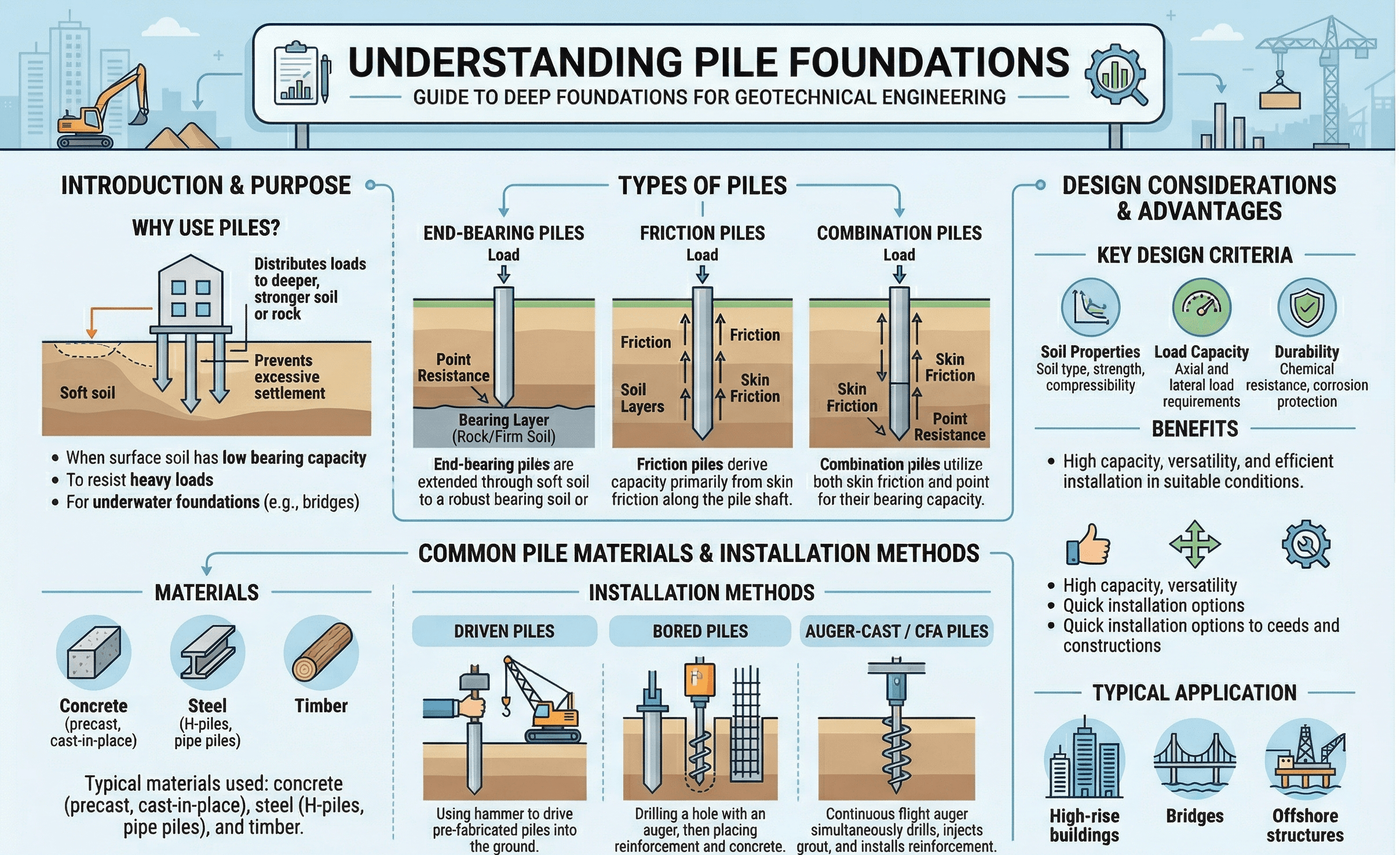
The first thing to notice is that piles do not rely on one single mechanism. Some designs are mainly friction piles, some are mainly end-bearing piles, and many real piles use both. The diagram is most useful when you read it together with the ground profile and ask which layer actually controls performance.
What are pile foundations?
A pile foundation is a deep foundation system made of long, slender elements installed into the ground to support structural loads below weak or problematic surface soils. Unlike a spread footing that works near grade, a pile foundation reaches deeper layers where strength, stiffness, or confinement are more reliable.
In practice, pile foundations are used when a shallow foundation would settle too much, when uplift or lateral loads matter, when scour threatens near-surface support, or when construction needs to bypass uncontrolled fill, organic soils, liquefiable layers, or soft clay. They are common beneath bridge piers, marine structures, towers, high-rise buildings, industrial slabs with heavy reactions, and retaining or excavation support systems.
Engineers usually divide piles by material and installation method: driven steel or concrete piles, drilled shafts, augercast piles, micropiles, helical piles, and other project-specific systems. The “best” option is rarely the one with the highest textbook capacity. It is the one that can be installed predictably, verified in the field, and connected cleanly to the structure at the required level of performance.
Core principles, variables, and units
Pile design starts with a simple question: where does the resistance come from? A pile can resist compression by end bearing at the tip, by shaft resistance along the embedded length, or by both. It can also resist uplift, lateral load, and moment depending on stiffness, fixity, group arrangement, and the surrounding soil response.
Key variables and typical ranges
The variables below show up repeatedly in design reports, load test interpretation, and preliminary sizing. Typical ranges vary widely by pile type and soil profile, so these are sanity-check concepts rather than universal numbers.
- Q Axial load or nominal axial resistance; typically kN or kips.
- Qs Shaft resistance developed along the pile-soil interface; often governs in long piles through sand or clay.
- Qb End bearing at the pile tip; can dominate when the pile bears in dense sand, stiff soil, or rock.
- L Embedded pile length; usually reported in m or ft and strongly tied to both capacity and deflection.
- D Pile diameter or characteristic width; affects stiffness, side area, and toe area.
- s Pile spacing within a group; often expressed in pile diameters because interaction grows quickly as spacing decreases.
Do not treat “capacity” as the whole design. Many pile foundations pass an axial resistance check but fail the real project because settlement, drivability, lateral stiffness, negative skin friction, or cap geometry were not handled early.
Decision logic and selection workflow
The right workflow is to decide why you need piles before deciding which pile to use. That means identifying the controlling problem first: weak near-surface soils, strict settlement limits, uplift, lateral loading, vibration restrictions, tight access, scour, liquefaction, or an existing structure that must be protected.
Start with the subsurface model and load demands. If shallow foundations can satisfy bearing and settlement economically, piles may not be justified. If they cannot, choose a pile family based on access, vibration tolerance, groundwater, obstructions, and target layer depth. Then verify axial, lateral, uplift, structural, durability, and group behavior before finalizing cap layout and testing.
Driven piles are attractive where good driving control and production speed matter. Drilled shafts and augercast systems reduce vibration in urban settings. Micropiles work well for underpinning and low-headroom access. Helical piles can be efficient for lighter loads and rapid installation. The workflow should connect foundation selection with settlement analysis, groundwater conditions, and how the superstructure actually tolerates movement.
Equations and calculations
For conceptual understanding, the most useful starting point is the axial resistance split between shaft and base resistance:
This equation is simple, but the hard part is obtaining defensible values for each term. Shaft resistance depends on soil type, interface behavior, installation effects, and how much displacement is required to mobilize the interface. End bearing depends on what the pile tip is actually bearing on, not what you hoped was there in the boring log.
Here, \(f_{s,i}\) is the unit shaft resistance for layer \(i\), \(A_{s,i}\) is the pile shaft area in that layer, \(q_b\) is unit toe resistance, and \(A_b\) is toe area. In real design, resistance factors, setup effects, installation disturbance, and test-based adjustments are applied according to the project framework.
For lateral behavior, many projects rely on nonlinear soil resistance approaches such as p-y methods rather than a single closed-form equation. That is one reason pile foundation design often becomes a modeling and verification problem, not just a hand-calculation problem.
Worked example
Example: preliminary compression check for a single pile
Assume a drilled pile is embedded through soft clay into dense sand. Preliminary interpretation of the subsurface model suggests usable shaft resistance of 650 kN in the clay and upper sand layers, plus toe resistance of 900 kN at the dense sand bearing layer. A first-pass estimate gives:
That looks promising, but it is still only a screening number. The engineer must next ask whether settlement at working load is acceptable, whether construction can reliably achieve the target toe condition, whether groundwater or loose seams reduce mobilized resistance, whether downdrag could reduce available capacity, and whether the cap arrangement turns the foundation into a pile-group problem rather than a single-pile problem.
This is why good pile design rarely ends with one axial equation. The value of the example is not the arithmetic. It is the reminder that a nominal resistance estimate should immediately trigger constructability and performance checks.
Engineering judgment and field reality
Field behavior can diverge from design assumptions faster with piles than many engineers expect. A pile that looks efficient on paper may encounter obstructions, refuse early, install with excessive heave, or fail to develop the assumed shaft resistance because the installation method changed the soil state. Even the same pile type can behave differently across a site where stratigraphy is irregular.
Experienced engineers watch the installation record as carefully as the design spreadsheet. Blow counts, torque, grout take, slurry control, excavation cleanliness, concrete placement, and as-built embedment all carry design meaning. If the project depends on a specific founding layer, your verification plan has to prove that layer was truly reached and that the pile was built without damaging its load-transfer mechanism.
The most dangerous mistake is assuming the installed pile matches the idealized pile in the design model. For deep foundations, quality control records are part of the engineering evidence, not paperwork added after the real work is done.
When this breaks down
Simplified pile design breaks down when the ground profile is highly layered, when group interaction is strong, when lateral and cyclic loading dominate, or when time effects matter. Negative skin friction from consolidating fill or soft clay can reduce available compression capacity. Liquefaction can remove lateral support and change both axial and bending demands. Scour can expose pile length that was assumed to be confined. Closely spaced piles may not develop the sum of individual capacities because the soil mass acts as a group.
It also breaks down when the chosen pile type is poorly matched to site constraints. A theoretically strong driven pile may be unacceptable near vibration-sensitive utilities or structures. A drilled shaft may look clean in concept but become risky where caving soils, artesian water, or base cleanliness are difficult to control. Whenever installation uncertainty is high, test programs and observational feedback move from “nice to have” to mandatory.
Common pitfalls and engineering checks
- Using ultimate axial resistance as if it automatically guarantees serviceability.
- Ignoring downdrag, scour depth, liquefaction, or long-term groundwater changes.
- Treating a pile group like a set of isolated single piles.
- Forgetting structural pile checks for compression, tension, bending, and handling stresses.
- Assuming the installation method has no effect on surrounding soil behavior.
Designers often optimize pile count before they stabilize the ground model. That reverses the right sequence. First establish the governing soil profile and failure risks; then optimize the pile system around that reality.
| Check | What to confirm | Typical units | Why it matters |
|---|---|---|---|
| Compression resistance | Shaft plus base resistance after required factors and project assumptions | kN, kips | Prevents axial bearing failure or inadequate reserve |
| Settlement | Total and differential movement at service load | mm, in | Often governs even when nominal capacity looks adequate |
| Lateral performance | Deflection, rotation, and pile bending demands | mm, in, kN, kip | Critical for bridges, towers, walls, and marine works |
| Group effects | Spacing, block behavior, cap stiffness, load sharing | D-spacing, kN, kips | Single-pile results may not represent the whole foundation |
| Constructability | Access, headroom, vibration, obstructions, groundwater | Project specific | A buildable pile with verified performance beats an elegant unbuildable design |
Visualizing pile load paths and group behavior
The most helpful mental picture is to imagine three linked systems at once: the structure above, the pile cap and pile arrangement, and the layered soil below. A single pile may carry load mainly by shaft friction, but once a cap ties several piles together, stiffness distribution, spacing, and pile-head restraint can redistribute forces in ways that are not obvious from a single-pile calculation.
When reviewing a design, sketch the load path from column or wall to cap, from cap to each pile, and from each pile into each soil layer. That quick visual check catches many modeling mistakes early.
Relevant standards and design references
Pile foundations are strongly shaped by project delivery standards, testing procedures, and agency guidance. Use the references below as the practical “source of truth” for verification and design framework.
- FHWA GEC 12: A major reference for design and construction of driven pile foundations, including selection, analysis, installation, and acceptance procedures.
- AASHTO LRFD Bridge Design Specifications: Commonly governs transportation projects and includes provisions for compression, uplift, lateral resistance, structural pile strength, minimum penetration, and durability.
- ASTM D1143/D1143M: Static axial compression load testing standard for deep foundation elements; used when direct field verification of compressive behavior is needed.
- ASTM D4945: High-strain dynamic testing standard; useful for dynamic evaluation, but it should be interpreted by qualified engineers and, where needed, verified with static testing.
- Project geotechnical report and owner criteria: These often govern allowable methods, resistance factors, load test frequency, corrosion assumptions, and acceptance criteria more directly than general textbook rules.
Frequently asked questions
Pile foundations transfer load deeper into the ground, while shallow foundations spread load near the surface. Engineers choose piles when surface soils are weak, settlement limits are strict, uplift or lateral loads matter, or scour and groundwater make near-surface support unreliable.
The controlling issue is often not just axial resistance. Settlement, lateral deflection, uplift, negative skin friction, pile-group interaction, constructability, and field verification requirements frequently govern the final design or even the choice of pile type.
Not always, but many important projects rely on static or dynamic testing to verify assumptions and reduce uncertainty. The need depends on project risk, governing standard, owner criteria, variability of the site, and how much confidence already exists in the selected pile system.
Group behavior becomes more complex when piles are closely spaced, when the cap is stiff, when lateral loading is important, or when block failure and settlement interaction matter. In those cases, simply multiplying single-pile capacity by pile count can be misleading.
Summary and next steps
Pile foundations are deep support systems used when surface soils or project demands make shallow foundations a poor fit. Their performance depends on how load is transferred along the shaft and at the tip, but real design also has to account for settlement, lateral response, group interaction, installation effects, durability, and verification.
The best pile foundation designs are grounded in a realistic subsurface model and a construction method that can actually deliver the assumed behavior. That is where engineering judgment matters most: selecting a pile type that is not only theoretically adequate, but also buildable, testable, and reliable over the life of the structure.
Where to go next
Continue your learning path with these related geotechnical topics.
-
Read a deeper dive on Settlement Analysis
Useful when serviceability rather than nominal resistance is likely to control the final foundation decision.
-
Study Soil Consolidation
Essential for understanding downdrag risk, long-term settlement, and why pile foundations are often chosen on soft clay sites.
-
Compare with Raft Foundations
Helpful when you need to weigh deep foundations against large-area shallow systems or consider piled raft strategies.