
Key Takeaways
- Core idea: Interconnected power systems tie multiple generators, substations, transmission corridors, and load areas together so regions can exchange power instead of operating alone.
- Engineering use: Interconnection supports reserve sharing, economic dispatch, renewable integration, emergency support, and coordinated grid operation across large geographic areas.
- What controls it: Frequency, voltage, phase angle, line reactance, transfer limits, system strength, protection settings, and operator coordination all affect how power moves through the network.
- Practical check: A larger interconnected grid can improve reliability, but only if stability, voltage support, protection coordination, contingency planning, and transfer capability are managed correctly.
Table of Contents
Introduction
Interconnected power systems are electrical networks where multiple generators, transmission corridors, substations, and load areas operate together so power can be shared across regions. Instead of each area depending only on its own generation, interconnected systems use tie lines, synchronized operation, reserves, and coordinated controls to improve reliability, balance supply and demand, and support stable grid operation.
How an Interconnected Power System Works
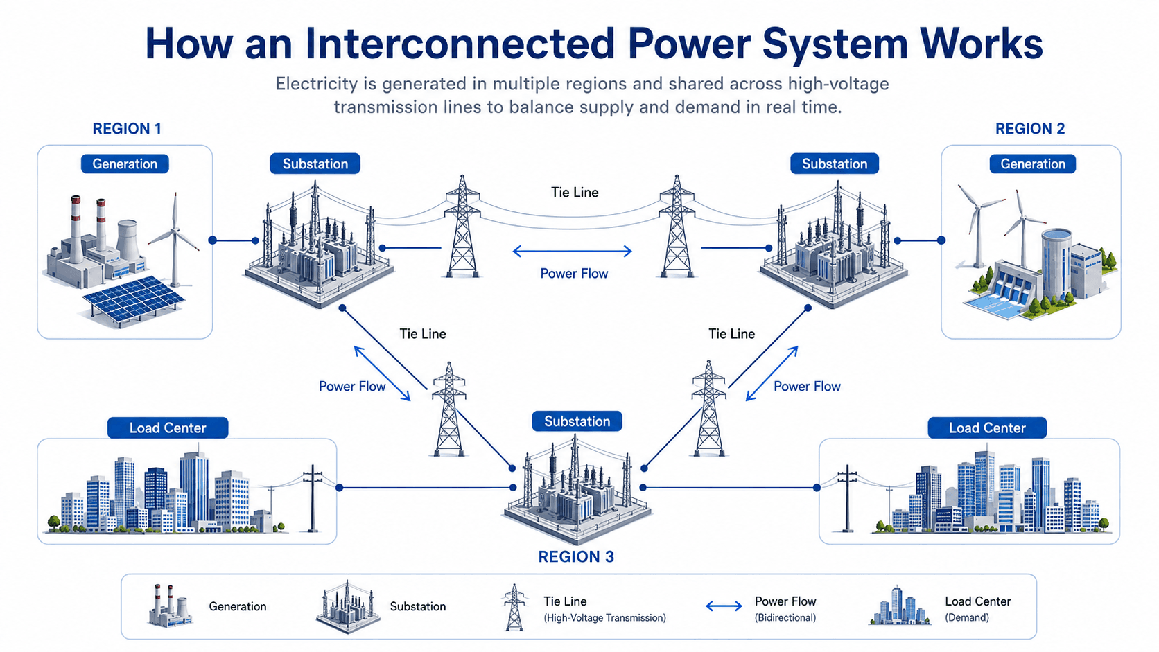
Start by following the tie lines between the regions. The key concept is not just that several generators exist, but that the network creates shared paths for power exchange, reserve support, and system balancing.
What Is an Interconnected Power System?
An interconnected power system is a large electrical network formed by connecting multiple power systems so they operate together. In a typical AC interconnection, generators and load areas are electrically tied through high-voltage transmission lines and operate at a common nominal frequency, such as 60 Hz in much of North America.
The practical engineering idea is that interconnection turns separate supply areas into a shared operating network. A region with surplus generation can support a neighboring region with higher demand, and a generator outage in one area can be partially covered by reserves elsewhere. That flexibility is valuable, but it also means disturbances, overloads, and stability problems must be controlled across a much larger system.
Interconnection is not the same as unlimited transfer capacity. Thermal limits, voltage limits, stability limits, contingency limits, market rules, and operator procedures all determine how much power can actually move between areas.
Main Parts of Interconnected Power Systems
Interconnected power systems combine physical equipment, control systems, and operating rules. The equipment may look familiar from smaller power systems, but the interactions become more important when regions are tied together over long distances.
| Component | Role in an interconnected system | Engineering concern |
|---|---|---|
| Generating stations | Supply real and reactive power from thermal, hydro, nuclear, wind, solar, storage, or other resources. | Generator controls, ramp rate, inertia, fuel availability, dispatch limits, and inverter behavior affect system balance. |
| High-voltage transmission lines | Move bulk power between regions, substations, and major load centers. | Thermal rating, voltage profile, stability limit, right-of-way constraints, and outage conditions limit transfer capability. |
| Tie lines | Connect separate areas or balancing regions so power can be exchanged. | Tie-line flows must be monitored because overloads can trigger protection actions or cascading trips. |
| Substations | Switch circuits, transform voltage, connect lines, and isolate faults. | Breaker ratings, bus configuration, transformer loading, protection zones, and communication schemes affect reliability. |
| Load centers | Represent cities, industrial areas, campuses, data centers, and distribution systems consuming power. | Load growth, power factor, voltage sensitivity, peak demand, and load-shedding priority shape planning decisions. |
| Control and protection systems | Keep frequency, voltage, power flow, and fault response within acceptable limits. | Poor coordination can turn a local equipment event into a wider reliability problem. |
How Power Flows Between Connected Regions
In an AC interconnected system, real power flow is strongly influenced by voltage magnitude, line reactance, and the phase angle difference between connected buses. Operators can schedule generation and manage system conditions, but power does not simply follow one selected route; it distributes through available network paths according to electrical impedance and operating conditions.
This simplified relationship shows why interconnected systems are sensitive to voltage, line reactance, and angle separation. \(P\) is the approximate real power transfer, \(V_1\) and \(V_2\) are the bus voltage magnitudes, \(X\) is the transfer reactance between areas, and \(\delta\) is the voltage angle difference.
Power transfer generally improves when voltage is strong and the transfer path is electrically strong. Transfer capability becomes constrained when the path is weak, heavily loaded, voltage-limited, or operating with a large angle separation.
This expression is mainly useful for intuition. It assumes a highly simplified AC transfer path and is not a substitute for full AC load-flow, short-circuit, voltage stability, transient stability, or protection studies.
Frequency ties the system together
In a synchronized AC interconnection, connected generators rotate in step with the same nominal system frequency. If generation and load become unbalanced, frequency changes across the interconnection. This is why frequency control, reserves, governor response, and automatic generation control are central to interconnected grid operation.
Voltage support is local and regional
Real power can often be transferred long distances, but reactive power and voltage support are more local. Capacitors, reactors, generator excitation, transformer tap changers, static VAR compensators, and synchronous condensers may be needed to maintain acceptable voltage profiles across heavily loaded corridors.
Isolated vs Interconnected Power Systems
The clearest comparison is redundancy. An isolated system may be easier to understand and operate, but it has fewer backup paths. An interconnected system has more sources, shared reserves, and alternate supply routes, but it also requires more coordination.
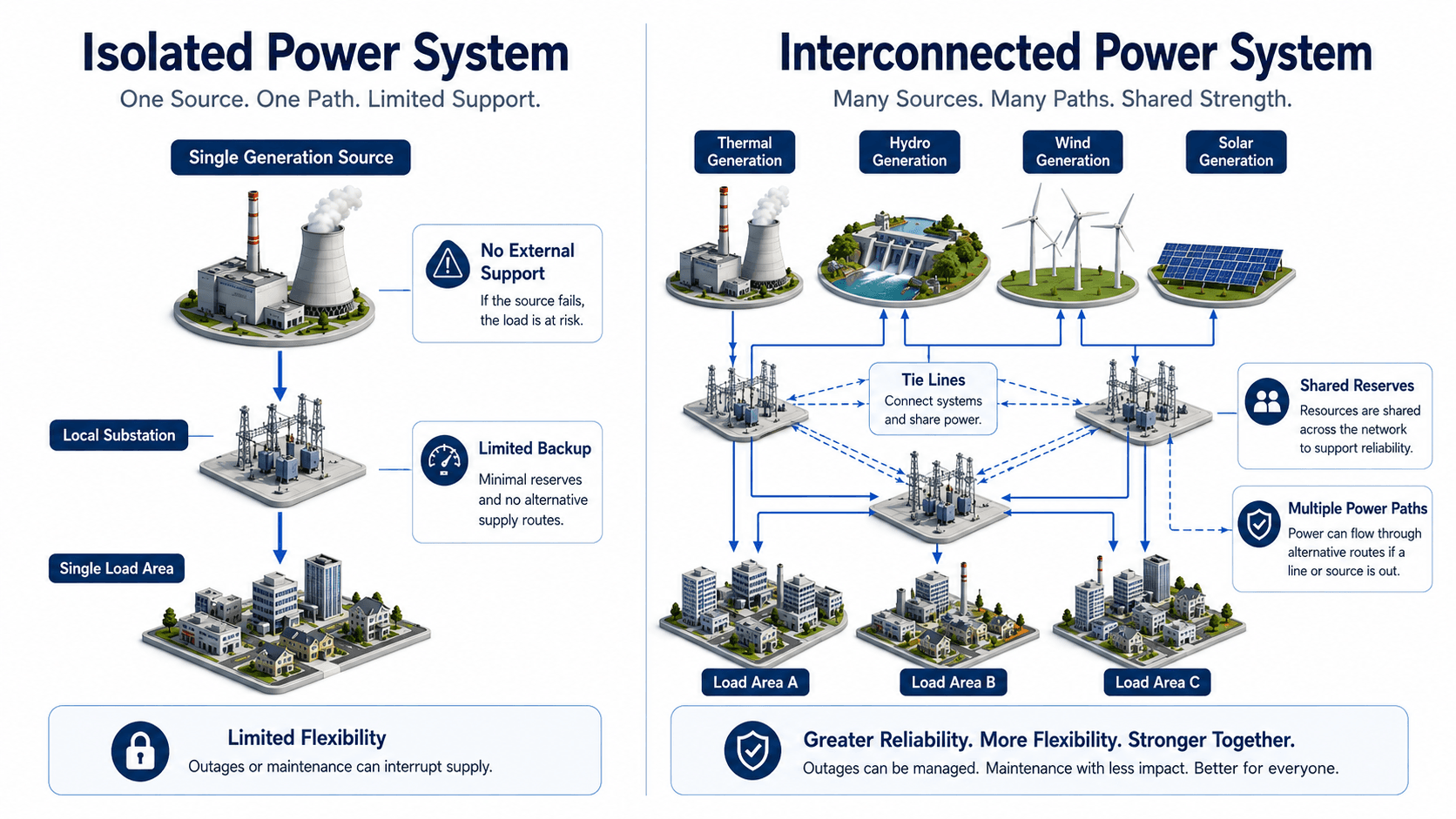
| Comparison point | Isolated power system | Interconnected power system |
|---|---|---|
| Supply support | Depends mostly on local generation and local reserves. | Can receive support from neighboring areas through tie lines or controlled links. |
| Reliability | A local generator or line outage can have a large impact if backup is limited. | Alternate sources and paths can reduce the impact of many single contingencies. |
| Operating complexity | Usually simpler to monitor and operate. | Requires coordination among operators, protection zones, dispatch, reserves, and stability limits. |
| Disturbance behavior | Problems may remain local, but local loads have less outside support. | Problems can be contained with good controls, but severe disturbances can propagate if not managed. |
| Best fit | Remote sites, islands, microgrids, backup systems, and off-grid facilities. | Regional grids, bulk power systems, utility networks, and large power markets. |
Why Utilities Interconnect Power Systems
Interconnection is one of the reasons modern power systems can serve large, changing loads with many different generation resources. The main advantage is not just that more wires exist; it is that the system can coordinate generation, reserves, and transfers over a wider area.
- Reserve sharing: Neighboring systems can support each other during generator outages, load spikes, or unexpected resource shortfalls.
- Economic dispatch: Lower-cost generation can serve load beyond its immediate local area when transmission capacity is available.
- Load diversity: Peaks do not occur everywhere at exactly the same time, so a larger interconnected area can use resources more efficiently.
- Maintenance flexibility: Planned outages on generators or transmission elements can be easier to manage when alternate supply paths exist.
- Renewable integration: Wind, solar, hydro, and storage resources can be balanced over a wider geographic footprint.
- Large-load support: Industrial facilities, electrification, and data center growth can be served more reliably when the grid has multiple supply paths and planning options.
Interconnection value depends on usable transfer capability. A tie line that is frequently congested, voltage-limited, or stability-limited may provide less real operating flexibility than its physical connection suggests.
What Makes an Interconnection Strong or Weak?
A strong interconnection is not defined only by voltage level or line length. It is defined by how much reliable, controllable support it can provide during normal operation, maintenance outages, and credible disturbances.
| Interconnection quality | Strong interconnection | Weak interconnection |
|---|---|---|
| Electrical strength | Low effective transfer impedance and strong voltage support. | High transfer impedance, weak voltage profile, or limited reactive power support. |
| Transfer capability | Can carry scheduled and emergency transfers under normal and contingency conditions. | Quickly constrained by thermal ratings, voltage limits, or stability margins. |
| Redundancy | Has alternate paths so one outage does not remove all support. | Depends on a single corridor, transformer, bus, or critical switching station. |
| Protection performance | Clears faults selectively and quickly without unnecessary loss of healthy equipment. | Has relay coordination gaps, communication limitations, or high risk of misoperation. |
| Operator visibility | Has real-time telemetry, alarms, state estimation, and clear operating procedures. | Operators have limited visibility into actual tie-line loading or post-contingency risk. |
| Dynamic behavior | Damps oscillations and remains stable after credible faults and trips. | Has poor damping, low inertia, weak grid behavior, or unstable post-fault recovery. |
AC Synchronization vs HVDC Tie Lines
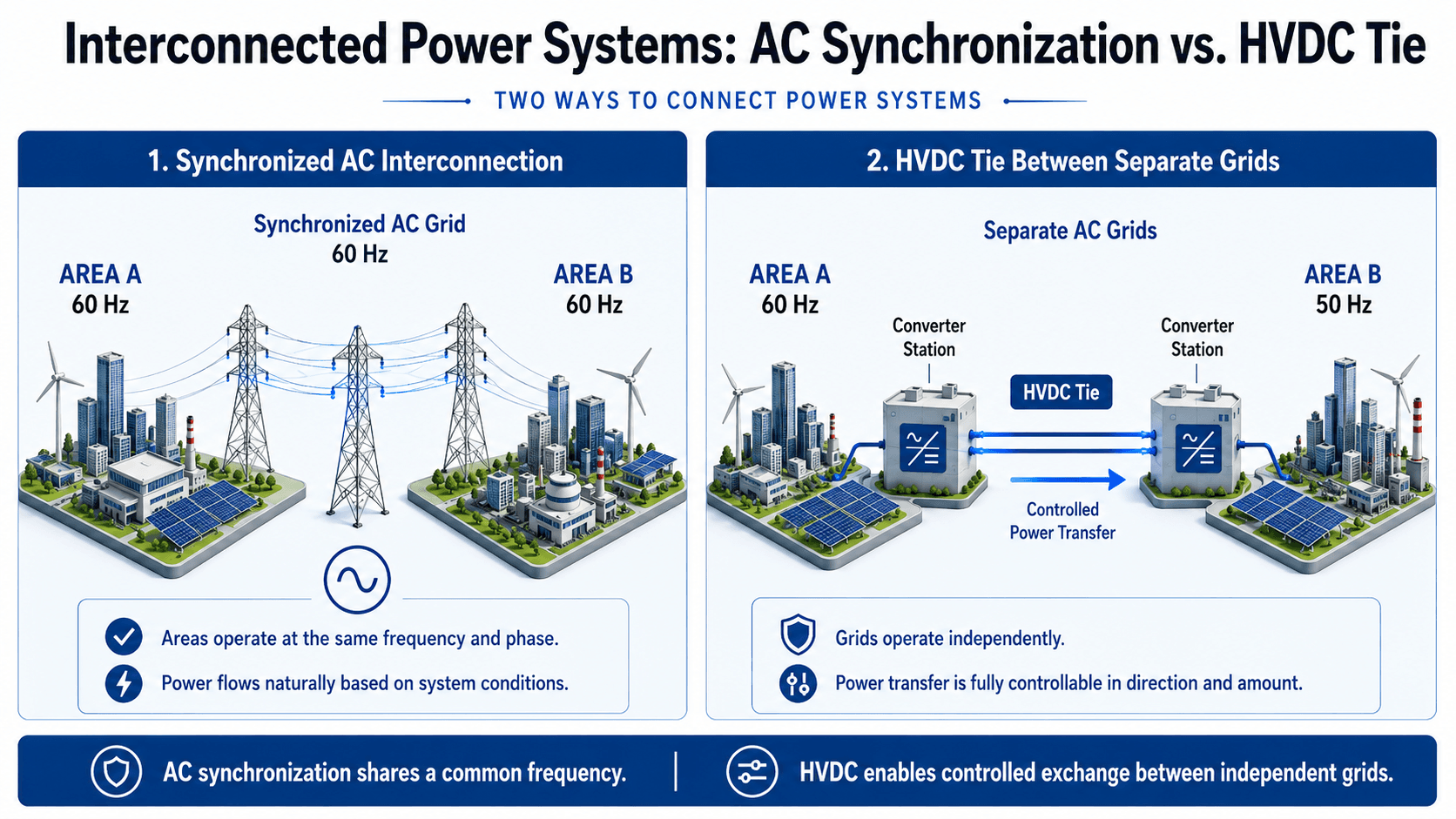
Not every grid connection works the same way. Some power systems are connected as one synchronized AC interconnection. Others exchange power through high-voltage direct current links, which can connect separate AC grids that do not operate in phase with each other.
Synchronized AC interconnection
In a synchronized AC interconnection, generators and connected areas operate at the same nominal frequency and remain electrically tied during normal conditions. Power flows naturally through the network based on impedance, voltage, and phase angle. This allows strong sharing of system support, but it also means dynamic disturbances can affect a broad area.
HVDC ties between separate grids
HVDC links use converter stations to change AC to DC and then back to AC. This allows controlled power transfer between systems that are not synchronized, or between areas where controllability and long-distance transfer are important. HVDC does not remove the need for planning, but it can provide a controlled interface between otherwise independent AC grids.
How Interconnected Power Systems Are Operated
Operating an interconnected power system is a continuous balancing task. Generation and load must be matched in real time, voltage must stay within acceptable ranges, and tie-line schedules must be monitored against actual network flows.
| Operating function | What it does | Why it matters in an interconnection |
|---|---|---|
| Balancing authority coordination | Coordinates generation, load, interchange, and reserves over a defined operating area. | Interconnected regions must support local reliability while respecting scheduled interchange with neighbors. |
| Automatic generation control | Adjusts generator output to help correct frequency and tie-line error. | Small imbalances across a large grid require fast and coordinated response. |
| Scheduled interchange | Defines planned power exchanges between areas. | Actual flows must be monitored because physical power paths may differ from commercial schedules. |
| Operating reserves | Provide capacity that can respond to outages, forecast errors, or sudden load changes. | Shared reserves are one of the major reliability benefits of interconnection. |
| Real-time contingency analysis | Tests whether the system can survive credible outages from its current operating state. | Operators need to know whether the next line, generator, or transformer trip would create overloads or voltage problems. |
Studies Engineers Run Before Relying on an Interconnection
A one-line diagram can show that two systems are connected, but it cannot prove that the interconnection is secure. Engineers use studies to test the grid under normal, outage, and disturbance conditions before depending on the connection for firm support.
Define the transfer objective, model the base case, test normal loading, run contingency cases, check short-circuit duty, evaluate transient and voltage stability, review protection coordination, and document operating limits before using the interconnection as a reliability resource.
| Engineering study | What it checks | Why it matters |
|---|---|---|
| Load-flow study | Bus voltages, MW and MVAR flows, line loading, transformer loading, and losses. | Shows whether the interconnection works under expected steady-state operating conditions. |
| Short-circuit study | Fault current levels, breaker duty, equipment interrupting ratings, and fault contributions. | Interconnection can increase available fault current and require equipment or protection changes. |
| Transient stability study | System response after faults, line trips, generator outages, and major switching events. | Confirms whether generators and areas remain synchronized after severe disturbances. |
| Voltage stability study | Reactive power margin, weak buses, transfer limits, and voltage collapse risk. | Heavy transfers can fail from voltage instability before equipment thermal limits are reached. |
| Relay coordination review | Protection zones, clearing times, communication-assisted schemes, backup protection, and reclosing. | Faults must be isolated selectively without unnecessary trips that weaken the grid. |
| Transfer capability study | Safe transfer levels under normal and post-contingency conditions. | Determines how much power can be moved reliably, not just physically. |
| Power quality and harmonic review | Harmonics, flicker, converter behavior, filtering, and inverter interactions. | Especially important where HVDC terminals or large inverter-based resources connect to the grid. |
Real-World Interconnection Examples
Large power grids are often organized into major interconnections rather than one single global AC grid. Within each synchronized interconnection, utilities and system operators coordinate frequency, transmission planning, reserves, and power transfers.
| Example | What it represents | Why it matters |
|---|---|---|
| Eastern Interconnection | A major synchronized AC grid covering much of eastern North America. | Shows how many utilities and regions can operate electrically tied at a common frequency. |
| Western Interconnection | A major synchronized AC grid covering much of western North America. | Demonstrates regional coordination across long transmission distances and diverse generation resources. |
| Texas Interconnection | A largely separate AC interconnection covering most of Texas. | Illustrates that a region can be internally interconnected while remaining mostly separate from neighboring synchronous grids. |
| HVDC interties | Controlled links between separate AC regions or long-distance resources and loads. | Allow power exchange without forcing the connected AC systems to operate as one synchronized grid. |
These examples are useful because they show that “interconnected” does not always mean the same topology, operating rules, or level of synchronization. The engineering details depend on the physical network, operating authority, transfer capability, and reliability criteria.
Cascading Outages in Interconnected Power Systems
Interconnection improves support between areas, but it can also allow stress to move through the network. A cascading outage begins when one element trips and the remaining system absorbs the flow, voltage, and stability burden. If the system is already near its limits, each additional trip can make the next trip more likely.
| Stage | What happens | Engineering response |
|---|---|---|
| Initial event | A line, generator, transformer, or bus trips because of a fault, overload, or protection action. | Protection must clear the fault selectively while preserving as much healthy equipment as possible. |
| Flow redistribution | Power shifts to remaining paths, increasing loading on other lines and transformers. | Operators and automated tools monitor emergency ratings and post-contingency overloads. |
| Voltage or stability stress | Voltage weakens, angle separation grows, or oscillations develop between areas. | Reactive support, generation redispatch, load shedding, or controlled separation may be required. |
| Additional trips | Relays trip more equipment due to overloads, undervoltage, instability, or protection miscoordination. | Remedial action schemes and emergency procedures attempt to stop the spread. |
| System separation or blackout | The interconnection splits into islands or loses large amounts of load and generation. | Restoration requires staged blackstart, resynchronization, and controlled load pickup. |
Cascading outages are rarely caused by “being interconnected” alone. They usually involve a combination of stressed operating conditions, insufficient situational awareness, protection actions, voltage instability, overloads, and inadequate corrective response.
Senior Engineer Review Checklist for Interconnected Power Systems
A strong interconnected grid is not evaluated only by asking whether two systems are physically connected. Engineers also review whether the connection can be operated securely, protected properly, and supported during credible disturbances.
Start with the intended power exchange, check transfer capability and voltage support, verify stability under contingency conditions, confirm protection coordination, then review operating procedures and monitoring requirements before relying on the interconnection for firm support.
| Review check | What to look for | Why it matters |
|---|---|---|
| Tie-line loading | Normal and emergency ratings, seasonal ratings, and post-contingency flows. | A tie line can exist physically but still be unusable during peak or contingency conditions. |
| Voltage support | Reactive power resources, voltage profiles, transformer taps, and weak-bus behavior. | Inter-area transfers can create voltage problems before thermal limits are reached. |
| Frequency response | Governor response, operating reserves, automatic generation control, and load-shedding schemes. | Frequency stability depends on how quickly the interconnection responds to imbalance. |
| Dynamic stability | Rotor angle stability, damping, inter-area oscillations, and recovery after faults or line trips. | A system can pass steady-state checks but still be vulnerable to dynamic instability. |
| Protection coordination | Relay zones, breaker duty, reclosing logic, communication-assisted schemes, and backup protection. | Misoperation can disconnect healthy equipment or fail to isolate a fault quickly enough. |
| Contingency planning | N-1 and more severe scenarios, remedial action schemes, and controlled separation plans. | Interconnected systems must remain secure after credible outages, not only during normal operation. |
| Operator visibility | Telemetry, state estimation, alarms, and inter-area communication protocols. | Operators need enough real-time information to prevent small issues from becoming system-wide events. |
Engineering Judgment and Field Reality
Textbook diagrams often show clean arrows moving from one area to another, but real interconnected systems are messier. Power flows through parallel paths, load changes continuously, generators have ramp-rate limits, renewable output varies, and protective devices must make decisions in fractions of a second.
Modern grids also include increasing amounts of inverter-based resources, battery storage, flexible loads, data centers, and long-distance renewable transfers. These resources can improve flexibility, but they can also change fault current behavior, inertia, voltage control, ramping needs, and oscillation damping.
The most useful interconnection is not always the one with the highest voltage or longest line. It is the one that provides dependable transfer capability under real operating constraints, including voltage support, protection behavior, maintenance outages, dynamic stability, and contingency limits.
When This Breaks Down
The simplified idea of “many sources feeding many loads” breaks down when the network is stressed beyond its secure operating range. At that point, interconnection can still help, but it can also allow a disturbance to spread if equipment trips, controls saturate, or voltage and frequency move too far from normal values.
- Cascading outages: One line trip shifts power to remaining paths, which may overload and trip in sequence if the system is already stressed.
- Voltage instability: Heavy transfers, weak reactive support, and long transmission distances can cause voltage collapse conditions.
- Frequency excursions: Large generation-load imbalances can move system frequency outside acceptable operating ranges.
- Loss of synchronism: Severe faults, weak damping, or large angle swings can cause generators or areas to separate electrically.
- Protection miscoordination: Incorrect relay settings or communication failures can trip too much equipment or fail to clear faults properly.
- Congestion: Economic power transfers may be limited by physical grid constraints even when generation is available elsewhere.
Common Misconceptions and Practical Checks
Interconnected power systems are often described in simple terms, which can create misleading assumptions. The practical engineering checks below help separate useful simplifications from unsafe conclusions.
| Misconception | Better engineering interpretation | Practical check |
|---|---|---|
| Power follows the shortest path. | Power distributes through available paths based on electrical impedance and system conditions. | Use load-flow analysis to evaluate actual line loading and parallel path flows. |
| More interconnection always means more reliability. | Interconnection improves support only when transfer capability, protection, voltage support, and operating coordination are adequate. | Check contingency performance, not just normal-operation topology. |
| A tie line guarantees emergency support. | A tie line may be constrained by thermal ratings, voltage limits, stability limits, or operating rules. | Review firm transfer limits and emergency operating procedures. |
| Frequency is controlled locally only. | In a synchronized interconnection, frequency reflects the balance of generation and load across the connected system. | Review reserve response and automatic generation control behavior. |
| HVDC is just another transmission line. | HVDC includes converter stations and can control power transfer between separate AC systems. | Evaluate converter limits, controls, losses, harmonics, and AC system strength at each terminal. |
| Distribution interconnection and bulk grid interconnection are the same topic. | Bulk power interconnection deals with regional transmission systems, while distribution interconnection often refers to local DERs such as solar, batteries, and generators on feeders. | Clarify the voltage level, owner requirements, study scope, and point of interconnection before applying guidance. |
Do not evaluate an interconnection only by looking at a one-line diagram. A reliable interconnection requires steady-state checks, dynamic checks, protection review, operating procedures, and contingency analysis.
Engineering References and Design Guidance
Interconnected power systems are planned and operated using utility criteria, reliability standards, transmission studies, and system operator procedures. For a high-level public reference, the U.S. Department of Energy provides a useful overview of major North American interconnections and how synchronized AC grids are electrically tied together.
- U.S. Department of Energy: DOE overview of North American electric interconnections explains major interconnections such as the Eastern, Western, and Texas interconnections and describes their synchronized AC operation.
- Project-specific criteria: Utility interconnection requirements, balancing authority procedures, protection standards, planning criteria, and owner requirements can control the final design and operating approach.
- Engineering use: Planners and operators use these references with load-flow studies, stability models, relay coordination, contingency studies, and real-time operating limits.
Frequently Asked Questions
An interconnected power system is a network where multiple generators, transmission lines, substations, and load areas are electrically tied together so power can be shared between regions. In a synchronized AC interconnection, connected areas operate at the same nominal frequency and must remain stable during normal operation and disturbances.
Power systems are interconnected to improve reliability, share operating reserves, balance load over a larger area, support economic dispatch, and allow power to move from surplus regions to deficit regions. Interconnection also helps integrate diverse resources such as hydro, thermal, wind, solar, storage, and other generation resources.
An isolated power system serves its own load with limited or no support from neighboring systems. An interconnected power system has tie lines or controlled links that allow power exchange, reserve sharing, and alternate supply paths, but it also requires more complex stability, protection, and operating coordination.
Synchronized AC interconnections operate at the same nominal frequency, such as 60 Hz in North America. Separate AC systems can still exchange power without being synchronized if they are connected through HVDC converter stations, which control the magnitude and direction of power transfer.
Interconnected systems can experience cascading outages, voltage instability, frequency excursions, overloaded tie lines, protection miscoordination, congestion, and loss of synchronism. These risks are managed through operating reserves, relay coordination, contingency analysis, stability studies, system monitoring, and controlled separation schemes where appropriate.
Summary and Next Steps
Interconnected power systems connect multiple generation sources, transmission paths, substations, and load centers so power can be exchanged across regions. This improves reliability and operating flexibility, but only when transfer limits, frequency response, voltage support, protection, and contingency planning are handled correctly.
The practical engineering lesson is that interconnection is both a reliability tool and a coordination challenge. After understanding the concept, the next step is learning how load-flow, stability, protection, and transfer capability studies prove whether the interconnection can operate safely under real conditions.
Where to go next
Continue your learning path with related Turn2Engineering resources.
-
Load Flow Analysis
Learn how engineers calculate voltage profiles, line loading, and power flow across interconnected networks.
-
HVDC Systems
Explore how high-voltage direct current links enable controlled power exchange between separate AC systems.
-
Power System Stability
Study rotor angle, voltage, frequency, and dynamic behavior that determine whether interconnected grids remain secure.