Key Takeaways
- Definition: Structural loads are the forces, weights, pressures, and imposed actions a structure must safely carry, transfer, and resist.
- Main types: Common load categories include dead, live, roof live, snow, rain, wind, seismic, soil, fluid, thermal, impact, and construction loads.
- Design focus: Engineers do not only calculate loads; they trace how those loads move through the structure into the foundation.
- Critical judgment: The controlling load case depends on use, location, geometry, material system, code requirements, and serviceability limits.
Table of Contents
Introduction
In brief: Structural loads are the actions a structure must resist, including permanent weight, occupancy, weather, ground motion, pressure, and construction effects.
Who it’s for: Students, designers, and review engineers.
For informational purposes only. See Terms and Conditions.
Understanding structural loads is one of the first steps in structural design because every member, connection, diaphragm, wall, column, beam, slab, and foundation exists to move load safely through a complete load path.
Structural loads infographic
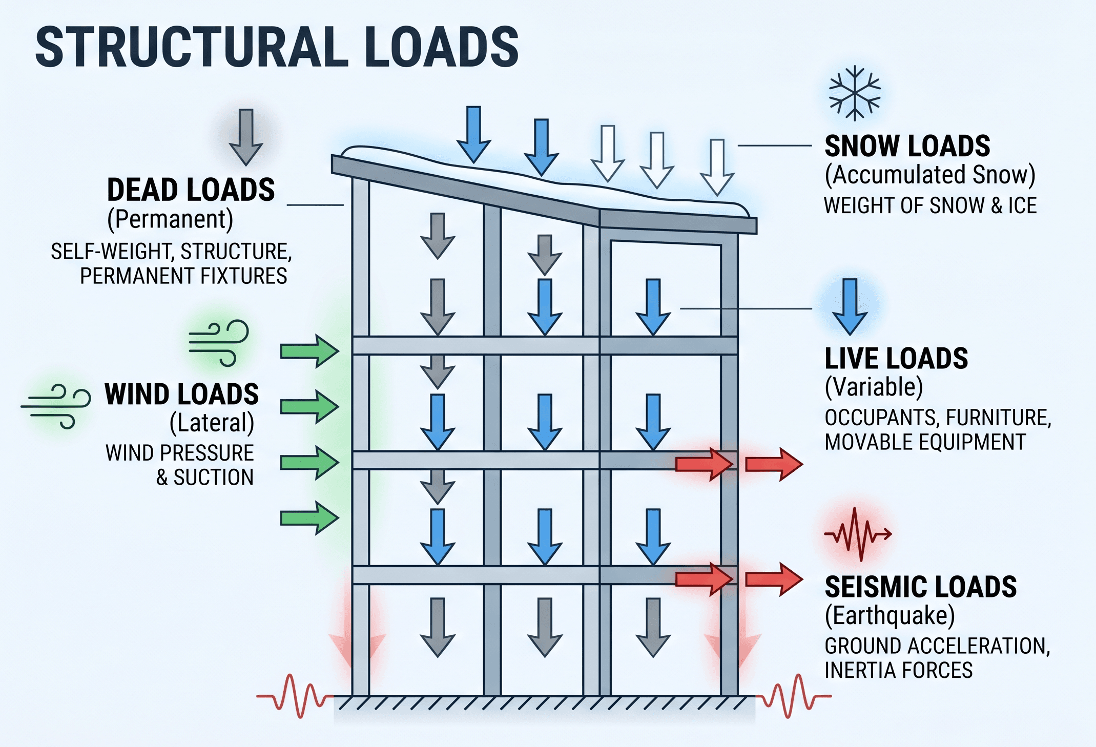
Notice that loads do not act on isolated members only. A roof snow load, floor live load, wind pressure, or seismic inertial force must travel through connected elements before reaching the foundation and supporting ground.
What are structural loads?
Structural loads are the demands placed on a structure by gravity, occupancy, environmental forces, ground movement, retained materials, equipment, temperature changes, construction activities, and accidental events. In design, a load may be expressed as a force, pressure, line load, area load, moment, acceleration, displacement, or imposed deformation.
The purpose of structural engineering is not simply to “hold up weight.” A structure must resist all governing load effects with adequate strength, stability, stiffness, ductility, durability, and serviceability. That means a structural load must be identified, quantified, applied to the correct geometry, distributed through the system, combined with other loads, and checked against acceptable limits.
For example, the weight of a concrete slab may be treated as a dead load, people and furniture may be treated as live load, wind may act as pressure on walls and roofs, and seismic effects may appear as lateral inertial forces caused by ground acceleration. These actions may control different parts of the same building.
Before sizing members, ask: What loads exist, where do they enter the structure, what path do they take, and which element or connection is most likely to control?
Main types of structural loads
Structural loads are usually grouped by source and behavior. Some loads are permanent and predictable, while others vary with occupancy, climate, use, or rare events. The table below summarizes the major load types engineers consider in building and infrastructure design.
| Load type | Typical source | Common units | Design concern |
|---|---|---|---|
| Dead load | Self-weight of structural and fixed nonstructural components | psf, kPa, plf, kN/m | Permanent gravity demand and long-term load path |
| Live load | People, furniture, movable partitions, storage, vehicles, occupancy | psf, kPa, axle load | Variable use and occupancy demand |
| Roof live load | Maintenance access, construction access, temporary roof activity | psf, kPa | Short-term roof service and access loading |
| Snow load | Accumulated snow, drifting, sliding snow, unbalanced roof snow | psf, kPa | Roof strength, ponding, drift zones, unbalanced loading |
| Rain load | Water accumulation due to drainage limitations or blocked drains | psf, kPa | Ponding, roof deflection, secondary drainage |
| Wind load | Wind pressure, suction, uplift, internal pressure, dynamic response | psf, kPa | Lateral resistance, cladding, uplift, drift, overturning |
| Seismic load | Ground motion causing inertial forces in the structure | base shear, story force | Ductility, lateral system behavior, detailing, drift |
| Soil and fluid pressure | Retained earth, groundwater, tanks, pools, flood pressure | psf, kPa, pcf, kN/m³ | Walls, basements, foundations, tanks, uplift |
| Thermal and movement loads | Temperature change, shrinkage, creep, settlement, restraint | strain, displacement, force | Expansion joints, restraint forces, cracking, serviceability |
| Construction load | Temporary shoring, staging, workers, equipment, partially completed systems | psf, point load, equipment load | Incomplete load paths and temporary stability |
These categories often overlap in real projects. A roof, for instance, may need checks for dead load, roof live load, snow, rain, wind uplift, construction loading, drifted snow, and unbalanced load patterns. A retaining wall may need checks for soil pressure, surcharge, hydrostatic pressure, seismic earth pressure, and construction-stage loading.
Dead loads and permanent gravity loads
Dead load is the weight of materials and components that remain in place for most or all of the structure’s life. This includes beams, columns, slabs, walls, roofs, ceilings, cladding, permanent equipment, built-in finishes, fireproofing, and fixed mechanical or electrical systems.
Dead loads are often easier to estimate than environmental loads because material unit weights are relatively predictable. However, errors still occur when designers miss nonstructural items, underestimate topping slabs, ignore façade systems, or fail to update loads after architectural and mechanical changes.
- \( w_D \) Dead load as an area load, commonly in psf or kPa.
- \( \gamma \) Material unit weight, commonly in pcf or kN/m³.
- \( t \) Material thickness, commonly in feet, inches converted to feet, or meters.
For example, normalweight reinforced concrete is often estimated near 150 pcf. A 6-inch slab has a thickness of 0.5 ft, so its approximate self-weight is \(150 \times 0.5 = 75\) psf before adding finishes, ceilings, partitions, or mechanical allowances.
Dead load mistakes often come from coordination gaps, not math errors. Check architectural sections, MEP equipment schedules, façade systems, roof build-ups, and finish assumptions before finalizing gravity loads.
Live loads and occupancy loads
Live load represents variable loads associated with the way a structure is used. People, furniture, storage, movable equipment, vehicles, maintenance activity, and changing occupancy patterns can all contribute to live load. Unlike dead load, live load can move, disappear, concentrate locally, or change over time.
Building codes typically assign minimum live loads based on occupancy or use. A residential bedroom, office, corridor, library stack area, assembly space, parking garage, and mechanical room can all have different required live loads because the expected use and risk differ.
Live loads can control member strength, vibration, deflection, punching shear, connection demand, and local slab behavior. They also influence future flexibility. A structure designed only for light occupancy may not be suitable for file storage, heavy equipment, dense assembly use, or a future change in occupancy.
The design live load is not always the same as the load you see on a normal day. It is a code-based design demand intended to cover reasonable maximum use conditions for the occupancy.
Environmental loads: wind, snow, rain, and seismic effects
Environmental loads are driven by site conditions and hazard levels. A structure in a high-wind coastal area, heavy snow region, high seismic zone, or intense rainfall climate may be controlled by loads that rarely matter in another location. This is why structural load design is inseparable from geography.
Wind loads
Wind loads act as pressure, suction, uplift, and lateral force. They affect the main wind-force-resisting system, components and cladding, roof edges, parapets, canopies, doors, walls, anchors, and foundations. Taller, lighter, more flexible structures may also require attention to drift, acceleration, vibration, and dynamic response.
Snow and rain loads
Snow loads depend on ground snow, roof exposure, thermal conditions, roof slope, drifting, sliding snow, and unbalanced load patterns. Rain loads become critical when water can accumulate faster than it drains, especially on low-slope roofs where deflection may worsen ponding.
Seismic loads
Seismic loading is different from ordinary lateral pressure. Earthquake ground motion shakes the structure, and the mass of the structure develops inertial forces. Good seismic design depends on strength, stiffness, ductility, detailing, load path continuity, and controlled damage mechanisms.
Do not treat environmental loads as generic values copied from another project. Wind, snow, seismic, flood, and rain demands depend heavily on location, exposure, risk category, geometry, and code procedure.
Load path: how structural loads move through a structure
A load path is the route a load follows from where it is applied to where it is finally resisted. For gravity loads, the path may run from slab to beam to girder to column to footing to soil. For lateral loads, the path may run from cladding or diaphragms into collectors, shear walls, braced frames, moment frames, foundations, and surrounding soil.
A structure can have adequate member sizes and still perform poorly if the load path is incomplete. Missing collectors, weak connections, discontinuous diaphragms, soft stories, transfer irregularities, unbraced compression elements, and inadequate foundation tie-downs can all interrupt the intended flow of forces.
Identify the load source → determine the tributary area or force distribution → transfer the load to supporting members → check connections and diaphragms → follow the load into vertical/lateral elements → verify foundation and soil resistance.
Load path thinking also helps engineers avoid isolated checks. A beam reaction is not finished once the beam is designed. That reaction becomes a load on a girder, column, bearing wall, connection, base plate, footing, pile cap, or retaining element. Every reaction has a next step.
Structural load calculations and tributary areas
Many preliminary load calculations begin by converting area loads into line loads or point loads. Floors, roofs, slabs, and decks are often assigned area loads, while beams and walls usually need line loads and columns or foundations often receive concentrated reactions.
- \( W \) Total load over the tributary area, commonly in lb, kip, N, or kN.
- \( q \) Uniform area load, commonly in psf or kPa.
- \( A \) Tributary area assigned to the member or support.
In this expression, \(w\) is the line load on a beam and \(b_t\) is the tributary width. For example, if a floor load is 100 psf and a beam supports a 12 ft tributary width, the approximate uniform line load on the beam is \(100 \times 12 = 1200\) plf, before considering load factors or additional member self-weight.
Worked example
Suppose an office floor beam supports a 10 ft tributary width. The floor system has 65 psf of dead load and 50 psf of live load. The service-level line dead load is \(65 \times 10 = 650\) plf, and the service-level line live load is \(50 \times 10 = 500\) plf. The beam therefore carries 1,150 plf before adding the beam self-weight or applying strength-level load combinations.
This simple example shows why tributary areas matter. A change in framing direction, beam spacing, slab span, cantilever length, wall location, or supported area can change the load assigned to a member even when the area load value stays the same.
Load combinations and controlling design cases
Structures rarely experience one load at a time. A roof may experience dead load, snow load, wind uplift, rain load, and construction load during different stages or combinations. A building may experience dead load, live load, wind, and seismic effects in separate code-required cases. Load combinations provide a structured way to evaluate credible simultaneous demands.
Design methods usually distinguish between strength and serviceability. Strength checks ask whether members and connections can resist required factored demands. Serviceability checks ask whether deflection, drift, vibration, cracking, ponding, or movement remain acceptable under expected service-level conditions.
| Design question | Possible controlling load | What the engineer checks |
|---|---|---|
| Will a floor beam have enough flexural strength? | Dead plus live load | Moment, shear, bearing, lateral bracing, connection reaction |
| Will a tall building move too much? | Wind load | Story drift, acceleration, cladding movement, occupant comfort |
| Will a roof fail near a height change? | Drifted snow load | Local roof framing, deck, connections, ponding risk |
| Will a lateral system perform during an earthquake? | Seismic load | Base shear, drift, ductile detailing, collectors, foundations |
| Will a basement wall resist lateral pressure? | Soil and hydrostatic pressure | Bending, shear, sliding, overturning, drainage assumptions |
The controlling case is not always obvious at the start. An efficient design process checks the expected controlling cases early, then confirms that secondary cases do not govern hidden details such as uplift anchors, diaphragm collectors, vibration limits, connection eccentricities, or construction-stage stability.
Engineering judgment and field reality
Structural loads are often presented as clean numbers, but actual projects involve imperfect information. Drawings change, equipment weights arrive late, rooftop units move, wall types change, openings are added, snow drifts around screens, contractors stage materials in concentrated piles, and owners change how spaces are used.
Experienced engineers therefore combine code-based load values with judgment about likely future use, constructability, uncertainty, redundancy, and consequences of failure. A lightly loaded office floor may still need special checks if it contains compact storage, heavy safes, movable partitions, file rooms, dense assembly areas, or mechanical equipment.
Temporary construction loading can be more dangerous than final service loading because the complete load path may not exist yet. Shoring, sequencing, bracing, storage, crane picks, and partial composite action require careful review.
Field judgment is also important for existing structures. When evaluating an older building, the original design loads may not match current code requirements, current use, deterioration, modifications, or hidden construction details. Load evaluation may require drawings, field investigation, testing, material assumptions, and conservative engineering interpretation.
When structural load assumptions break down
Structural load assumptions break down when the real structure or real use differs from the design model. This can happen because of inaccurate geometry, missed components, uncoordinated equipment, changed occupancy, blocked drainage, unusual wind exposure, construction sequencing, deterioration, or incorrect assumptions about how loads are shared.
Common breakdown conditions include concentrated loads applied to members designed for uniform load, rooftop equipment installed without review, heavy storage placed in office areas, water ponding on flexible roofs, snow drifting against taller walls, added façade systems, removed walls or braces, and tenant improvements that alter the load path.
Assumptions also break down when stiffness distribution differs from the model. A diaphragm may not distribute lateral load as expected, a transfer beam may attract more load than assumed, a cracked concrete section may deflect more than predicted, or a flexible support may change reaction distribution between adjacent members.
Do not assume that a load is safe because it is “temporary.” Short-duration loads can still exceed local capacity, especially when concentrated on slabs, decks, roofs, or partially completed framing.
Common pitfalls and engineering checks
Good load design requires more than selecting values from a table. Engineers must check whether the chosen load is appropriate for the actual use, whether the load is applied correctly, and whether the load path remains continuous under all relevant design cases.
- Mixing service-level loads with factored strength-level loads in the same calculation.
- Forgetting member self-weight when sizing beams, girders, slabs, and foundations.
- Using uniform loads when a concentrated load or wheel load controls local behavior.
- Ignoring unbalanced snow, drifted snow, wind uplift, or rain ponding on roofs.
- Checking members but not checking connections, collectors, anchors, bearing, or foundations.
- Using live load values without verifying occupancy, storage, assembly use, or future flexibility.
- Assuming a complete load path during construction before the permanent system is fully connected.
| Check | Why it matters | Typical question |
|---|---|---|
| Tributary area | Controls how area loads become member loads | Is the correct floor, roof, or wall area assigned? |
| Load path | Prevents discontinuities and hidden weak points | Can the load reach the foundation safely? |
| Load combination | Captures credible simultaneous load effects | Which strength and service cases govern? |
| Local effects | Uniform loads may miss concentrated reactions | Are wheels, posts, equipment legs, or bearing points checked? |
| Serviceability | Strength alone does not control performance | Are deflection, drift, vibration, cracking, and ponding acceptable? |
Relevant standards and design references
Structural load requirements are governed by building codes, referenced standards, material codes, and project-specific criteria. The exact standards depend on the jurisdiction, structure type, material system, and design scope.
- ASCE 7: Commonly used in the United States for minimum design loads and associated criteria for buildings and other structures, including dead, live, wind, snow, rain, flood, ice, and seismic provisions.
- International Building Code: Establishes adopted building requirements in many jurisdictions and references structural loading standards, risk categories, occupancy rules, and material design provisions.
- AISC, ACI, NDS, and TMS standards: Material-specific design references that use structural load effects to check steel, concrete, wood, and masonry members and connections.
- Project and owner criteria: Industrial facilities, equipment platforms, bridges, energy sites, data centers, and special structures may require loads beyond minimum building-code values.
Always verify the governing code edition, local amendments, risk category, occupancy classification, site hazards, and owner requirements before applying load values to final design.
Frequently asked questions
Structural loads are the forces, weights, pressures, and imposed actions that a structure must resist and transfer safely. They include gravity loads, occupancy loads, environmental loads, soil and fluid pressures, thermal effects, and temporary construction loads.
Dead load is the permanent or mostly permanent weight of the structure and fixed components. Live load is variable and comes from people, furniture, vehicles, storage, movable equipment, occupancy, and other changeable use conditions.
Load combinations help engineers evaluate realistic cases where multiple loads may act together. They are used to check strength, stability, uplift, overturning, drift, deflection, and serviceability under required design scenarios.
The controlling load depends on the structural system, location, use, geometry, material, and limit state being checked. Gravity loads may control beams, wind may control drift and uplift, seismic loads may control lateral detailing, and snow or rain may control roof framing.
A load path is the route a load follows from the point where it is applied through members, connections, diaphragms, walls, frames, foundations, and ultimately into the supporting ground.
Summary and next steps
Structural loads are the demands that define how a structure must perform. Dead load, live load, wind, snow, rain, seismic effects, soil pressure, fluid pressure, thermal movement, equipment loads, and construction loads all influence member sizing, connection design, serviceability, stability, and foundation demand.
The most important design habit is to think in load paths. A load is not fully handled until it has moved from its source through every required member, connection, diaphragm, lateral element, support, foundation, and soil interface. This is why structural load design is both a calculation process and an engineering judgment process.
For real projects, always verify code requirements, occupancy, site hazards, owner criteria, temporary conditions, and future use assumptions. The load that controls one part of a structure may not control another.
Where to go next
Continue your structural engineering learning path with these related resources.
-
Study structural analysis
Learn how engineers convert structural loads into reactions, shear, moment, axial force, deflection, and member demand.
-
Learn load path analysis
Follow how gravity and lateral loads travel through structural systems into supports and foundations.
-
Review wind design
Explore one of the most important environmental load cases for buildings, towers, roofs, cladding, and lateral systems.