Key Takeaways
- Core idea: Transformer protection detects electrical, thermal, pressure, gas, and insulation-related problems before a transformer failure damages equipment or spreads through the power system.
- Engineering use: Engineers combine differential, restricted earth fault, overcurrent, Buchholz, pressure, thermal, lockout, and breaker failure protection so credible fault types have dependable detection paths.
- What controls it: Transformer size, winding connection, grounding, CT location, CT ratio, inrush behavior, fault current, breaker arrangement, and oil system design shape the final protection scheme.
- Practical check: A transformer protection review should verify the protected zone, CT polarity, relay compensation, breaker trip logic, alarm versus trip actions, backup coordination, and commissioning tests together.
Table of Contents
Introduction
Transformer protection is the coordinated use of relays, current transformers, mechanical sensors, thermal devices, and circuit breakers to detect transformer faults and isolate the affected equipment. A strong protection scheme does more than trip quickly; it separates internal faults from external system events, limits damage, and keeps healthy parts of the power system energized.
Transformer Protection Scheme Diagram
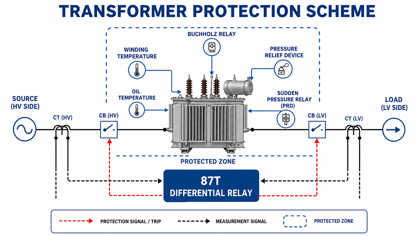
Read the diagram from the transformer outward: the dashed boundary defines the protected zone, CT inputs feed the differential relay, and relay trip outputs open the breakers that isolate the transformer.
What Is Transformer Protection?
Transformer protection is the protection philosophy and device arrangement used to detect abnormal conditions in transformers. It includes electrical protection functions such as differential, restricted earth fault, overcurrent, ground fault, breaker failure, and lockout logic, plus mechanical and thermal devices such as Buchholz relays, sudden pressure relays, pressure relief devices, oil temperature indicators, and winding temperature indicators.
The important idea is that a transformer is protected by layers. A winding-to-ground fault, a high-current through fault, an internal arcing event, slow overheating, and gas accumulation in oil do not look the same to the protection system. A good scheme assigns each fault type to a device that can detect it dependably and trip, alarm, or back up another device at the correct time.
Transformer protection is not one relay. It is a coordinated protection zone with primary protection, backup protection, mechanical protection, thermal protection, alarms, breaker trip paths, lockout logic, and maintenance review points.
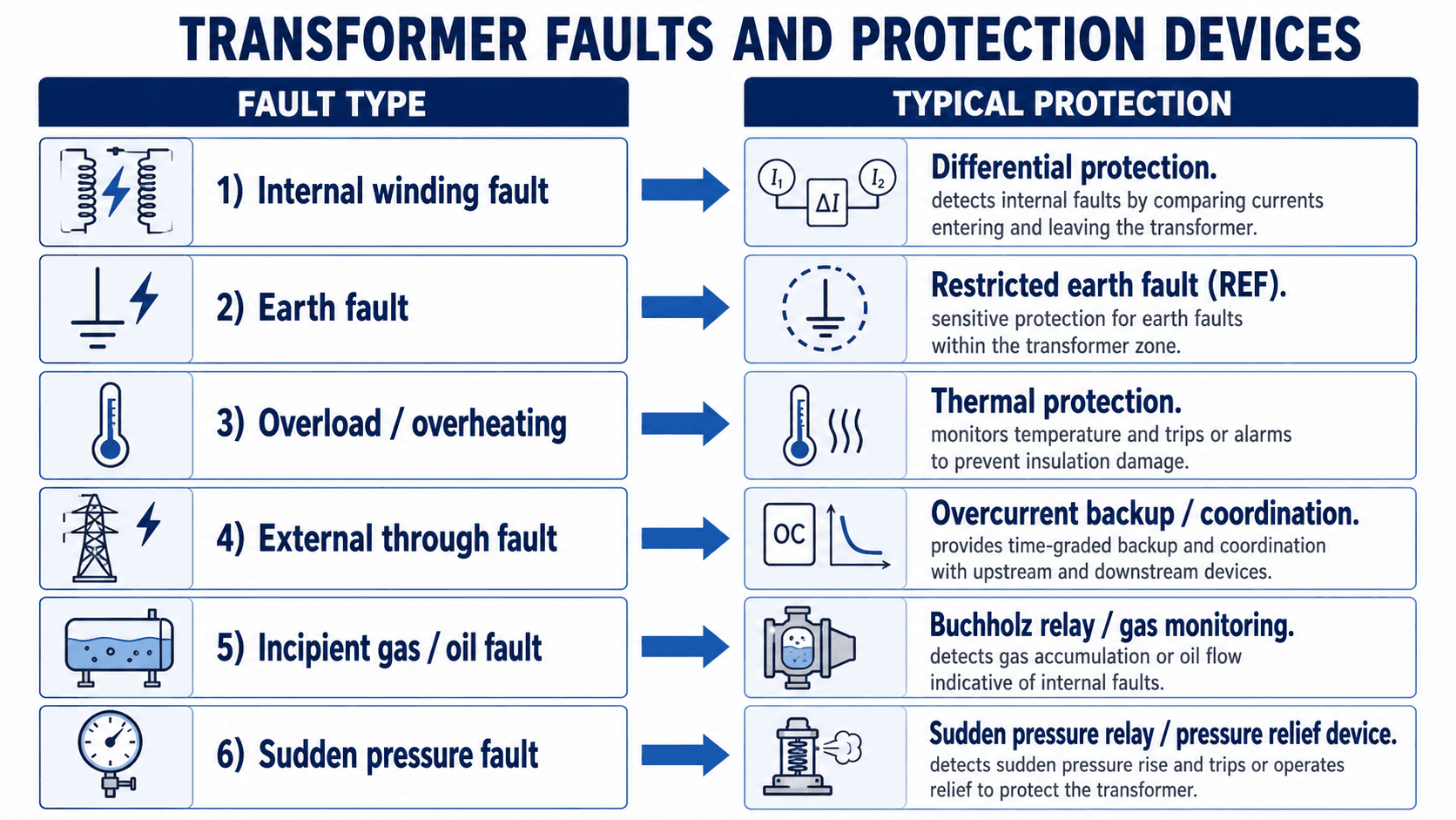
Transformer Faults and Protection Devices
Transformer protection starts by identifying the fault type. Internal winding faults need fast selective isolation, earth faults need sensitive ground-fault detection, overloads need thermal supervision, external through faults need stable backup coordination, and oil-filled transformer problems may appear first as gas, pressure, or temperature changes.
| Fault or condition | Typical protection | Trip or alarm behavior |
|---|---|---|
| Internal winding fault | Transformer differential protection, usually identified as 87T | Fast trip of transformer breakers for faults inside the CT-defined zone. |
| Winding-to-ground fault | Restricted earth fault, ground differential, or ground overcurrent depending on transformer grounding | Sensitive trip for ground faults that may not produce very high phase current. |
| Overload or overheating | Winding temperature, oil temperature, thermal model, and overload supervision | Alarm, load reduction, staged cooling, or trip depending on severity and operating philosophy. |
| External through fault | Overcurrent protection, breaker failure, and coordinated upstream/downstream relays | Usually time-delayed backup so the nearest protective device clears first. |
| Gas formation in oil | Buchholz relay, gas relay, or dissolved gas monitoring depending on transformer type | Alarm for slow gas accumulation and trip for severe oil surge conditions where applicable. |
| Sudden internal pressure rise | Sudden pressure relay and pressure relief device | Trip, pressure relief operation, or alarm depending on device design and project settings. |
How Transformer Protection Works
Transformer protection works by defining a protected zone, measuring electrical quantities at the zone boundaries, monitoring physical transformer conditions, and sending a trip command when the detected condition matches a credible transformer fault. The protection zone is usually bounded by current transformers and circuit breakers, but physical devices on the transformer add another layer of coverage.
Protected zones and circuit breakers
A protected zone is the portion of the power system a relay is responsible for isolating. For a transformer differential scheme, the zone is typically the transformer and its terminal equipment between the high-side and low-side CTs. If the fault is inside that zone, the relay should trip the associated breakers. If the fault is outside the zone, the relay should remain secure while other protection clears the fault.
Electrical protection versus mechanical protection
Electrical protection responds to current, voltage, frequency, or sequence quantities. Mechanical and thermal transformer protection responds to gas, oil movement, pressure, oil temperature, winding temperature, oil level, and cooling system conditions. This distinction matters because some developing transformer failures produce gas or heat before they create a high-current electrical fault.
Alarm functions versus trip functions
Not every transformer protection device should immediately trip the transformer. Gas accumulation, high oil temperature, fan failure, low oil level, or abnormal dissolved gas may first be alarm conditions. Severe internal faults, rapid pressure rise, high differential current, or critical temperature conditions may require automatic tripping. A strong design clearly separates alarms, trips, lockouts, and operator response.
Primary, Backup, Mechanical, and Thermal Protection
A transformer protection scheme should be understood as a layered system. Primary protection isolates serious transformer faults quickly. Backup protection clears faults if the primary system or breaker does not operate. Mechanical and thermal protection catch failure modes that may not immediately appear as high electrical current.
| Protection layer | Typical functions | Role in transformer protection |
|---|---|---|
| Primary electrical protection | 87T differential, restricted earth fault, ground differential | Trips quickly for internal transformer faults inside the protected zone. |
| Backup electrical protection | Phase overcurrent, ground overcurrent, breaker failure, upstream backup | Clears faults when primary protection or the intended breaker does not clear the fault. |
| Mechanical protection | Buchholz relay, sudden pressure relay, pressure relief device, oil level alarm | Detects gas, oil surge, pressure rise, or physical transformer abnormality. |
| Thermal protection | Winding temperature, oil temperature, thermal overload model, cooling system alarms | Protects insulation life and warns operators before overheating becomes a failure. |
| Trip logic and lockout | Trip matrix, 86 lockout, breaker trip coils, DC control power supervision | Ensures the correct breakers open and serious transformer trips are not accidentally reclosed. |
Primary and backup protection are not interchangeable. Differential protection may identify an internal transformer fault in cycles, while backup overcurrent protection may wait for coordination time so downstream or adjacent protection can operate first.
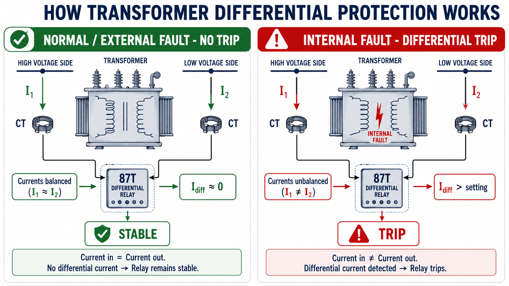
Transformer Differential Protection
Transformer differential protection compares compensated current entering and leaving the transformer protection zone. During normal load or an external through fault, the relay should see balanced current after CT ratio, polarity, phase shift, tap, and transformer connection compensation are applied. During an internal fault, the current balance is lost and the 87T element operates.
In this simplified expression, the relay is not comparing raw primary currents. It is comparing compensated current quantities after CT ratio correction, polarity, phase angle shift, transformer vector group, tap position, and zero-sequence treatment are considered. That is why transformer differential protection settings require the transformer data and CT data, not just load current.
- 87T ANSI-style device function commonly used for transformer differential protection.
- CT Current transformer that provides scaled current measurements to the relay from the protection-zone boundaries.
- Idiff Differential current used by the relay to decide whether the transformer zone contains an internal fault.
- Restraint Relay logic that improves stability during load, through faults, CT saturation, and transformer energization.
Why restraint and inrush logic matter
A transformer can draw high magnetizing inrush current when energized, and external faults can create high through-current that may saturate CTs. The relay must trip dependably for real internal faults while remaining secure for inrush, external faults, CT mismatch, tap position changes, and normal transformer loading.
Transformer Protection Relay Functions
Many transformer protection schemes are described by relay function numbers and common protection names. These labels help engineers review one-lines, relay settings, trip matrices, and test plans without relying on a long written description every time.
| Function | Common label | What it protects against | Typical role |
|---|---|---|---|
| Transformer differential | 87T | Internal transformer phase faults, winding faults, lead faults, and some bushing-zone faults inside the CT boundary | Primary fast protection |
| Restricted earth fault | REF / 64REF | Sensitive winding-to-ground faults within a restricted transformer zone | Primary sensitive ground fault protection |
| Phase overcurrent | 50 / 51 | High phase current from faults or overload conditions depending on settings | Backup or primary for smaller transformers |
| Ground overcurrent | 50G / 51G or 50N / 51N | Ground faults detected through residual, neutral, or ground-current measurement | Ground fault protection or backup |
| Thermal overload | 49 | Winding and insulation heating caused by loading, ambient temperature, or cooling limitations | Alarm, load management, or trip |
| Gas or sudden pressure | 63 / 63P | Gas accumulation, oil surge, or rapid internal pressure rise in oil-filled transformers | Mechanical alarm or trip |
| Lockout relay | 86 | Maintained lockout after serious transformer trips | Trip logic and reclose prevention |
| Breaker failure | 50BF | Failure of a breaker to interrupt after a trip command | Backup tripping of adjacent breakers or upstream sources |
Relay functions should be reviewed against the actual transformer, CTs, breaker arrangement, trip coils, DC control power, lockout logic, and owner operating philosophy. A function number alone does not prove that the protection zone is correct.
Major Transformer Protection Methods
A complete transformer protection scheme usually includes fast primary protection, sensitive ground fault protection, time-coordinated backup protection, and physical monitoring devices. The exact combination depends on transformer MVA, voltage class, winding arrangement, grounding, owner requirements, fault duty, and whether the transformer is oil-filled, dry-type, sealed, or conservator-type.
Differential protection
Differential protection is often the main protection for medium and large power transformers because it is fast and selective for internal faults. It is especially useful when high fault energy could quickly damage windings, bushings, tap changers, leads, and tank components.
Restricted earth fault protection
Restricted earth fault protection provides sensitive ground fault detection within a defined transformer zone. It can detect winding-to-ground faults that may be too low in magnitude for phase overcurrent protection to detect quickly, especially when grounding impedance limits fault current.
Overcurrent backup protection
Overcurrent protection is usually backup protection for larger transformers. It responds to excessive current but does not inherently know whether a fault is inside the transformer, on the bus, on a feeder, or downstream in the system. That is why time-current coordination and selectivity matter.
Buchholz relay and gas monitoring
A Buchholz relay is used on conservator-type oil-filled transformers and is typically installed in the pipe between the main tank and the conservator. Slow gas accumulation is commonly treated as an alarm condition, while a severe oil surge can initiate a trip. Buchholz protection does not apply to every transformer design, especially dry-type, sealed, or non-conservator transformers.
Temperature, pressure, and relief devices
Temperature and pressure devices protect against conditions that may not immediately appear as an electrical fault. Winding temperature, oil temperature, sudden pressure, pressure relief, cooling failure, and oil level alarms help operators respond before insulation aging, tank damage, or catastrophic failure occurs.
Small vs Large Transformer Protection
Transformer protection is scaled to asset value, fault energy, system importance, and operating consequence. A small distribution transformer may use relatively simple overcurrent or fuse protection, while a large substation transformer typically requires a much more complete relay, monitoring, and trip system.
| Transformer application | Typical protection approach | Why the scheme changes |
|---|---|---|
| Small distribution transformer | Fuses, current-limiting fuses, upstream overcurrent, and basic surge/grounding protection | Lower equipment cost and simpler system role often make simple protection acceptable. |
| Medium facility transformer | Phase/ground overcurrent, temperature alarms, pressure devices, and sometimes differential or REF | The consequence of an outage or internal failure may justify more selective protection. |
| Large power transformer | 87T differential, REF, overcurrent backup, Buchholz, sudden pressure, temperature, lockout, and breaker failure | High asset value and high fault energy require fast, selective, and layered protection. |
| Critical generator step-up or substation transformer | Redundant differential, independent trip paths, monitoring, DGA integration, breaker failure, and detailed alarm response | System reliability and outage consequence justify redundancy and more formal protection review. |
What Controls the Transformer Protection Scheme?
Transformer protection is shaped by the transformer, the power system around it, and the owner’s protection philosophy. Two transformers with the same MVA rating may still require different settings and devices if their grounding, vector group, breaker arrangement, CT locations, or duty cycle are different.
| Protection factor | Why it matters | Engineering implication |
|---|---|---|
| Transformer MVA and voltage class | Larger and higher-voltage transformers usually justify faster, more selective, and more redundant protection. | Differential, REF, pressure, gas, and temperature protection become more important as equipment value and fault energy increase. |
| Winding connection and vector group | Delta-wye and other transformer connections can shift current phase angles between sides. | The differential relay must compensate for ratio and phase shift so normal load does not appear as an internal fault. |
| Grounding method | Solid grounding, resistance grounding, reactance grounding, or ungrounded systems produce different ground fault currents. | Ground fault and REF protection must be selected so it is sensitive enough without tripping for external faults. |
| CT location, ratio, polarity, and class | The relay can only compare the currents it receives from the CTs. | Wrong polarity, poor CT matching, or CT saturation can cause false trips or failure to trip. |
| Transformer inrush behavior | Energizing a transformer can create high magnetizing current that is not an internal fault. | Differential protection often uses harmonic restraint, inrush blocking, or secure operating characteristics. |
| Available fault current | Short-circuit analysis defines expected fault current and equipment duty. | Relay pickup, coordination, CT performance, breaker duty, and arc energy all depend on realistic fault current values. |
| Breaker and trip circuit arrangement | The relay must trip the correct devices to isolate the transformer from all energizing sources. | Switchgear, trip coils, lockout relays, and DC control power must be reviewed with the protection scheme. |
| Oil/conservator design | Some mechanical devices apply only to certain oil-filled transformer designs. | Buchholz relay logic should not be assumed for sealed, dry-type, or non-conservator transformers. |
Transformer protection settings should be developed from transformer MVA, impedance, voltage, vector group, tap range, CT ratio/class/burden, grounding, inrush behavior, through-fault current, breaker clearing time, relay restraint settings, and coordination requirements.
Transformer Protection Review Checklist
Use this checklist as a practical review path when evaluating a transformer protection concept, one-line diagram, relay scheme, or design package. The goal is not to calculate every setting from a table; it is to verify that the scheme detects credible faults, remains secure for non-fault events, and trips the correct breakers.
Identify the transformer type, MVA, voltage, winding connection, and grounding. Define the protection zones and breaker boundaries. Select primary protection, backup protection, mechanical protection, and thermal protection. Review CTs, compensation, restraint, trip/alarm logic, coordination, and commissioning tests.
| Review check | What to look for | Why it matters |
|---|---|---|
| Define the protected zone | Confirm the CTs, breakers, transformer terminals, bushings, and leads included in the zone. | A differential relay protects only the zone it can measure. A drawing error can leave equipment unprotected or cause unwanted trips. |
| Verify CT polarity and ratio | Check CT orientation, ratio selection, wiring, relay inputs, and terminal markings. | Incorrect CT polarity or ratio is one of the most serious causes of differential protection misoperation. |
| Confirm transformer compensation | Review vector group, tap range, zero-sequence treatment, and relay compensation settings. | The relay must compare equivalent currents after transformer phase shift and ratio differences are considered. |
| Check inrush security | Review energization logic, harmonic restraint, blocking, and expected magnetizing inrush behavior. | Transformer energization should not look like an internal fault to the differential element. |
| Map mechanical devices | Identify Buchholz, sudden pressure, pressure relief, oil temperature, winding temperature, oil level, and cooling alarms. | Some developing transformer failures are first detected by gas, temperature, or pressure rather than current. |
| Review trip matrix | Confirm which breakers trip for 87T, REF, Buchholz trip, pressure trip, lockout, and backup protection. | The relay decision is only useful if the correct interrupting devices isolate every source feeding the transformer. |
| Coordinate backup protection | Check time-current coordination with upstream and downstream relays, fuses, and breakers. | Backup protection should clear faults when primary protection fails without unnecessarily tripping too much of the system. |
| Plan commissioning tests | Include CT checks, relay injection tests, functional trip tests, alarm tests, and end-to-end logic checks. | Protection depends on field wiring and device behavior, not only on settings in a relay file. |
Trip Matrix: Alarm, Trip, and Lockout Logic
A transformer protection design should identify what each protection event actually does. Some conditions should alarm first, some should trip immediately, and some should initiate lockout logic so the transformer cannot be re-energized until the cause is investigated.
| Condition | Typical action | Engineering reason |
|---|---|---|
| 87T differential trip | Trip transformer breakers and often initiate lockout | Indicates a likely internal transformer fault inside the protected zone. |
| REF trip | Trip transformer breakers and often initiate lockout | Indicates a sensitive internal ground fault in the transformer winding zone. |
| Buchholz gas alarm | Alarm and investigate | Slow gas accumulation may indicate developing insulation or oil problems. |
| Buchholz surge trip | Trip or lockout depending on protection philosophy | Rapid oil movement may indicate a severe internal fault. |
| High oil or winding temperature | Alarm, cooling response, load reduction, or trip | Thermal stress accelerates insulation aging and may lead to failure. |
| Sudden pressure | Trip, alarm, or pressure relief operation depending on device and design | Rapid pressure rise can indicate arcing or a severe internal fault. |
| Breaker failure | Trip adjacent breakers or upstream sources | If the intended breaker does not clear, backup tripping is needed to isolate the fault. |
Engineering Judgment and Field Reality
The textbook explanation of transformer protection often focuses on current comparison, but real transformer protection is influenced by construction details, relay settings, CT performance, breaker arrangements, maintenance practices, and operating philosophy. A transformer may be electrically healthy but thermally stressed, mechanically abnormal, or showing gas trends that justify investigation.
- Through faults can be severe even outside the transformer zone. External faults may not be internal transformer faults, but they can still impose high mechanical and thermal stress on transformer windings.
- Cooling system problems can become protection problems. Fan failure, pump failure, blocked radiators, high ambient temperature, and loading cycles can push insulation aging even without a short circuit.
- Alarm response matters. Gas, temperature, oil level, and pressure alarms are only useful if operating procedures treat them as actionable conditions rather than nuisance indications.
- Event records tell the story. Relay oscillography, sequence of events, breaker status, alarm history, and transformer monitoring data should be reviewed together after a trip.
Do not judge a transformer trip from the relay target alone. Review the one-line diagram, CT circuits, transformer nameplate, breaker trip matrix, event records, temperature history, gas or pressure alarms, and recent switching activity together.
When Transformer Protection Breaks Down
Transformer protection breaks down when the protection system no longer represents the real transformer, the real power system, or the real field wiring. Most poor outcomes come from a mismatch between the scheme assumption and the installed equipment.
- CT saturation during external faults: High through-current can distort CT output and create apparent differential current if restraint and CT selection are inadequate.
- Incorrect CT polarity or wiring: A reversed CT can make normal load current look like internal fault current.
- Unmodeled transformer phase shift: Delta-wye transformers and tap settings require correct relay compensation.
- Inrush treated as a fault: Energization current can be large and asymmetrical, so transformer differential relays need secure inrush logic.
- Mechanical protection ignored: A transformer can develop gas, pressure, or temperature problems before electrical relays see a high-current fault.
- Backup coordination not reviewed: Poor time-current coordination can trip upstream equipment unnecessarily or fail to clear a downstream fault promptly.
Transformer protection does not prevent every transformer failure. It detects abnormal conditions and isolates equipment after thresholds are met, but it does not replace insulation testing, oil testing, dissolved gas analysis, cooling system inspection, thermal loading review, maintenance, or proper transformer specification.
Common Mistakes and Practical Checks
The most common transformer protection mistakes come from treating the relay setting file as the whole protection system. Settings matter, but the full scheme includes CTs, breaker trip circuits, alarms, lockout logic, control power, mechanical devices, maintenance tests, and operating procedures.
| Common mistake | Why it is a problem | Practical check |
|---|---|---|
| Assuming overcurrent protection is enough | Overcurrent relays may be too slow or not selective enough for internal transformer faults. | Review whether differential, REF, gas, pressure, and thermal protection are justified by transformer size and criticality. |
| Ignoring transformer inrush | Energization current can create apparent differential current. | Confirm inrush restraint or blocking logic and review energization event records. |
| Reviewing CTs only by ratio | Ratio alone does not prove polarity, class, burden, saturation performance, or wiring are correct. | Check CT polarity, wiring diagrams, test reports, relay inputs, and expected secondary current direction. |
| Treating Buchholz as universal | Buchholz relays apply to conservator-type oil-filled transformers, not every transformer design. | Confirm transformer oil system type before specifying gas relay logic. |
| Not separating alarms and trips | Alarm-only conditions may be ignored, while trip conditions must be decisive and tested. | Build a clear alarm/trip matrix for gas, oil level, temperature, pressure, differential, REF, and backup events. |
| Forgetting breaker failure and backup logic | A relay trip command does not clear the fault if the breaker or trip circuit fails. | Review breaker failure initiation, lockout relay behavior, DC control power, and backup tripping paths. |
Do not copy transformer protection settings from another transformer without reviewing the transformer nameplate, grounding, vector group, CTs, breaker arrangement, system fault levels, and owner protection philosophy.
Engineering References and Design Guidance
Transformer protection is an engineering application topic, so final relay selection, settings, alarms, and trip logic normally depend on utility standards, owner criteria, equipment manuals, relay manuals, CT data, transformer test reports, and commissioning procedures.
- IEEE C37.91: IEEE guide for protecting power transformers provides recognized guidance for power transformer protection philosophy, relay applications, and protection considerations.
- Project-specific criteria: Owner standards, utility interconnection requirements, transformer specifications, relay manufacturer manuals, and protection philosophy documents often control the final scheme.
- Engineering use: Use references to support the design review, then verify the installed scheme through CT testing, relay testing, trip checks, alarm checks, control circuit checks, and operating procedure review.
Frequently Asked Questions
Transformer protection is the use of relays, current transformers, sensors, mechanical devices, and circuit breakers to detect transformer faults and isolate the transformer before damage spreads. A complete scheme normally combines fast electrical protection with thermal, pressure, gas, and backup protection.
For many medium and large power transformers, differential protection is the primary fast protection because it detects internal faults inside the CT-defined transformer zone. It is usually supported by restricted earth fault, overcurrent backup, Buchholz, sudden pressure, pressure relief, temperature protection, breaker failure, and lockout logic.
Differential protection compares compensated current entering and leaving the transformer zone to detect internal faults quickly and selectively. Overcurrent protection responds to excessive current and is usually used as backup because it may not distinguish between transformer internal faults and faults elsewhere on the system.
Transformer differential protection needs restraint because normal energization, magnetizing inrush, external through-faults, CT saturation, tap position, and phase shift can create apparent differential current. Restraint logic helps the relay trip for real internal faults while staying stable for non-internal events.
Overcurrent protection may be acceptable for some smaller or less critical transformers, but it is usually not enough by itself for larger power transformers. Overcurrent relays are typically backup protection because they cannot identify internal transformer faults as selectively as differential, REF, gas, pressure, and thermal devices.
A Buchholz relay detects gas accumulation or oil movement associated with internal problems in conservator-type oil-filled transformers. It can provide an alarm for slow gas buildup and a trip for severe oil surge conditions, but it is not used on every transformer design.
Summary and Next Steps
Transformer protection protects one of the most important and expensive assets in a power system by combining electrical relays, CTs, breakers, mechanical devices, thermal monitoring, alarms, lockout logic, and backup protection. The scheme must detect internal faults quickly while staying secure for normal load, inrush, and external through faults.
The most useful protection review starts with the protected zone and works outward: verify CTs, breaker trip paths, transformer compensation, ground fault sensitivity, gas and pressure devices, temperature alarms, backup coordination, trip matrix behavior, and commissioning tests. A relay setting file is only one part of the complete transformer protection system.
Where to go next
Continue your learning path with related Turn2Engineering power systems resources.
-
Protective Relays
Learn how relays detect abnormal power system conditions and initiate breaker trips.
-
Differential Protection
Review the current-comparison method behind transformer, bus, generator, motor, and line differential schemes.
-
Short-Circuit Analysis
See how fault current calculations support relay settings, equipment duty checks, and protection coordination.