Key Takeaways
- Core idea: Coupling design connects two rotating shafts so torque can pass from a driver to a driven machine without creating avoidable vibration, bearing load, or service problems.
- Engineering use: Engineers use coupling design for motor-pump sets, gearboxes, conveyors, fans, crushers, test stands, servo axes, and other rotating equipment.
- What controls it: The main drivers are torque, speed, service factor, shaft diameter, bore fit, misalignment, backlash, stiffness, environment, and maintenance access.
- Practical check: A coupling that is strong enough in torque can still be wrong if it ignores alignment, thermal growth, starting torque, balance, or installation clearance.
Table of Contents
Introduction
Coupling design is where shaft alignment, torque transmission, vibration control, and serviceability meet. A coupling connects two rotating shafts, but the design decision affects far more than torque capacity: it can change bearing loads, backlash, machine vibration, maintenance access, installation tolerance, and drivetrain reliability.
Coupling Design Workflow
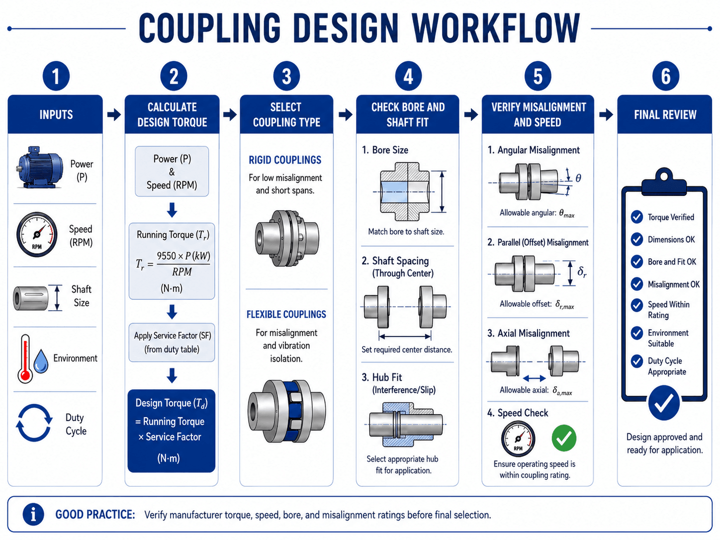
Notice that the workflow does not stop after torque is calculated. The coupling must also fit the shafts, tolerate the expected misalignment, stay within speed limits, and remain maintainable after the machine is installed.
What Is Coupling Design?
Coupling design is the part of mechanical design that deals with connecting a driving shaft to a driven shaft. The coupling may connect a motor to a pump, a gearbox to a conveyor, a servo motor to a ball screw, or a turbine to a compressor. Its basic job is simple: transmit torque. Its actual design role is broader: manage the interaction between two rotating machines.
A coupling is often treated as a catalog item, but the design decision affects shaft loads, bearing life, vibration, installation tolerance, service access, backlash, and machine uptime. A rigid coupling may be correct for a short, accurately aligned assembly. A flexible coupling may be better when small mounting errors, shock loads, or thermal growth are expected. A high-speed coupling may need balance and runout attention that would not matter in a slow conveyor drive.
| What controls coupling selection? | Why it matters |
|---|---|
| Torque | Determines the minimum strength rating and whether service factor or peak torque controls the design. |
| Speed | Affects balance, vibration, runout sensitivity, and manufacturer RPM limits. |
| Misalignment | Controls whether a rigid, flexible, spacer, disc, jaw, gear, Oldham, or other coupling style is appropriate. |
| Backlash and stiffness | Critical for servo systems, positioning equipment, indexing drives, and torsional response. |
| Environment | Controls elastomer choice, corrosion resistance, lubrication needs, temperature limits, and washdown suitability. |
| Maintenance access | Determines whether a spacer, split element, removable guard, or service-friendly hub arrangement is needed. |
The correct coupling is not always the strongest coupling. It is the coupling that safely transmits the required torque at the required speed while matching the alignment, stiffness, damping, backlash, environment, and maintenance needs of the machine.
Coupling Design Inputs Engineers Need First
Coupling selection should start with the system, not the catalog. The designer needs to know what is driving the machine, what is being driven, how the torque varies, how accurately the shafts can be aligned, and how the coupling will be installed and maintained.
| Design input | Why it matters | Engineering implication |
|---|---|---|
| Power and speed | Power and RPM determine the running torque that the coupling must transmit. | Low speed often means higher torque for the same power, which can drive hub size and coupling type. |
| Service factor | Starts, stops, reversing loads, shock, and jams can exceed steady running torque. | The selected coupling must be checked against design torque, not just ideal running torque. |
| Shaft diameter and bore | The coupling hub must physically fit both shafts without exceeding allowable bore limits. | A coupling may have enough torque rating but still fail selection because the shaft bore is too large for that frame size. |
| Keyway, clamp, spline, or set screw | The shaft-to-hub connection determines how torque actually enters the coupling. | Small keys, loose setscrews, poor clamp length, or damaged shaft surfaces can become the weak link. |
| Distance between shaft ends | DBSE, BSE, hub gap, and spacer length control how the coupling is assembled. | Incorrect spacing can preload a flexible element, reduce hub engagement, or make maintenance removal difficult. |
| Misalignment | Real machines have angular, parallel, and axial alignment errors. | The selected coupling must tolerate expected misalignment without creating excessive bearing load or element wear. |
| Speed and balance | At higher RPM, unbalance and runout can become a major vibration source. | High-speed couplings may require tighter machining, better balance, controlled runout, and manufacturer review. |
| Environment | Heat, chemicals, washdown, dust, outdoor exposure, and corrosion can affect coupling materials. | Elastomers, lubrication, seals, coatings, and hub materials must match the operating environment. |
| Maintenance access and guarding | Some couplings need lubrication, element replacement, inspection, and safe guarding. | The design must leave room to remove guards, access bolts, replace elements, and service the machine safely. |
Common Coupling Types and Where They Fit
Coupling type selection is a tradeoff between torque capacity, misalignment tolerance, torsional stiffness, damping, backlash, speed, cost, and maintenance. The same motor power can lead to different coupling choices depending on whether the machine is a precision servo axis, a pump, a crusher, or a conveyor.
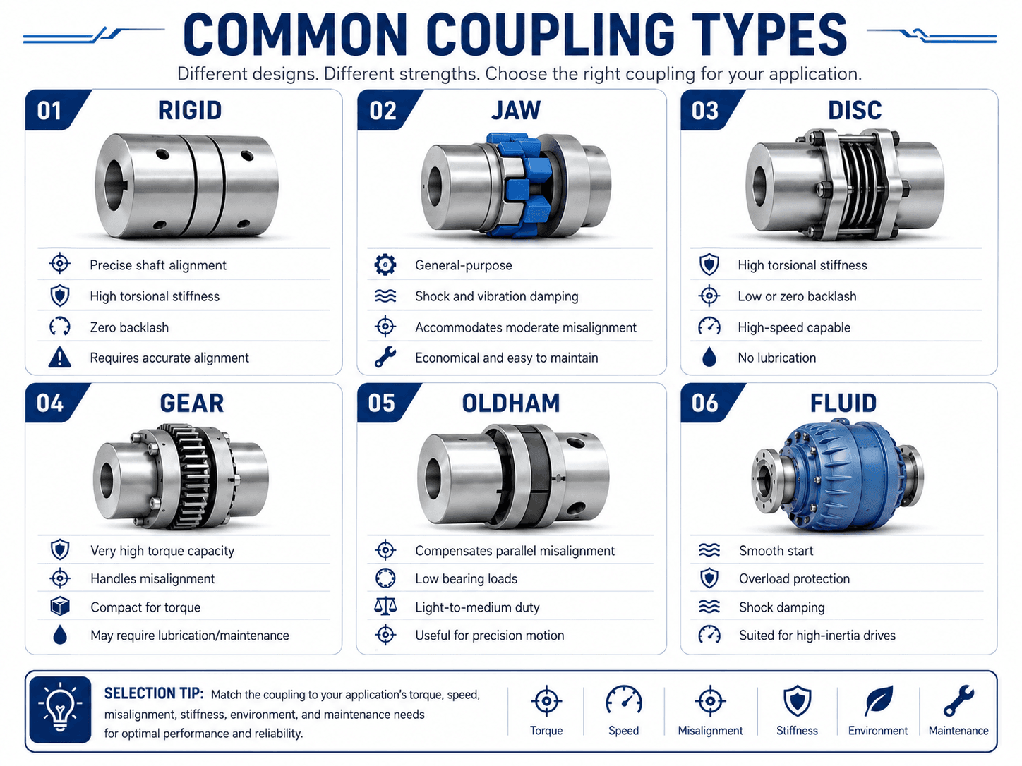
| Coupling type | Best fit | Main caution |
|---|---|---|
| Rigid coupling | Short spans, accurately aligned shafts, high torsional stiffness, low backlash. | Use only when shafts can be aligned accurately and the machine structure maintains that alignment during operation. |
| Jaw coupling | General-purpose motor drives where moderate damping and easy maintenance are useful. | Elastomer selection matters for temperature, chemical exposure, torque, and stiffness. |
| Disc coupling | High-speed or precision equipment needing low backlash and no lubrication. | Disc packs must not be overloaded by misalignment or axial movement beyond rating. |
| Gear coupling | High-torque industrial machinery where compact torque capacity is important. | Lubrication, wear, alignment, and maintenance practices strongly affect life. |
| Oldham coupling | Light-to-medium duty precision motion with parallel offset between shafts. | Not ideal for heavy shock or high torque industrial service. |
| Fluid coupling | High-inertia starts, soft starting, and overload cushioning. | Slip, heat generation, and efficiency must be understood before using it as a simple shaft connector. |
| Spacer coupling | Motor-pump sets and equipment where seal, bearing, or element maintenance is needed without moving major machines. | Spacer length, shaft separation, guard design, and removal path must be checked before final layout. |
Spacer couplings and pump maintenance
Spacer couplings are common in pump and process equipment because they can allow access to seals, bearings, or coupling elements without moving the motor or pump. The design value is not only torque transfer; it is maintainability. The layout should confirm distance between shaft ends, spacer removal length, guard clearance, bolt access, and whether field technicians can service the equipment without disturbing alignment.
How to Select a Coupling by Application
Application context often determines the correct coupling family faster than a generic type list. Start with what the machine actually does: smooth continuous rotation, precision positioning, shock loading, high-inertia starting, high-speed operation, or frequent maintenance.
| Application | Common coupling choices | Why this choice is often used |
|---|---|---|
| Motor to centrifugal pump | Jaw, grid, disc, or spacer coupling | Balances moderate misalignment tolerance, serviceability, vibration control, and pump maintenance access. |
| Servo motor to ball screw | Disc, bellows, beam, or other low-backlash flexible coupling | Controls backlash and torsional windup so positioning accuracy is not lost in the coupling. |
| Conveyor drive | Jaw, grid, gear, or elastomeric coupling | Handles start-stop loading, moderate shock, practical alignment variation, and maintenance needs. |
| Crusher, mill, or heavy industrial drive | Gear, grid, or fluid coupling | High torque, shock loading, overload events, and rugged service usually control the selection. |
| High-speed rotating equipment | Disc, diaphragm, or precision flexible coupling | Speed, balance, runout, stiffness, and controlled misalignment become more important than simple torque rating. |
| Light-duty precision offset drive | Oldham coupling | Parallel shaft offset can be accommodated with relatively low bearing load in light-to-medium duty service. |
| High-inertia start | Fluid coupling or other soft-start arrangement | Reduces shock during acceleration and can provide overload cushioning when properly specified. |
If two coupling types both satisfy torque and bore requirements, compare the application-specific factors next: backlash for positioning systems, damping for shock-loaded drives, lubrication for gear couplings, spacer access for pumps, and balance for high-speed machinery.
Coupling Design Calculations
Coupling calculations normally begin with running torque, then apply a service factor or peak torque requirement. This gives a design torque for comparing against manufacturer ratings. The calculation is not the whole design, but it is the first filter that prevents obvious undersizing.
In SI units, \(T_r\) is running torque in N·m, \(P\) is power in kW, and \(n\) is rotational speed in RPM. For US customary units, a common horsepower relationship is \(T = 5252HP/RPM\), with torque in lb-ft. If you need a quick check, Turn2Engineering also provides a torque calculator, horsepower calculator, and RPM calculator.
Here, \(T_d\) is design torque and \(SF\) is the service factor. The service factor accounts for how gentle or severe the application is. A smoothly loaded fan may require a lower factor than a crusher, indexing drive, reciprocating machine, or conveyor that sees shock, jams, frequent starts, or reversing torque.
- \(T_r\) Running torque under steady operating power and speed.
- \(T_d\) Design torque after service factor, peak torque, or application severity is considered.
- \(P\) Input power, commonly in kW or horsepower.
- \(n\) Operating speed in RPM; for the same power, lower speed creates higher torque.
- \(SF\) Service factor selected from application severity, duty cycle, shock loading, and manufacturer guidance.
Running torque, design torque, peak torque, and fatigue torque
A #1-level coupling selection does not treat every torque value as the same thing. Running torque may describe normal operation, while peak torque may control during startup, braking, jamming, or reversing. Cyclic applications may also require fatigue review.
| Torque term | What it means | When it may control coupling design |
|---|---|---|
| Running torque | Torque required during normal steady operation. | Smooth continuous drives with relatively stable load. |
| Design torque | Running torque multiplied by a service factor or application factor. | General preliminary selection for most motor-driven machines. |
| Peak torque | Highest short-duration torque from start, stop, jam, brake, or reversing event. | High-inertia drives, indexing systems, crushers, conveyors, and reversing machinery. |
| Fatigue torque | Repeated torque range that can damage coupling elements over many cycles. | Reciprocating, cyclic, reversing, or pulse-loaded machinery. |
Worked torque example
Suppose a 15 kW motor drives a pump at 1,750 RPM. The running torque is \(T_r = 9550(15)/1750 = 81.9\) N·m. If the application uses a service factor of 1.5, the design torque becomes \(T_d = 81.9 \times 1.5 = 122.9\) N·m. A coupling selected for this system should exceed that design torque while also satisfying bore size, speed, misalignment, environment, and hub connection requirements.
Do not select a coupling from torque alone. A coupling with adequate torque capacity can still be unsuitable if the bore is too large, the speed rating is too low, the misalignment rating is exceeded, or the hub connection is not appropriate for the shaft.
Misalignment in Coupling Design
Misalignment is one of the biggest reasons coupling designs perform differently in the field than they do on paper. Flexible couplings can tolerate limited misalignment, but that does not mean poor alignment is harmless. Misalignment can increase heat, vibration, bearing load, seal wear, and fatigue in coupling elements.
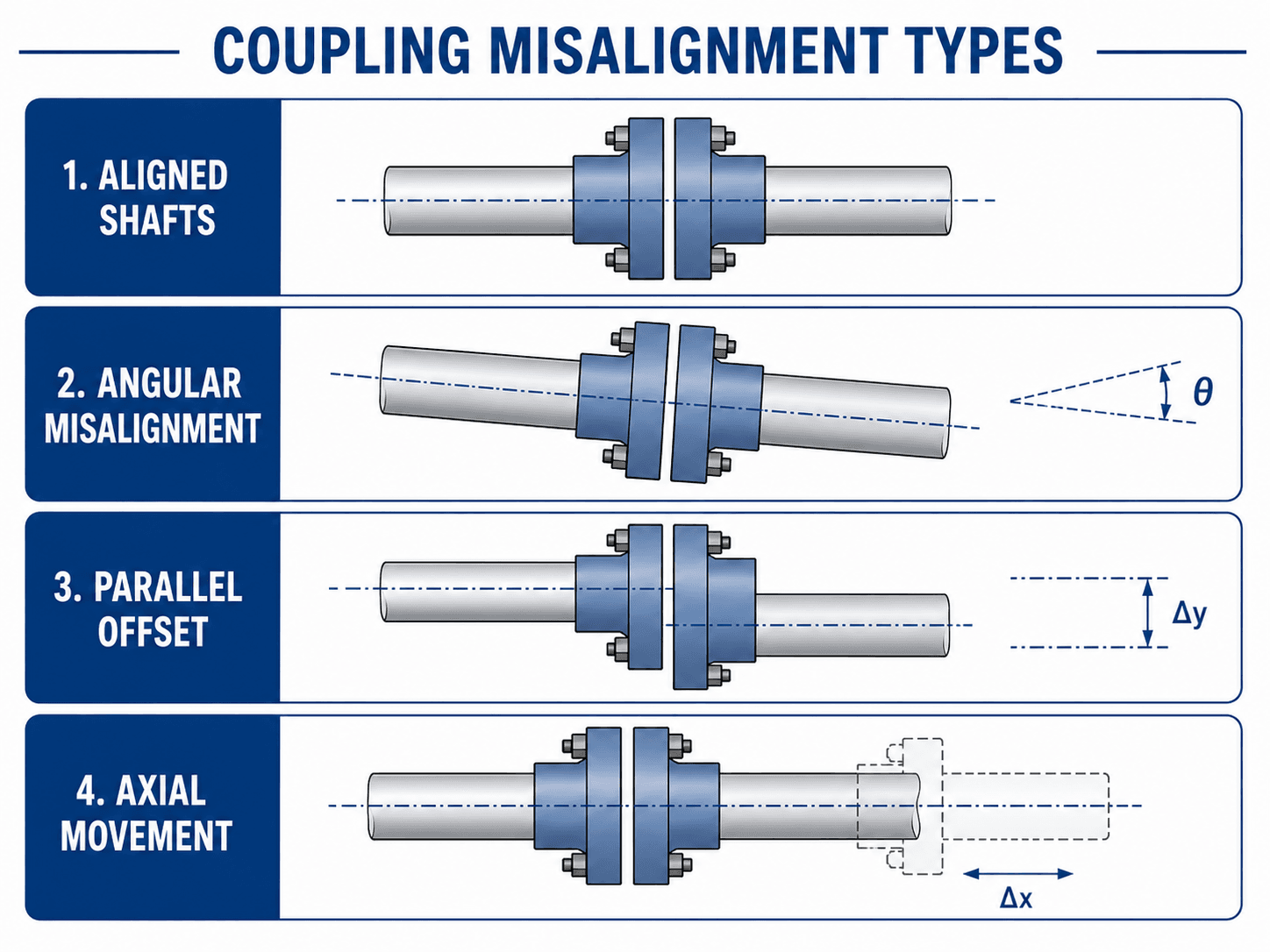
Angular misalignment
Angular misalignment occurs when the shaft centerlines intersect at an angle. It often comes from poor mounting, baseplate distortion, soft foot, or thermal movement. Flexible elements may accommodate some angular error, but the designer should still specify realistic alignment practices.
Parallel offset
Parallel offset occurs when the shafts are parallel but not on the same centerline. It is common when mounting features, shaft heights, or machine bases are not controlled tightly. Offset misalignment can create cyclic loading in flexible elements and connected bearings.
Axial movement
Axial movement occurs when shaft ends move closer together or farther apart along the shaft axis. Thermal growth, bearing float, assembly tolerance, and end thrust can all affect axial position. The coupling must allow the required movement or the machine must control it elsewhere.
Combined misalignment
In real equipment, angular, parallel, and axial misalignment are often present at the same time. A coupling that can tolerate a listed angular misalignment and a listed offset misalignment separately may not tolerate both at their maximum values simultaneously. Final checks should use the manufacturer’s combined misalignment guidance for the specific coupling series.
Rigid vs Flexible Coupling Design Tradeoffs
The rigid-versus-flexible decision is one of the first coupling design choices. Rigid couplings are not “better” because they are stiff, and flexible couplings are not “better” because they forgive small errors. Each option changes how the drivetrain behaves.
| Design question | Rigid coupling implication | Flexible coupling implication |
|---|---|---|
| How accurate is alignment? | Requires very accurate shaft alignment and stable mounting. | Can tolerate limited misalignment, depending on type and rating. |
| Is backlash acceptable? | Typically low or zero backlash if the connection is tight. | Some types are low-backlash; elastomeric types may have windup or compliance. |
| Is shock damping needed? | Transmits shock directly through the drivetrain. | Elastomeric or fluid types can reduce shock and vibration transfer. |
| Is torsional stiffness critical? | High stiffness supports precise motion and phase relationship. | Stiffness varies widely; disc and bellows types differ from jaw or tire types. |
| What happens if alignment drifts? | Bearings and shafts may see added load quickly. | The coupling may absorb some error, but life can still drop sharply if ratings are exceeded. |
For precision motion, backlash and torsional stiffness may control the selection. For a pump skid, misalignment, serviceability, and element replacement may be more important. For heavy industrial drives, torque density, lubrication, and maintenance planning may dominate.
Shaft Spacing, DBSE, Hub Fit, and Guard Clearance
Coupling drawings may use terms such as distance between shaft ends, DBSE, BSE, hub gap, shaft separation, or spacer length. These dimensions control whether the coupling element is preloaded, whether hubs fully engage the shafts, and whether the assembly can be removed for maintenance.
Hub fit is just as important as coupling type. A keyed hub, clamping hub, taper-lock hub, spline, or set-screw hub changes how torque enters the coupling. A poor hub fit can cause fretting, slip, shaft damage, eccentricity, and vibration even when the coupling rating looks acceptable.
Coupling guards should be considered during layout, not after selection. The coupling outside diameter, spacer length, bolt heads, lubrication access, and removal path all affect guarding and maintenance access. A design that cannot be safely inspected or serviced is not complete.
Before release, verify bore depth, hub engagement, shaft end gap, fastener access, guard clearance, and whether the coupling element or spacer can be removed without moving major equipment.
Senior Engineer Coupling Design Review Checklist
A good coupling review checks the complete drivetrain. Use this checklist after a preliminary coupling has been selected and before the design is released, purchased, or installed.
Start with running torque and service factor, then verify bore capacity, hub connection, shaft spacing, speed rating, misalignment ratings, environment, guard clearance, and maintenance access. If any one of those checks fails, the coupling selection is not complete.
| Review check | What to look for | Why it matters |
|---|---|---|
| Design torque | Rated torque exceeds running torque multiplied by service factor, or exceeds the required peak torque case. | Prevents obvious undersizing under real duty instead of ideal steady-state operation. |
| Maximum bore | Both shaft diameters fit within the selected coupling size without weakening the hub. | A torque-capable coupling can still be unusable if the required bore is too large. |
| Hub connection | Key, clamp, spline, taper lock, or set screw method is suitable for torque, direction changes, and service conditions. | The shaft-to-hub interface often controls slip, fretting, and field reliability. |
| DBSE and shaft spacing | Distance between shaft ends, hub length, spacer length, and installation gap match manufacturer requirements. | Incorrect spacing can preload flexible elements, reduce hub engagement, or prevent proper assembly. |
| Misalignment rating | Angular, parallel, and axial misalignment stay within allowable limits after installation and thermal growth. | Misalignment ratings are not independent if multiple misalignment types occur together. |
| Speed and balance | Operating RPM stays within the coupling speed rating, and high-speed systems address balance, runout, and concentricity. | Unbalance that is harmless at low speed can become a vibration problem at high speed. |
| Environment | Elastomer, metal, coating, lubrication, and seals match temperature, chemicals, washdown, corrosion, and dust exposure. | Material compatibility affects stiffness, damping, wear, and service life. |
| Guarding and access | Coupling outside diameter, guard clearance, bolt access, lubrication points, and spacer removal are physically possible. | Maintenance and safety requirements must be designed into the layout rather than forced later. |
| Maintenance access | Technicians can inspect, lubricate, replace elements, and remove guards or spacers without excessive teardown. | A maintainable coupling is more likely to stay aligned, lubricated, and reliable over time. |
Engineering Judgment and Field Reality
Couplings are installed in real machines with baseplate tolerances, soft foot, thermal growth, imperfect shaft runout, variable loading, and maintenance constraints. That is why experienced designers look beyond nominal catalog torque. They ask whether the coupling can be installed repeatably, aligned realistically, inspected safely, and replaced without disturbing the whole machine.
In rotating equipment, a coupling can become the visible symptom of a different problem. A shredded elastomer insert may point to overload, but it may also indicate misalignment, wrong insert hardness, chemical attack, excessive heat, or a machine base that moves during operation. A noisy gear coupling may indicate poor lubrication, but it may also reflect alignment drift or axial movement that was never accounted for.
Flexible coupling capacity should not be used as a substitute for good alignment. The better design approach is to align the equipment well, then use coupling flexibility to absorb the remaining realistic movement and tolerance stackup.
When This Breaks Down
Simplified coupling design breaks down when the coupling is treated as an isolated part instead of a drivetrain component. Torque formulas are useful, but they do not capture every condition that controls reliability.
- Shock and reversing load: Starting torque, jams, braking, or reversing cycles may exceed the steady torque used in the first calculation.
- Combined misalignment: Angular, parallel, and axial misalignment often occur together, and catalog ratings may not be fully additive.
- Thermal growth: Hot equipment can move enough to change axial position or alignment after startup.
- High speed: Balance, runout, eccentricity, and fit quality can control vibration more than static torque rating.
- Poor installation: Incorrect hub spacing, damaged bores, loose setscrews, over-tightened fasteners, or misread alignment targets can defeat a good design.
- Wrong maintenance assumption: A coupling that requires lubrication or periodic insert replacement must be accessible in the final machine layout.
Coupling Failure Modes and Troubleshooting Checks
Many coupling failures are preventable. The most common mistakes come from choosing a coupling by torque only, ignoring the hub and shaft connection, or assuming flexible means alignment no longer matters.
| Failure symptom | Likely design or installation cause | Practical check |
|---|---|---|
| Elastomer spider or insert wears quickly | Excessive misalignment, wrong insert hardness, temperature exposure, chemical attack, or cyclic overload. | Check angular, parallel, and axial alignment under operating conditions, not only at cold installation. |
| Hub slips on shaft | Undersized key, loose set screw, insufficient clamp length, poor shaft finish, or wrong bore fit. | Review shaft connection torque path and compare hub requirements to the shaft design. |
| Unexpected vibration | Unbalance, runout, eccentric assembly, high-speed operation, bent shaft, or misalignment. | Check speed rating, coupling balance requirements, shaft runout, and installation concentricity. |
| Bearing failures near the coupling | Coupling is transmitting misalignment load or axial force into the bearing system. | Review coupling selection together with bearing selection, shaft spacing, and axial float. |
| Gear coupling wear or noise | Lubrication issue, high misalignment, contamination, overloading, or poor maintenance access. | Confirm lubrication interval, seal condition, alignment, and whether the coupling can be serviced in place. |
| Precision axis positioning error | Backlash, torsional windup, low stiffness, or flexible element compliance. | Use a low-backlash coupling type and verify torsional stiffness against the motion control requirement. |
The most common coupling design error is selecting from horsepower and RPM alone. Final selection must also verify bore, shaft connection, misalignment, speed rating, stiffness, backlash, environment, guard clearance, and service access.
Engineering References and Design Guidance
Coupling design often depends on manufacturer data, project specifications, and industry standards. For high-speed flexible couplings, balance and potential unbalance can become important design checks because the coupling is assembled between two rotating machines and may introduce runout, clearances, and eccentricity after installation.
- ANSI/AGMA 9000-D11: Flexible Couplings – Potential Unbalance Classification covers flexible coupling potential unbalance classes and is useful when speed, balance, runout, and system sensitivity matter. This does not replace manufacturer balance requirements or project specifications, but it gives engineers a recognized framework for thinking about coupling unbalance in sensitive rotating systems.
- Manufacturer ratings: Final selection should use the coupling manufacturer’s torque, speed, bore, misalignment, temperature, and installation data for the exact coupling series being considered.
- Project-specific criteria: Critical rotating equipment, precision motion systems, and high-inertia drives may require additional owner specifications, balance requirements, inspection hold points, or vendor review.
Frequently Asked Questions
Coupling design is the process of selecting or sizing the mechanical connection between two rotating shafts so torque can be transmitted safely while accounting for speed, shaft fit, misalignment, vibration, shock load, environment, and maintenance access.
A common starting point is to calculate running torque from power and rotational speed, then multiply by a service factor that reflects duty cycle, shock, starts and stops, reversing load, and application severity.
A rigid coupling provides high torsional stiffness and little or no backlash, but it requires very accurate shaft alignment. A flexible coupling can tolerate limited angular, parallel, or axial misalignment and may add damping, but it still has rating limits.
Allowable misalignment depends on coupling type, size, speed, load, and manufacturer rating. Angular, parallel, and axial limits must be checked for the exact coupling model, and combined misalignment can reduce the allowable values.
Common coupling failures come from undersizing, excessive misalignment, poor hub fit, incorrect shaft spacing, ignored starting torque, inadequate speed rating, vibration, thermal growth, wrong coupling type, poor lubrication, or lack of maintenance access.
No. A flexible coupling can accommodate limited misalignment, but it does not make alignment optional. Excessive misalignment can overload bearings, heat flexible elements, increase vibration, loosen fasteners, and shorten coupling life.
Summary and Next Steps
Coupling design is the practical engineering work of connecting rotating shafts so torque moves through the drivetrain safely and predictably. The best design is not based on torque rating alone; it also considers shaft fit, speed, alignment, backlash, stiffness, damping, temperature, environment, guard clearance, and service access.
A strong coupling workflow starts with power and RPM, calculates running and design torque, checks peak torque where needed, selects a coupling family, verifies bore and hub fit, checks angular, parallel, and axial misalignment, and reviews the final installation conditions. Field reliability depends on both the selected coupling and how well the surrounding machine is aligned, supported, guarded, and maintained.
Where to go next
Continue your learning path with related Turn2Engineering resources.
-
Shaft Design
Review shaft torque, bending, fatigue, diameter, and keyway considerations that affect coupling hub design.
-
Bearing Selection
Learn how bearing loads, shaft alignment, speed, and service environment interact with coupling decisions.
-
Tolerance Stack Up Analysis
Use tolerance stack-up thinking to control shaft spacing, alignment, hub fit, and assembly variation.