Key Takeaways
- Definition: Mohr’s Circle is a graphical stress-transformation method that shows how normal and shear stress vary as the plane through a point rotates.
- Main use: Engineers use it to find principal stresses, principal planes, and maximum in-plane shear stress from a 2D stress state.
- Watch for: The angle on the circle is twice the physical plane rotation, and sign convention mistakes are one of the most common errors.
- Outcome: After reading, you should be able to compute the center, radius, principal stresses, and stress orientation with confidence.
Table of Contents
Reading the Mohr’s Circle stress-transformation diagram
Mohr’s Circle relates normal stress and shear stress on rotated planes, letting engineers determine principal stresses, maximum in-plane shear stress, and stress orientation.
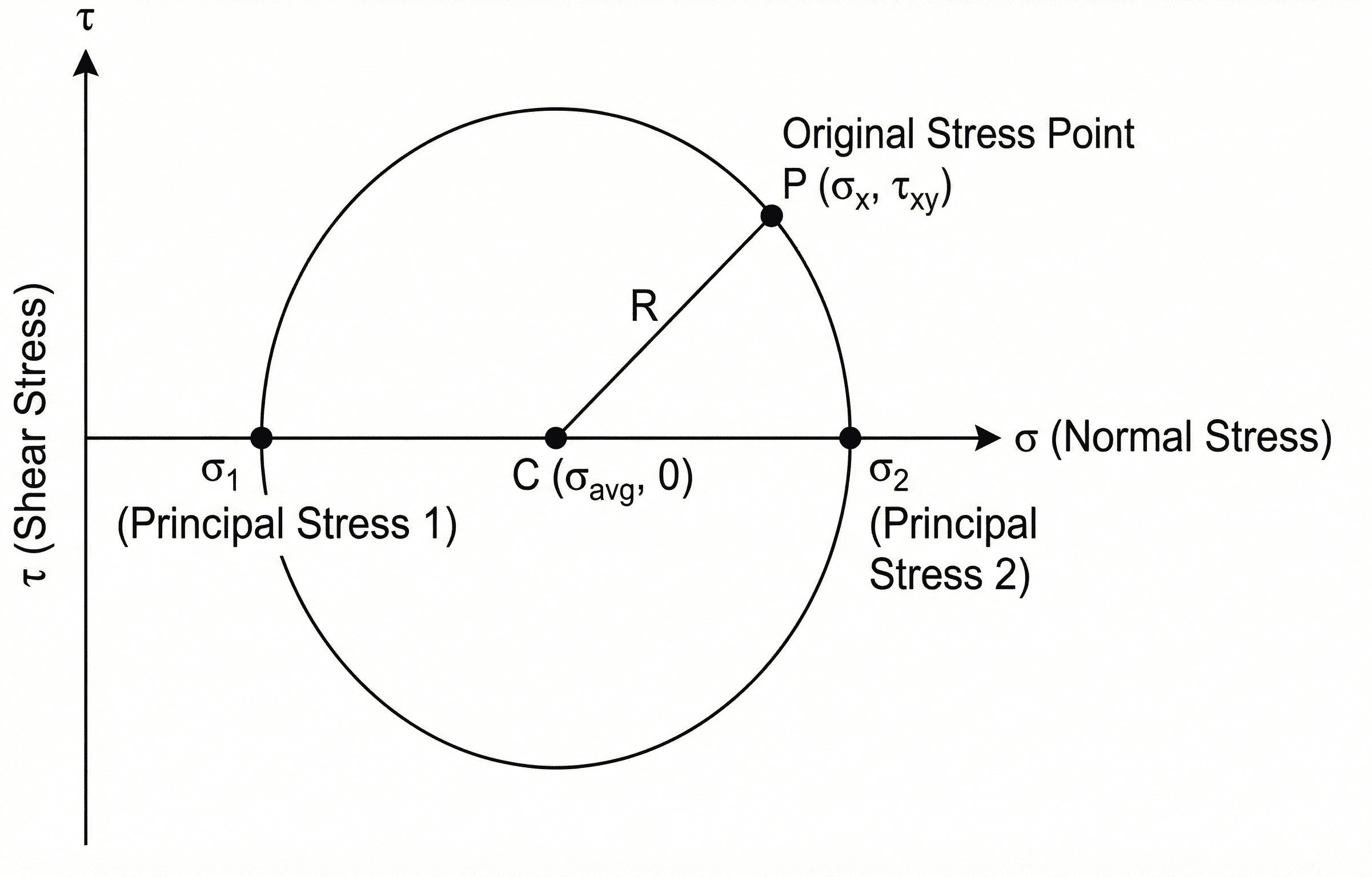
Notice the three pieces first: the center \(C(\sigma_{\text{avg}},0)\), the original stress point \(P(\sigma_x,\tau_{xy})\), and the two axis intercepts \(\sigma_1\) and \(\sigma_2\). Once those are understood, most Mohr’s Circle problems become a consistent workflow rather than a memorization exercise.
What is Mohr’s Circle?
Mohr’s Circle is a graphical method for representing a two-dimensional state of stress at a point. Instead of repeatedly substituting angles into the plane-stress transformation equations, you plot the known stress state on a \(\sigma\)-\(\tau\) coordinate system and use the geometry of a circle to read off stresses on rotated planes.
In practice, engineers use Mohr’s Circle when they are not just asking for a number, but for insight. It quickly answers questions such as: Which plane carries the principal stress? How large is the maximum in-plane shear stress? How far is the current stress state from pure tension, pure compression, or pure shear?
That is why it appears so often in mechanics of materials, machine design, pressure vessel interpretation, combined loading checks, and exam-style stress transformation problems. The real value is not only that it gives the correct answer, but that it shows how stress redistributes as the cut plane rotates.
The Mohr’s Circle formulas
For a plane stress state defined by \(\sigma_x\), \(\sigma_y\), and \(\tau_{xy}\), the center of the circle is the average normal stress and the radius is the distance from that center to the known stress point.
These expressions tell the full story. The center \(\sigma_{\text{avg}}\) shifts the circle horizontally, the radius \(R\) controls how large the stress swing becomes as orientation changes, the principal stresses are the horizontal intercepts, and the maximum in-plane shear stress equals the radius.
If the radius is small, the stress state changes only modestly as the plane rotates. If the radius is large, orientation matters a great deal and the difference between principal and nonprincipal planes becomes important.
Variables and units
Mohr’s Circle is unit-agnostic, but the arithmetic is not. Every stress component must use the same unit system before you compute the center, radius, or principal stresses.
- \(\sigma_x\) Normal stress on the face whose outward normal points in the \(x\)-direction; usually reported in Pa, kPa, MPa, psi, or ksi.
- \(\sigma_y\) Normal stress on the perpendicular face; it must use the same stress units as \(\sigma_x\).
- \(\tau_{xy}\) In-plane shear stress acting on the stress element; sign convention must stay consistent throughout the problem.
- \(\sigma_{\text{avg}}\) Average normal stress, which gives the center of the circle on the \(\sigma\)-axis.
- \(R\) Radius of the circle; equal to the maximum in-plane shear stress magnitude.
- \(\theta\) Physical rotation angle of the material plane. The corresponding movement on Mohr’s Circle is \(2\theta\).
Never mix MPa and psi or ksi and psi inside the same setup. Convert first, then build the circle.
The principal stresses should always be centered around \(\sigma_{\text{avg}}\). If \(\sigma_1\) and \(\sigma_2\) do not average back to \(\sigma_{\text{avg}}\), something is wrong in the setup.
| Variable | Meaning | SI units | US customary units | Typical interpretation | Notes |
|---|---|---|---|---|---|
| \(\sigma_x,\sigma_y\) | Normal stresses at a point | Pa, kPa, MPa | psi, ksi | Tension or compression | Tension is often taken as positive unless the sign convention states otherwise |
| \(\tau_{xy}\) | In-plane shear stress | Pa, kPa, MPa | psi, ksi | Stress tending to rotate or slide the element | One sign error here can flip angle results |
| \(\theta\) | Physical plane rotation | degrees or radians | degrees or radians | Actual cut-plane orientation | Mohr’s Circle uses \(2\theta\), not \(\theta\) |
How engineers use Mohr’s Circle step by step
Mohr’s Circle is less about algebraic rearrangement and more about executing a reliable sequence. In most engineering work, the fastest path is to compute the center, compute the radius, identify the principal stress intercepts, and then connect circle movement to the physical rotation of the plane.
- Start with the known plane-stress components \(\sigma_x\), \(\sigma_y\), and \(\tau_{xy}\).
- Compute the average normal stress \(\sigma_{\text{avg}} = (\sigma_x+\sigma_y)/2\).
- Compute the radius \(R\).
- Find the principal stresses with \(\sigma_1=\sigma_{\text{avg}}+R\) and \(\sigma_2=\sigma_{\text{avg}}-R\).
- Recognize that the maximum in-plane shear stress is \(R\), centered at \(\sigma_{\text{avg}}\).
- Use the angle relationship carefully to connect the geometry of the circle to the actual material orientation.
A physical rotation of \(\theta\) corresponds to a movement of \(2\theta\) on the circle. Many otherwise-correct solutions fail only because that angle relationship is mishandled.
In real design work, the question is rarely “Can I compute transformed stress?” It is usually “Which orientation actually governs failure, crack initiation, yielding, or margin?” Mohr’s Circle helps answer that quickly.
Worked example
Example problem
A point in a plate is subjected to \(\sigma_x = 80\text{ MPa}\), \(\sigma_y = 20\text{ MPa}\), and \(\tau_{xy} = 30\text{ MPa}\). Find the principal stresses and the maximum in-plane shear stress.
First compute the center:
Next compute the radius:
Now compute the principal stresses:
The maximum in-plane shear stress is simply the radius:
Physically, both principal stresses remain tensile because the average stress is high enough that subtracting the radius does not drive the smaller principal stress into compression.
A quick check is to verify that \((\sigma_1+\sigma_2)/2 = 50\text{ MPa}\), which matches the computed center. That confirms the arithmetic is internally consistent.
Assumptions behind Mohr’s Circle
Mohr’s Circle is powerful because it turns stress transformation into geometry, but that simplicity depends on assumptions that should stay visible while you work.
- 1 The problem is being treated as a two-dimensional plane-stress or plane-strain interpretation, not a fully three-dimensional stress state.
- 2 The stress components used are correct for the point of interest. Mohr’s Circle cannot fix bad input data.
- 3 The sign convention for normal and shear stress is applied consistently from start to finish.
- 4 The goal is stress transformation and interpretation, not direct prediction of yielding, fracture, buckling, or fatigue life.
Neglected factors
Mohr’s Circle by itself does not include material nonlinearity, plasticity, notch sensitivity, fracture mechanics, local stress concentrations, fatigue damage, or three-dimensional confinement effects. Those may matter more than the transformed stress state itself once design moves past a first-pass interpretation.
- Stress concentrations near holes, fillets, weld toes, and supports.
- Nonlinear material behavior once yielding or cracking begins.
- Out-of-plane stresses in thick members or multiaxial states.
- Time-dependent or cyclic effects such as creep and fatigue.
When Mohr’s Circle breaks down as a stand-alone tool
Mohr’s Circle becomes less reliable as a final decision tool when the problem is no longer well described by 2D stress transformation. That happens in thick components, multiaxial stress states, contact-dominated problems, nonlinear materials, and failure modes that depend on more than principal stress orientation alone.
Do not stop at Mohr’s Circle when the design is governed by 3D stress, local yielding, brittle fracture, fatigue life, buckling, or severe stress concentration effects.
Before trusting the circle, ask whether the point being evaluated is actually representative of the controlling location. If the point sits near a discontinuity or concentrated load, a nominal stress transformation may be too optimistic.
Common mistakes and engineering checks
- Using the wrong sign convention for \(\tau_{xy}\).
- Forgetting that the circle angle is \(2\theta\), not \(\theta\).
- Mixing stress units during the center and radius calculations.
- Reading principal stress correctly but using the wrong physical plane angle.
- Treating Mohr’s Circle as a failure criterion instead of a stress-transformation tool.
The principal stresses must always lie symmetrically around \(\sigma_{\text{avg}}\), and the maximum in-plane shear stress must equal the radius. If either condition fails, recheck the setup.
| Check item | What to verify | Why it matters |
|---|---|---|
| Units | All stress terms use the same unit system | Mixed units corrupt the center, radius, and intercepts |
| Average stress | \((\sigma_1+\sigma_2)/2 = \sigma_{\text{avg}}\) | This is the fastest arithmetic consistency check |
| Radius | \(\tau_{\max,\text{in-plane}} = R\) | Confirms the geometry and the shear interpretation match |
| Angle logic | The circle moves by \(2\theta\) | Prevents one of the most frequent orientation errors |
Frequently asked questions
Mohr’s Circle shows how normal stress and shear stress vary as the plane through a point rotates. It lets you identify principal stresses, maximum in-plane shear stress, and the corresponding plane orientations.
Because the plane-stress transformation equations are written in terms of \(\sin(2\theta)\) and \(\cos(2\theta)\). A physical plane rotation of \(\theta\) therefore maps to a geometric movement of \(2\theta\) on the circle.
The radius is the distance from the circle center to the plotted stress point. It equals the maximum in-plane shear stress and measures how strongly the stress state changes with orientation.
It should not be treated as the final answer when the problem is governed by three-dimensional stress, strong local stress concentrations, nonlinear material behavior, fracture, fatigue, or instability. In those cases, Mohr’s Circle is still useful for interpretation, but not sufficient by itself.
Summary and next steps
Mohr’s Circle is one of the clearest ways to move from a raw 2D stress state to an interpretable engineering answer. It shows where the principal stresses occur, how large the maximum in-plane shear stress becomes, and how stress changes as the plane rotates.
The most important judgment point is not the arithmetic. It is knowing whether the underlying stress state is actually representative and whether the design problem needs only transformation or a fuller failure, fatigue, fracture, or stability check.
Where to go next
Continue your learning path with these curated next steps.
-
Prerequisite: Shear Stress Equation
Strengthen your understanding of shear stress before moving deeper into transformed stress states.
-
Current topic: Mohr’s Circle
Return here when you need the main formulas, angle logic, worked example, and common engineering checks in one place.
-
Advanced: Hooke’s Law
Extend stress interpretation into linear-elastic material response and stress-strain relationships.