Key Takeaways
- Definition: Liquefaction is the earthquake-induced loss of effective stress and shear strength in saturated, loose, cohesionless soil.
- Use case: This page helps engineers judge when seismic shaking can trigger settlement, lateral spreading, or loss of bearing support.
- Main decision: The key engineering task is deciding whether the hazard is tolerable, needs more analysis, or requires mitigation.
- Outcome: You will understand the mechanism, screening workflow, design implications, and where simplified methods stop being enough.
Table of Contents
Introduction
In brief: Liquefaction happens when earthquake shaking raises pore-water pressure in loose saturated soil until the soil temporarily loses effective stress and much of its shear strength.
Who it’s for: Students, FE/PE prep, and seismic site designers.
For informational purposes only. See Terms and Conditions.
Liquefaction matters because a site can look acceptable under static loading but perform poorly during shaking, causing settlement, tilting, lateral movement, and major foundation distress.
Liquefaction infographic
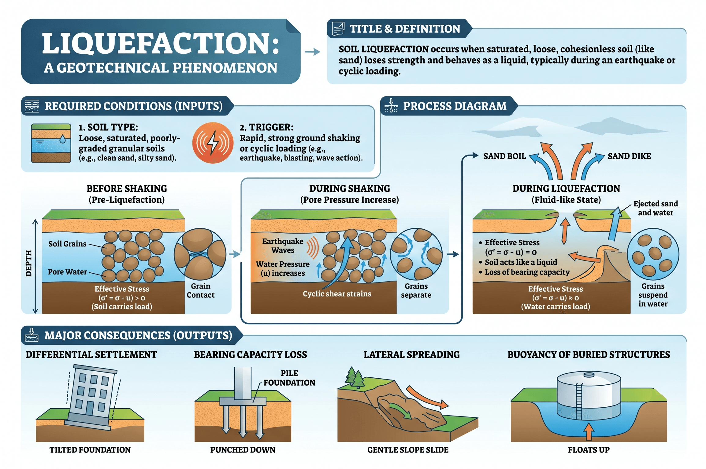
Notice the sequence rather than any single symptom. Engineers do not evaluate liquefaction by asking only “Can the soil liquefy?” They ask what layers are vulnerable, how strong the shaking is, how groundwater influences the response, and whether the likely consequence is vertical settlement, lateral spreading, downdrag, or loss of support beneath a structure.
What is liquefaction?
Liquefaction is a seismic soil behavior problem, not just a dramatic earthquake buzzword. It occurs mainly in loose to medium-dense, saturated, granular soils when cyclic shear stresses from earthquake shaking generate excess pore-water pressure faster than the soil can drain. As pore pressure rises, effective stress drops. Because soil strength and stiffness depend strongly on effective stress, the material can temporarily behave like a much weaker mass.
In practice, liquefaction is important because the damaging effect is rarely limited to the soil layer itself. Once a vulnerable stratum softens, structures above it may settle, pile foundations may lose lateral support, buried utilities can float, quay walls may move outward, and gently sloping ground may spread laterally toward a river, channel, or waterfront.
That is why liquefaction belongs in the same engineering conversation as soil mechanics, foundation design, ground improvement, and pile foundations. The triggering mechanism may be seismic, but the consequences are structural, serviceability-related, and often project-defining.
Core principles, variables, and units
The central idea is effective stress. In geotechnical engineering, total stress is shared between the soil skeleton and the pore water. When shaking drives pore-water pressure upward, the portion carried by grain-to-grain contact decreases. That reduction in effective stress is what lowers stiffness and shear resistance.
Key variables and typical ranges
Liquefaction screening usually combines site loading, subsurface resistance, groundwater position, and seismic demand. Engineers often work in SI or US customary units, but the logic stays the same: compare cyclic demand to cyclic resistance, then decide whether deformation risk is acceptable.
- \(a_{max}\) Peak horizontal ground acceleration; often expressed as a fraction of \(g\).
- \(\sigma_v\) Total vertical overburden stress at the depth of interest.
- \(\sigma’_v\) Effective vertical stress, which falls as pore pressure rises.
- CSR Cyclic stress ratio, a simplified measure of earthquake demand imposed on the soil.
- CRR Cyclic resistance ratio, typically inferred from SPT, CPT, or shear-wave velocity correlations.
- FS Factor of safety against triggering, commonly expressed as \(CRR / CSR\).
- \(r_d\) Stress reduction coefficient accounting for depth-dependent soil column flexibility.
A liquefaction check is never just a number at one depth. Always look for the continuity, thickness, and elevation of vulnerable layers relative to the groundwater table and foundation bearing level.
Decision logic and evaluation workflow
A good liquefaction workflow starts with consequences, not equations. First identify whether the project is sensitive to settlement, lateral spreading, downdrag, or temporary bearing loss. Then decide whether a screening-level check is adequate or whether the site needs deformation-focused analysis and mitigation planning.
Establish seismic hazard → define groundwater and vulnerable soil layers → obtain field data (SPT, CPT, or \(V_s\)) → screen for triggering → estimate consequences such as settlement or spreading → compare with project tolerance → mitigate, redesign, or document acceptable risk.
What controls the decision?
Three things usually control: the density and fabric of the soil, the severity of shaking, and what happens if the layer softens. A parking lot and a hospital may share the same subsurface profile, but the design decision can be very different because the acceptable consequence is different.
Where engineers often lose time
Teams often over-focus on the triggering factor of safety and under-focus on deformation. A site with marginal triggering may still perform acceptably if the vulnerable layer is thin and laterally discontinuous. Another site with a similar factor of safety may be unacceptable if it supports an abutment, tank, waterfront structure, or critical pipeline.
Equations and calculations
For introductory liquefaction screening, the demand side is often summarized with the cyclic stress ratio. One widely taught simplified form is:
Here, \(a_{max}\) represents the peak horizontal ground acceleration at the ground surface, \(g\) is gravitational acceleration, \(\sigma_v\) is total vertical stress, \(\sigma’_v\) is effective vertical stress, and \(r_d\) reduces the stress estimate with depth. The resistance side is commonly estimated from corrected SPT blow counts, corrected CPT tip resistance, or shear-wave velocity correlations. A screening factor of safety is then written as:
This format is useful because it separates the problem into demand and resistance, but it is still a simplification. Magnitude scaling, fines content corrections, overburden effects, aging, cementation, and stress history all matter. In other words, the equation is a framework for engineering judgment, not a replacement for it.
Worked example
Example
Suppose a site investigation identifies a loose saturated sand layer at about 15 ft below grade. The groundwater table is shallow, and the project is a low-rise structure near a riverbank where lateral movement would be more damaging than simple vertical settlement. Assume a screening-level seismic demand with \(a_{max}/g = 0.30\), \(\sigma_v / \sigma’_v = 1.8\), and \(r_d = 0.90\).
The cyclic stress ratio is:
If corrected field data indicate a cyclic resistance ratio of about 0.24 for the layer, then:
A factor of safety below 1.0 suggests triggering is plausible under the selected shaking scenario. But that is not the end of the design question. The next step is to ask what the consequence is. Because the site is near a free face, lateral spreading may govern. That could push the team toward additional exploration, deformation estimates, and mitigation such as densification, ground improvement, or a foundation system less sensitive to lateral soil strength loss.
Engineering judgment and field reality
Field reality rarely matches a perfectly layered textbook soil profile. Liquefaction potential can change dramatically across a site because loose lenses, reclaimed fills, old channel deposits, and variable fines content create pockets of vulnerability. One boring may show a concerning interval while another, only a short distance away, looks benign.
Groundwater is another field reality issue. Engineers often inherit groundwater levels measured during one season, one drilling event, or one construction phase. If the design is sensitive to liquefaction, ask whether the reported groundwater table is representative of high groundwater conditions, long-term equilibrium, and post-irrigation or waterfront behavior.
Also remember that field performance is not governed by triggering alone. A site may trigger but experience tolerable settlements. Another may trigger and suffer severe spreading because the geometry, slope, and free-face conditions amplify displacement. That difference is why experienced engineers tie the hazard back to the specific structure and not just the subsurface report.
Sand boils are memorable, but many costly liquefaction problems show up as settlement, downdrag, embankment deformation, or lateral displacement with little dramatic surface evidence at the building footprint itself.
Where this method breaks down
Simplified liquefaction triggering methods are powerful, but they break down when they are treated as universal. Correlations are best suited to the soil types and case histories they were developed from. Unusual gradations, cemented sands, gravelly soils, aging effects, very shallow crusts, or complex cyclic loading histories can fall outside the comfort zone of a basic screening chart.
Screening methods also do not directly answer all deformation questions. A site with a modest triggering factor of safety may still require a separate evaluation of post-liquefaction settlement, lateral spreading displacement, pile kinematics, or embankment stability. For high-consequence structures, a simple factor of safety alone is not enough design information.
Fine-grained soils create another common boundary. Some silts and low-plasticity materials may behave in a liquefaction-like manner, while more plastic soils are often better described using cyclic softening or cyclic degradation concepts. Using a sand-based framework without checking soil behavior type can lead to misleading conclusions.
Common pitfalls and engineering checks
- Assuming liquefaction is only a concern for “clean sand” and ignoring susceptible silty granular deposits.
- Using one groundwater depth without asking whether seasonal highs or perched water conditions matter.
- Checking triggering but not settlement, spreading, downdrag, or temporary loss of lateral support.
- Relying on sparse borings when the vulnerable layer may be lens-shaped or laterally variable.
- Mixing corrected and uncorrected field parameters in the same evaluation workflow.
One of the most expensive mistakes is concluding “the site is safe” because the average condition looks acceptable, even though a localized loose saturated layer controls the actual failure mechanism.
| Check item | Why it matters | Typical data source | Engineering note |
|---|---|---|---|
| Groundwater depth | Liquefaction requires saturation or near-saturation | Borings, wells, seasonal records | Use a representative high groundwater condition where appropriate |
| Soil behavior type | Controls whether sand-based correlations are appropriate | Logs, gradation, Atterberg limits, CPT | Do not force fine-grained cyclic softening into a clean-sand framework |
| Layer continuity | Thin discontinuous lenses behave differently from thick continuous strata | Borings, CPT transects, geologic model | Continuity often matters more than a single point value |
| Consequence mechanism | Settlement and lateral spreading drive different design responses | Site geometry and structural system | Always connect hazard to the actual performance requirement |
Visualizing liquefaction consequences
The most useful mental picture is to separate triggering from consequence. Triggering happens inside the soil. Consequences happen in the ground surface, foundation system, and surrounding infrastructure. One site may show mostly settlement and reconsolidation. Another may experience lateral spreading toward a free face. Another may cause pile bending because the surrounding soil suddenly provides far less lateral confinement.
If you later add a second visual, the most valuable option would be a text-and-sketch comparison of settlement, lateral spreading, and pile response rather than a duplicate mechanism diagram.
Relevant standards and design references
Liquefaction evaluation sits at the intersection of field testing, seismic hazard definition, and project-specific performance criteria. These references usually matter most:
- ASTM D1586: Governs Standard Penetration Test procedures used in many liquefaction screening workflows.
- ASTM D5778/D5778M: Covers electronic friction cone and piezocone penetration testing, commonly used for CPT-based liquefaction correlations.
- ASTM D7400/D7400M: Addresses downhole seismic testing that may support shear-wave velocity based screening.
- ASCE 7 seismic provisions: Provide the broader structural seismic framework and hazard context used in design.
- FEMA and agency geotechnical guidance: Useful for consequence-focused evaluation, mitigation selection, and performance-based interpretation.
Frequently asked questions
Liquefaction usually refers to saturated granular soils losing effective stress and shear strength during cyclic shaking, while cyclic softening more often describes repeated-load strength degradation in finer or more plastic soils that do not fully behave like liquefied sand.
Yes. Sand boils are a useful field clue, but liquefaction can occur at depth without dramatic ejecta at the surface, showing up instead as settlement, spreading, loss of support, or excess pore pressure response.
Engineers commonly reduce risk by densifying the soil, improving drainage, using stone columns or grouting, modifying the structural system, or selecting deep foundations that bypass vulnerable layers where that approach fits the project.
No. A screening factor of safety is only one input to design; the final judgment also depends on deformation tolerance, uncertainty in the data, layer continuity, structural sensitivity, and whether spreading or settlement is the real controlling issue.
Summary and next steps
Liquefaction is best understood as a loss of effective stress problem driven by cyclic loading in saturated, vulnerable soil. The engineering task is not just identifying whether triggering can occur, but understanding what that means for settlement, lateral spreading, foundation performance, and project risk.
In practice, the most reliable workflow is to combine sound subsurface characterization, appropriate screening or advanced analysis, and a consequence-based design mindset. That is where engineering judgment matters most: knowing when a basic screening result is enough and when the project requires mitigation, a different foundation concept, or deeper performance evaluation.
Where to go next
Continue your learning path with these curated next steps.
-
Read a deeper dive on Soil Mechanics
Build the effective stress, drainage, and shear strength foundation that underpins liquefaction behavior.
-
Study seismic testing and dynamic site characterization
Useful when you need better field data for shear-wave velocity and dynamic soil response.
-
Explore ground improvement options
A natural next step when liquefaction risk is real but the project needs a practical mitigation path.