Key Takeaways
- Core idea: Stormwater drainage design routes rainfall runoff from developed surfaces into a controlled system of grading, inlets, pipes, storage, treatment, and protected discharge points.
- Engineering use: Engineers use drainage design to reduce roadway flooding, protect buildings, control peak runoff, prevent erosion, and meet local stormwater criteria.
- What controls it: Drainage area, rainfall intensity, runoff coefficient, time of concentration, inlet spacing, pipe slope, hydraulic grade line, detention storage, and tailwater conditions drive the design.
- Practical check: A drainage system can be correctly sized on paper and still fail if inlet bypass, clogging, emergency overflow, maintenance access, or outfall erosion is ignored.
Table of Contents
Introduction
Stormwater drainage design is the engineering process of collecting, conveying, controlling, and discharging rainfall runoff so developed sites do not flood, erode, or overload downstream systems. A complete design connects surface grading, gutters, inlets, storm sewer pipes, detention or retention storage, water quality controls, emergency overflow routes, and protected outfalls into one coordinated drainage system.
How Stormwater Moves Through a Drainage System
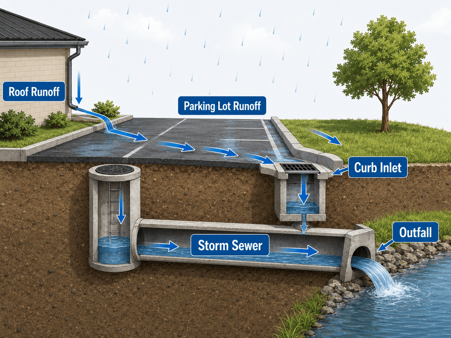
Notice that the system is not only an underground pipe. The surface grading, curb flow, inlet location, access structures, pipe slope, receiving channel, and overflow route all affect whether the drainage system performs during a storm.
What is Stormwater Drainage Design?
Stormwater drainage design is the planning and sizing of infrastructure that manages runoff from rainfall. On a developed site, rainfall lands on rooftops, pavement, lawns, landscaped areas, streets, and other surfaces. Some water infiltrates, some is temporarily stored, and the rest becomes runoff that must be safely routed.
In water resources engineering, drainage design connects hydrology and hydraulics. Hydrology estimates how much runoff a storm creates and how quickly it arrives. Hydraulics determines whether gutters, inlets, pipes, channels, detention facilities, and outfalls can convey or control that runoff without creating unacceptable flooding, erosion, surcharge, or maintenance problems.
Stormwater drainage design focuses on moving runoff safely through a site or roadway system. Stormwater management is broader and may include detention, retention, infiltration, pollutant reduction, permitting, and downstream impact control. Flood management is broader still and may include floodplain storage, riverine flooding, emergency planning, and regional infrastructure.
A stormwater plan is only as good as its weakest link. A site may have a properly sized pipe network, but if runoff bypasses the inlets, the hydraulic grade line rises above a rim, or the outfall erodes the receiving channel, the drainage design can still fail in the field.
Hydrology vs. Hydraulics in Drainage Design
Stormwater drainage design usually begins with hydrology and then moves into hydraulics. Confusing the two can lead to designs that estimate runoff correctly but fail to convey it, or designs that size pipes without understanding the storm flow entering the system.
| Design question | Hydrology | Hydraulics |
|---|---|---|
| How much runoff is generated? | Estimates peak flow or hydrograph volume from rainfall, land cover, drainage area, and time of concentration. | Uses the resulting flow as an input, but does not usually create the runoff estimate. |
| How fast does water arrive? | Evaluates flow path, slope, roughness, and time of concentration. | May evaluate timing in complex systems or storage routing. |
| Can the inlet capture runoff? | Provides the approach flow to the inlet. | Checks gutter spread, inlet type, inlet capacity, sag conditions, and bypass flow. |
| Can the pipe carry the design flow? | Provides the design discharge. | Checks diameter, slope, roughness, velocity, head loss, surcharge, and hydraulic grade line. |
| Will the outfall damage the channel? | Helps estimate discharge rate and event frequency. | Checks outlet velocity, tailwater, energy dissipation, riprap, and receiving channel stability. |
A drainage report should make it clear which calculations estimate runoff and which calculations check conveyance. If those steps are blurred together, inlet bypass, pipe surcharge, and tailwater effects are easier to miss.
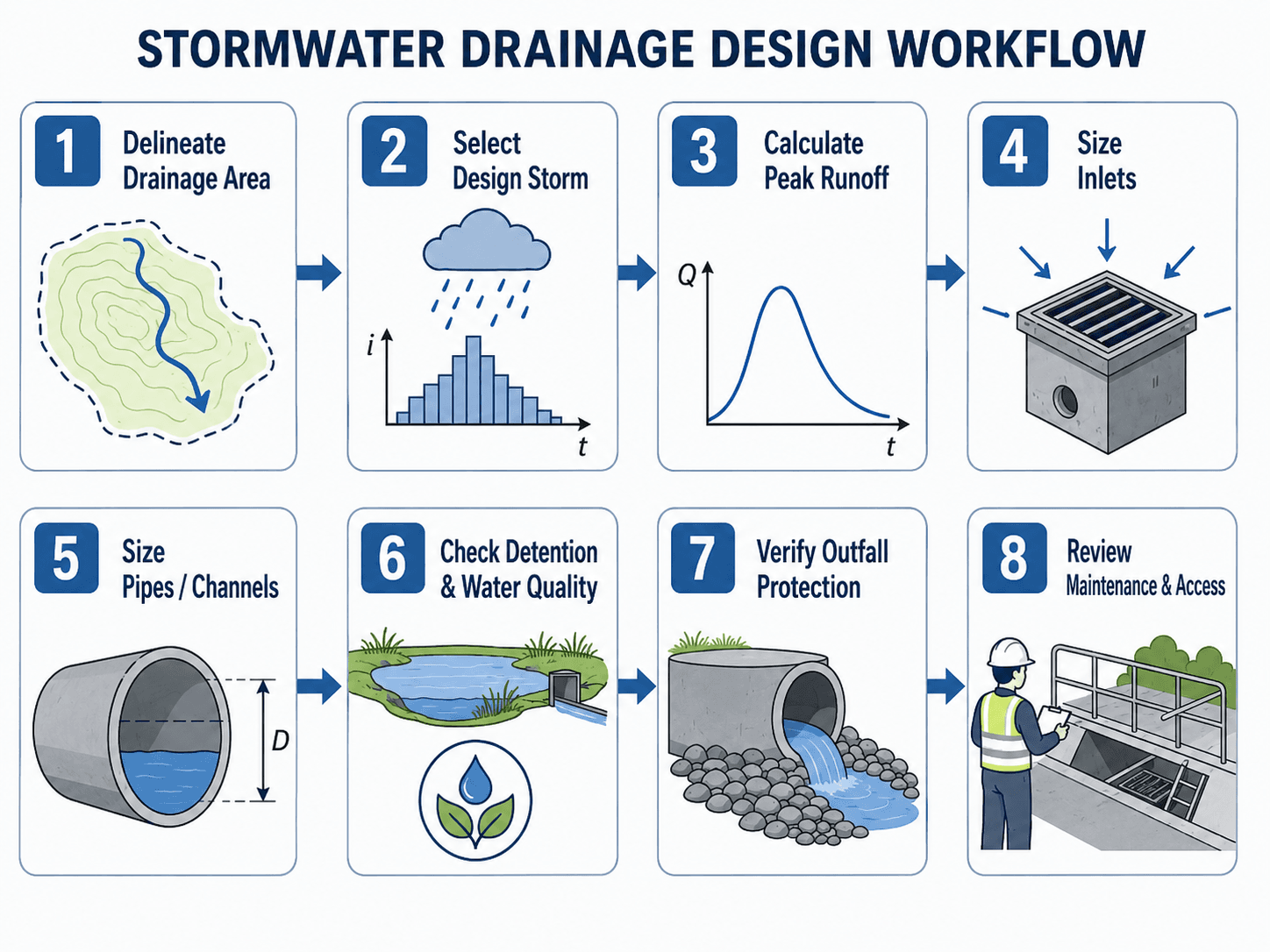
Stormwater Drainage Design Workflow
A good stormwater drainage design follows a sequence. Engineers first define where runoff comes from, then estimate flow rates, then size the collection and conveyance system, and finally check storage, water quality, outfall protection, emergency overflow, and maintenance access.
1. Define the drainage areas
The drainage area is the surface that contributes runoff to a specific inlet, ditch, pipe, pond, or outfall. Designers usually divide a site into smaller subcatchments based on grading, roof leaders, curb lines, pavement slopes, swales, and low points.
2. Select the design storm and estimate runoff
The design storm sets the rainfall intensity or rainfall depth used for analysis. Local criteria may require different storm events for the minor drainage system, detention storage, emergency overflow, and flood protection. For small drainage areas, engineers often estimate peak runoff with the Rational Method.
3. Size the collection and conveyance system
Inlets must capture runoff without excessive gutter spread or bypass. Pipes and channels must convey the design flow with acceptable velocity, cover, slope, head loss, and hydraulic grade line. The design also needs practical access points for inspection and maintenance.
Stormwater Drainage Design Criteria Engineers Must Confirm
Stormwater drainage criteria are usually set by the city, county, state DOT, drainage district, owner, or authority reviewing the project. Before sizing inlets and pipes, engineers need to know which storm events, spread limits, detention requirements, and outfall assumptions apply.
| Criteria item | What to confirm | Why it affects the design |
|---|---|---|
| Minor storm event | The design storm used for inlets, gutters, storm sewer laterals, and typical pipe capacity checks. | Controls the everyday drainage system that keeps roads, lots, and site areas usable during common storms. |
| Major storm event | The larger storm used to check overland flow, emergency overflow, pond freeboard, and safe conveyance routes. | Shows where water goes when the pipe system is exceeded or partially blocked. |
| Allowable gutter spread | The maximum width of water allowed to spread into travel lanes, parking aisles, sidewalks, or site access routes. | Can control inlet spacing even when the pipe network has adequate capacity. |
| Minimum pipe size and slope | Local minimums for storm sewer diameter, cover, slope, material, and cleanout or manhole spacing. | Prevents pipes that are too small to inspect, too flat to self-clean, or too shallow to protect. |
| Velocity limits | Minimum velocity for sediment transport and maximum velocity for erosion or structural protection. | Very flat pipes can collect sediment; high outlet velocities can damage downstream channels. |
| Hydraulic grade line criteria | Required clearance below inlet rims, manhole rims, finished floor elevations, or ground surface. | Prevents surcharge from backing water onto pavement or into building-adjacent areas. |
| Detention release rate | Allowable post-development discharge, pre-development comparison method, outlet control rules, and drawdown time. | Controls basin size, outlet structure geometry, and downstream impact mitigation. |
| Water quality volume or treatment criteria | Required treatment volume, pollutant removal approach, pretreatment, or stormwater control measure sizing. | Affects basin layout, forebays, filters, infiltration areas, and long-term maintenance requirements. |
| Outfall and tailwater assumptions | Receiving water elevation, channel capacity, erosion protection, and downstream connection constraints. | Can raise the hydraulic grade line or require riprap, energy dissipation, or outlet relocation. |
Main Components of a Stormwater Drainage System
Stormwater drainage design works because several components act together. Surface grading moves runoff toward collection points. Inlets capture the flow. Pipes and channels convey it. Storage facilities control peak discharge or volume. Outfalls release water to a receiving system without damaging the downstream channel.
| Component | Design role | Common review concern |
|---|---|---|
| Site grading | Directs runoff away from buildings, roads, and critical low points. | Low spots, reverse slopes, and flow paths that send water toward structures. |
| Curb and gutter | Collects shallow surface flow along streets and parking areas. | Excessive spread, bypass flow, ponding at sag points, and unsafe water near travel lanes. |
| Curb inlets and catch basins | Capture runoff and transfer it into the underground drainage system. | Inlet spacing, clogging, sag capacity, grate safety, curb opening length, and bypass during heavy storms. |
| Manholes and junctions | Provide access and connect laterals, trunk lines, and changes in pipe direction or slope. | Structure losses, rim elevations, access spacing, pipe conflicts, and maintenance safety. |
| Storm sewer pipes | Convey runoff by gravity toward a pond, channel, storm sewer trunk line, or outfall. | Pipe diameter, slope, velocity, cover, head losses, and hydraulic grade line. |
| Detention or retention facility | Stores runoff to reduce peak discharge, manage volume, or support water quality treatment. | Outlet control, storage volume, emergency spillway, drawdown time, forebay design, and sediment maintenance. |
| Protected outfall | Discharges stormwater into a channel, ditch, pond, or downstream drainage system. | Riprap, erosion control, tailwater, bank stability, energy dissipation, and downstream capacity. |
Stormwater Drainage Design Inputs and Outputs
A drainage design becomes easier to review when each design stage clearly identifies its inputs and outputs. This prevents the common mistake of jumping directly to pipe sizing without confirming the runoff assumptions or the downstream control point.
| Design stage | Typical inputs | Typical outputs |
|---|---|---|
| Hydrology | Drainage area, land cover, runoff coefficient, rainfall intensity, time of concentration, design storm. | Peak flow, runoff volume, or hydrograph used for downstream sizing and routing. |
| Inlet and gutter design | Approach flow, gutter slope, cross slope, inlet type, allowable spread, sag or on-grade location. | Inlet spacing, inlet size, capture capacity, bypass flow, and spread depth. |
| Storm sewer design | Design flow, pipe slope, roughness, pipe material, cover, junction layout, downstream tailwater. | Pipe diameter, velocity, hydraulic grade line, energy losses, and surcharge check. |
| Detention or retention design | Inflows, allowable release rate, basin geometry, outlet control, drawdown criteria, emergency overflow. | Storage volume, outlet structure, stage-storage-discharge relationship, and freeboard check. |
| Water quality design | Contributing impervious area, treatment volume, pollutants of concern, pretreatment needs, soil or infiltration conditions. | Stormwater control measure size, forebay layout, filter area, or treatment train configuration. |
| Outfall design | Discharge, velocity, pipe diameter, tailwater, channel condition, soil stability, downstream property constraints. | Riprap sizing approach, energy dissipation, headwall protection, and stable discharge location. |
What Controls Stormwater Drainage Design?
The controlling factor is not always obvious. In one project, inlet spread may control. In another, downstream tailwater may control. In a redevelopment project, an existing pipe or outfall easement may be the limiting condition.
| Control | Why it matters | Engineering implication |
|---|---|---|
| Impervious area | Roofs, pavement, and compacted surfaces produce runoff quickly. | More impervious area usually increases peak flow, inlet demand, pipe size, and detention volume. |
| Time of concentration | Shorter travel times often produce higher rainfall intensity for small storm drainage areas. | Unreasonable time of concentration values can overstate or understate peak runoff. |
| Inlet spacing | Controls how much surface flow reaches each inlet before bypass occurs. | May require additional inlets even if downstream pipes have adequate capacity. |
| Pipe slope | Controls gravity flow capacity and velocity. | Flat slopes can surcharge or collect sediment; steep slopes can create erosive outlet velocities. |
| Hydraulic grade line | Shows how high water rises in the storm sewer system under design flow. | Controls rim surcharge risk, low-point flooding, and clearance near buildings or pavement. |
| Tailwater | Represents downstream water level at the outfall or connection point. | Can reduce outlet capacity and force water to back up through the pipe network. |
| Emergency overflow path | Provides a safe route when the pipe system is exceeded. | Protects buildings and critical infrastructure during storms larger than the minor system design event. |
Minor System vs. Major System in Stormwater Drainage Design
Many stormwater designs separate the drainage system into a minor system and a major system. The minor system handles more frequent design storms through inlets, gutters, pipes, and storm sewers. The major system handles larger or overflow events through surface flow paths, streets, swales, emergency spillways, and designated pond overflow routes.
| System | Typical elements | Primary design question |
|---|---|---|
| Minor drainage system | Curbs, gutters, catch basins, curb inlets, manholes, storm sewer pipes, laterals, and trunk lines. | Can the normal collection and conveyance system handle the selected design storm without unacceptable spread, surcharge, or flooding? |
| Major drainage system | Overland flow routes, road crowns, swales, detention basin emergency spillways, open channels, and safe overflow paths. | Where does water go when the minor system is exceeded, blocked, or affected by tailwater? |
“No flooding in the pipe design storm” is not the same as “safe during an extreme storm.” A strong drainage plan shows what happens when rainfall exceeds the minor system or when an inlet is blocked.
Inlet Design, Gutter Spread, Pipe Sizing, and Hydraulic Grade Line
Inlets and pipes are often designed together, but they answer different questions. Inlets answer whether surface runoff can enter the drainage system. Pipes answer whether captured runoff can move downstream without excessive head loss, velocity, or surcharge.
Inlet design and bypass flow
Inlets may be located on grade, where water continues flowing along the gutter, or in a sag, where water ponds at a low point. On-grade inlets often allow some bypass flow. Sag inlets may capture more flow but are sensitive to clogging because water has fewer alternate routes.
Gutter spread is the width of water on the pavement or gutter section. Allowable spread can control inlet spacing on roads, parking lots, drive aisles, and pedestrian areas. A design that ignores spread may meet pipe capacity requirements but still create unsafe or unacceptable surface ponding.
Pipe sizing and velocity
Storm sewer pipes are commonly checked for capacity, velocity, slope, roughness, cover, and constructability. Minimum velocity is often considered to reduce sediment deposition, while maximum velocity and outlet velocity are checked to avoid erosion or structural issues.
Hydraulic grade line and tailwater
The hydraulic grade line shows the water surface or pressure level through the storm sewer system. When tailwater is high, pipes are flat, or junction losses are significant, the hydraulic grade line can rise above pipe crowns and may approach inlet or manhole rims. That condition can create surcharge, surface flooding, or backwater into upstream structures.
Do not stop at normal-depth pipe capacity. For critical networks, check inlet spread, bypass flow, junction losses, hydraulic grade line, tailwater, and where water will surface if the system exceeds capacity.
Common Stormwater Drainage Design Equations
Drainage design often combines simple hand calculations with local criteria and hydraulic modeling. Two common equations are the Rational Method for estimating peak runoff and Manning’s equation for checking pipe, gutter, swale, or channel capacity.
Rational Method for peak runoff
The Rational Method is commonly used for small drainage areas where peak flow is the main design concern. In US customary stormwater practice, the common form is:
- \(Q\) Peak runoff rate, commonly expressed in cubic feet per second for US customary design.
- \(C\) Runoff coefficient representing land cover, imperviousness, slope, soil response, and surface storage.
- \(i\) Rainfall intensity for the selected storm and time of concentration.
- \(A\) Drainage area contributing to the design point.
Manning’s equation for conveyance capacity
Manning’s equation is widely used to estimate open-channel and gravity pipe flow. It helps check whether the proposed pipe, ditch, swale, or channel can carry the design flow at the selected slope and roughness.
- \(Q\) Flow rate through the pipe, gutter, swale, or channel.
- \(n\) Manning roughness coefficient based on material and flow resistance.
- \(A\) Flow area of the water section.
- \(R\) Hydraulic radius, equal to flow area divided by wetted perimeter.
- \(S\) Energy slope or pipe slope for many uniform-flow design checks.
These equations are useful screening and design tools, but they do not replace local stormwater criteria, hydraulic grade line checks, inlet spread calculations, detention routing, or site-specific modeling when those are required.
Worked Stormwater Drainage Design Example
A short example shows how a peak runoff calculation becomes a starting point for inlet, pipe, detention, and outfall design. This example is intentionally simplified so the design logic is clear.
Example peak runoff calculation
Assume a small paved drainage area drains to a curb inlet. The contributing drainage area is 2.5 acres, the runoff coefficient is 0.85, and the rainfall intensity for the selected design storm and time of concentration is 4.2 inches per hour.
What the result means
The estimated peak flow of 8.9 cfs is not the final drainage design. It is the design flow that must be checked against inlet capture, gutter spread, pipe capacity, hydraulic grade line, detention routing, and outfall protection. If the inlet can only capture part of the flow before bypass occurs, the system needs additional or larger inlets even if the downstream pipe can carry 8.9 cfs.
Stormwater drainage design should be checked at each control point. The controlling element may be the inlet, the gutter spread, the pipe, the detention outlet, the tailwater condition, or the downstream channel—not necessarily the largest visible pipe.
Stormwater Drainage Design Tradeoffs
Drainage design is not always a matter of making every component larger. Engineers balance capacity, cost, constructability, maintenance, water quality, available space, safety, and downstream impacts.
| Design decision | Potential benefit | Tradeoff to review |
|---|---|---|
| Add more inlets | Reduces gutter spread, bypass flow, and surface ponding. | Increases cost, maintenance points, utility conflicts, and structure count. |
| Use larger storm sewer pipes | Reduces surcharge risk and may lower hydraulic grade line. | May increase excavation depth, conflict with utilities, and raise project cost. |
| Increase detention storage | Reduces peak discharge and downstream impact. | Requires land area, stable embankments, outlet control, emergency overflow, and maintenance access. |
| Flatten detention outlet release | Better controls downstream peak flow. | May increase drawdown time, clogging sensitivity, or standing water concerns. |
| Use surface overflow routes | Provides resilience when the storm sewer is exceeded or blocked. | Requires careful grading so overflow does not reach buildings, critical equipment, or unsafe pedestrian areas. |
| Add riprap or energy dissipation at outfall | Reduces erosion and outlet scour. | Needs correct sizing, filter layer consideration, access, and long-term channel stability review. |
Detention, Retention, and Water Quality Context
Modern drainage design often goes beyond moving water away quickly. Many projects also need to reduce peak discharge, manage runoff volume, treat pollutants, or protect downstream channels from erosion and sediment loading.
| Stormwater control | Main purpose | Drainage design connection |
|---|---|---|
| Detention | Temporarily stores runoff and releases it more slowly. | Reduces peak discharge but requires outlet control, emergency spillway, and drawdown review. |
| Retention | Stores water permanently or relies on infiltration, evaporation, or reuse. | Can reduce runoff volume but depends on soil, groundwater, maintenance, and storage assumptions. |
| Infiltration practices | Encourage stormwater to enter the soil. | Can reduce runoff but may be limited by soil permeability, groundwater, contamination risk, or setbacks. |
| Water quality treatment | Reduces sediment, nutrients, trash, hydrocarbons, or other pollutants. | Often requires pretreatment, treatment volume, forebays, filters, vegetation, or maintenance plans. |
| Outfall stabilization | Protects the receiving channel from concentrated discharge. | Connects pipe hydraulics to downstream erosion control and channel stability. |
Parking lots, streets, rooftops, and industrial areas can carry sediment, oil, grease, trash, nutrients, metals, and other pollutants into storm drains. That is why stormwater drainage design often overlaps with treatment trains, green infrastructure, and stormwater control measures.
Senior Engineer Stormwater Drainage Design Checklist
A practical stormwater drainage design review should confirm that runoff reaches the system, the system has enough capacity, and the downstream discharge is controlled. The checklist below is designed to catch issues that basic pipe sizing often misses.
Start upstream with grading and drainage areas, move through inlets and pipes, then finish downstream with detention, water quality, outfall protection, emergency overflow, and maintenance access. Do not approve the design just because one pipe sizing table looks acceptable.
| Review check | What to look for | Why it matters |
|---|---|---|
| Drainage areas match grading | Subcatchment boundaries follow actual slopes, curb lines, roof leaders, and low points. | Wrong drainage areas lead to wrong peak flows before any pipe sizing begins. |
| Design storm matches criteria | Minor system, major system, detention, and emergency overflow storms are checked separately when required. | Local agencies often use different storm events for different performance objectives. |
| Inlet capacity and bypass are checked | Spread, grate capacity, curb opening capacity, sag inlet behavior, clogging allowance, and downstream bypass are reviewed. | An undersized or poorly located inlet can flood a site even when the storm sewer pipe is large enough. |
| Pipe capacity and hydraulic grade line are reasonable | Pipe diameter, slope, roughness, junction losses, cover, and surcharge risk are checked. | A system that flows under pressure may back up into inlets, manholes, pavement, or building-adjacent areas. |
| Minor and major systems both work | The pipe system and surface overflow route are checked for their appropriate design events. | Protects the site when storms exceed the minor system or when inlets are blocked. |
| Detention and water quality are integrated | Storage volume, outlet control, forebay, treatment volume, and maintenance points are coordinated. | Prevents a conveyance-only design from missing regulatory or downstream impact requirements. |
| Outfall protection is included | Riprap, energy dissipation, outlet velocity, tailwater, and channel stability are reviewed. | Concentrated discharge can erode banks, undermine pipes, and send sediment downstream. |
| Maintenance access is realistic | Manholes, cleanouts, access roads, pond forebays, and inspection routes are shown. | Systems that cannot be maintained eventually lose capacity from debris, sediment, vegetation, or structural damage. |
Engineering Judgment and Field Reality
Real stormwater systems rarely behave exactly like clean diagrams. Leaves block grates, sediment reduces capacity, pavement settles, construction changes flow paths, vegetation grows into swales, and downstream water levels can rise during the same storm that loads the drainage system.
Experienced designers look for how water will behave when the system is partially blocked, when a storm exceeds the design event, or when maintenance is delayed. This is why overflow routes, emergency spillways, accessible inlets, and stable outfalls are part of good stormwater drainage design.
The surface overflow path matters. When inlets clog or pipes surcharge, stormwater follows the grading, not the design report. A good plan shows where excess water will go without damaging buildings or creating unsafe ponding.
When Hand Calculations Are Not Enough
Simplified stormwater drainage design methods become less reliable when the site, storm event, or downstream system is complex. In those cases, designers may need hydrologic modeling, hydraulic modeling, detention routing, hydraulic grade line analysis, or agency-specific procedures.
- Large or complex watersheds where runoff timing from multiple subareas affects the peak flow.
- Flat storm sewer systems where small changes in tailwater, pipe slope, or junction losses can cause surcharge.
- Sites with detention routing, pump stations, backwater, submerged outfalls, or downstream capacity restrictions.
- Urban redevelopment projects where existing pipes, legacy inlets, and undocumented drainage connections affect performance.
- Projects where the reviewing agency requires a hydrologic or hydraulic model as part of the drainage submittal.
- Extreme storm checks where emergency overflow paths control safety more than the minor storm sewer system.
When modeling is required, water resources modeling helps connect rainfall, runoff, storage, pipe hydraulics, and downstream boundary conditions into one reviewable system.
Common Stormwater Drainage Design Failure Points
Many drainage failures are not caused by a single bad calculation. They happen when debris, grading, inlet spacing, pipe capacity, outfall stability, tailwater, and maintenance realities are not considered together.
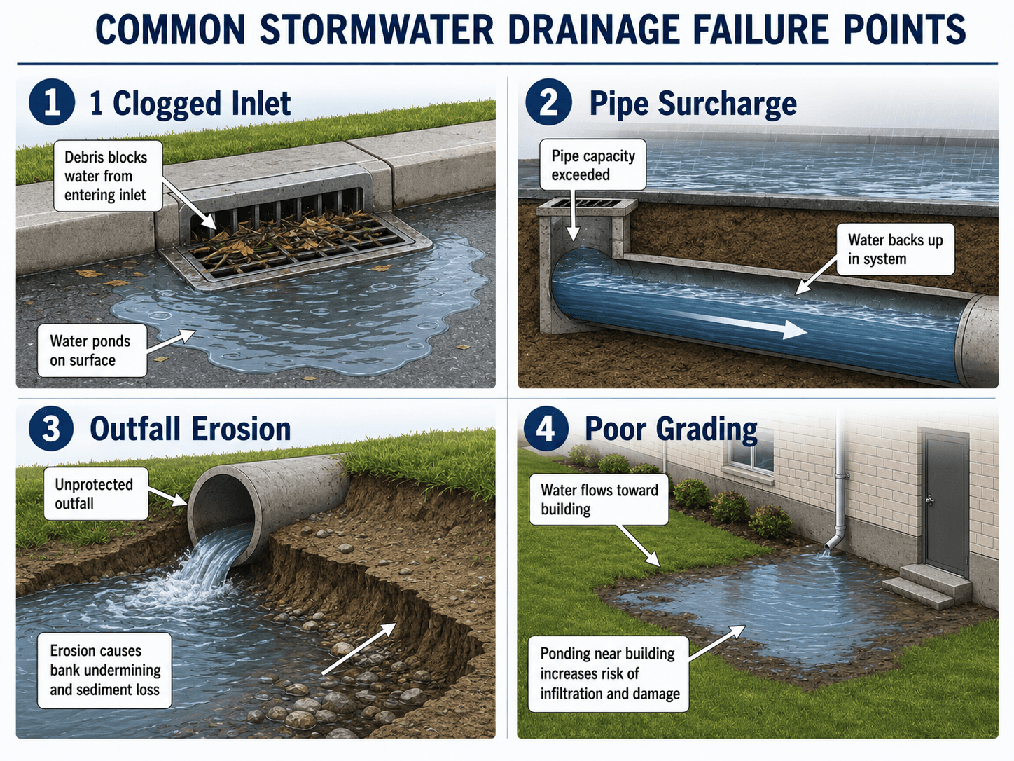
- Ignoring inlet clogging: Leaves, sediment, trash, and construction debris can reduce capture capacity.
- Checking pipe capacity but not inlet spread: Water may bypass the inlet before it ever reaches the pipe.
- Forgetting tailwater: A downstream water surface can back up the system and raise the hydraulic grade line.
- Forgetting the outfall: High outlet velocity can erode channels and undermine the end of the pipe.
- Relying on ideal grading: Field grading, settlement, and pavement tolerance can shift runoff toward unintended low points.
- Missing maintenance access: A stormwater system that cannot be cleaned or inspected will lose capacity over time.
The most common design trap is treating stormwater drainage as a pipe-sizing problem only. The system must also capture water at the surface, route overflow safely, control discharge, protect the outfall, and remain maintainable after construction.
Relevant Manuals, Data Sources, and Design References
Stormwater drainage design is controlled by local criteria, but national manuals are useful for understanding accepted hydrologic and hydraulic design methods. Designers typically combine local rainfall data, agency requirements, site survey, grading plans, drainage area maps, and hydraulic calculations.
- FHWA Urban Drainage Design Manual: FHWA HEC-22 Urban Drainage Design Manual provides practical guidance for storm drainage systems, including rainfall and runoff, pavement drainage, gutter flow, inlet design, storm drain piping, detention facilities, pump stations, and urban water quality practices.
- Project-specific criteria: City, county, state DOT, drainage district, owner, or development criteria may control design storms, allowable spread, detention release rates, water quality volume, and submittal requirements.
- Engineering use: References are used to select design methods, check assumptions, support calculations, and confirm that drainage systems are reviewed as complete surface-and-pipe networks rather than isolated components.
Frequently Asked Questions
Stormwater drainage design is the engineering process of collecting, conveying, controlling, and discharging rainfall runoff from developed sites so roads, buildings, landscapes, and downstream channels are protected from flooding, erosion, and water quality impacts.
The main steps are to delineate drainage areas, select the design storm, estimate peak runoff, size inlets, size pipes or channels, check detention and water quality requirements, verify outfall protection, and confirm maintenance access.
The Rational Method is commonly used to estimate peak runoff for small drainage areas, while Manning’s equation is commonly used to check gravity flow capacity in pipes, gutters, swales, and open channels.
Stormwater drainage focuses on collecting and conveying runoff safely, while stormwater management is broader and may include detention, retention, infiltration, pollutant reduction, permitting, erosion control, and downstream impact control.
Stormwater drainage systems often fail because of clogged inlets, underestimated runoff, undersized pipes, poor grading, excessive bypass flow, inadequate outfall protection, sediment buildup, tailwater effects, or failure to account for local design criteria and maintenance access.
Summary and Next Steps
Stormwater drainage design is the practical engineering process of turning rainfall into a controlled drainage path. It links surface grading, runoff estimation, inlet capture, storm sewer capacity, detention or retention storage, water quality controls, emergency overflow, and outfall protection.
The strongest designs are not just mathematically sized; they are reviewable, maintainable, and resilient when field conditions are imperfect. In practice, engineers check drainage areas, design storms, inlet bypass, pipe capacity, hydraulic grade line, overflow routes, detention controls, and downstream erosion risk together.
Where to go next
Continue your learning path with related Turn2Engineering resources.
-
Hydrology
Build the rainfall-runoff foundation needed to understand drainage area response, peak flow, and watershed behavior.
-
Stormwater Management
Learn how drainage design connects to runoff control, detention, retention, BMPs, and water quality strategies.
-
Water Resources Modeling
Explore how hydrologic and hydraulic models are used when simple drainage calculations are not enough.