Key Takeaways
- Core idea: An open system allows mass and energy to cross the system boundary.
- Engineering use: Mechanical engineers model open systems as control volumes for turbines, compressors, pumps, nozzles, heat exchangers, and valves.
- What controls it: Mass flow rate, enthalpy, velocity, elevation, heat transfer, work transfer, and boundary assumptions control the analysis.
- Practical check: Always verify whether the device is actually steady flow before simplifying the mass and energy balances.
Table of Contents
Introduction
An open system in thermodynamics is a system where both mass and energy can cross the boundary. In mechanical engineering, open systems are usually analyzed as control volumes so engineers can track flow rate, heat transfer, work transfer, and fluid energy through devices such as turbines, compressors, pumps, nozzles, and heat exchangers.
Open Systems Compared With Closed and Isolated Systems
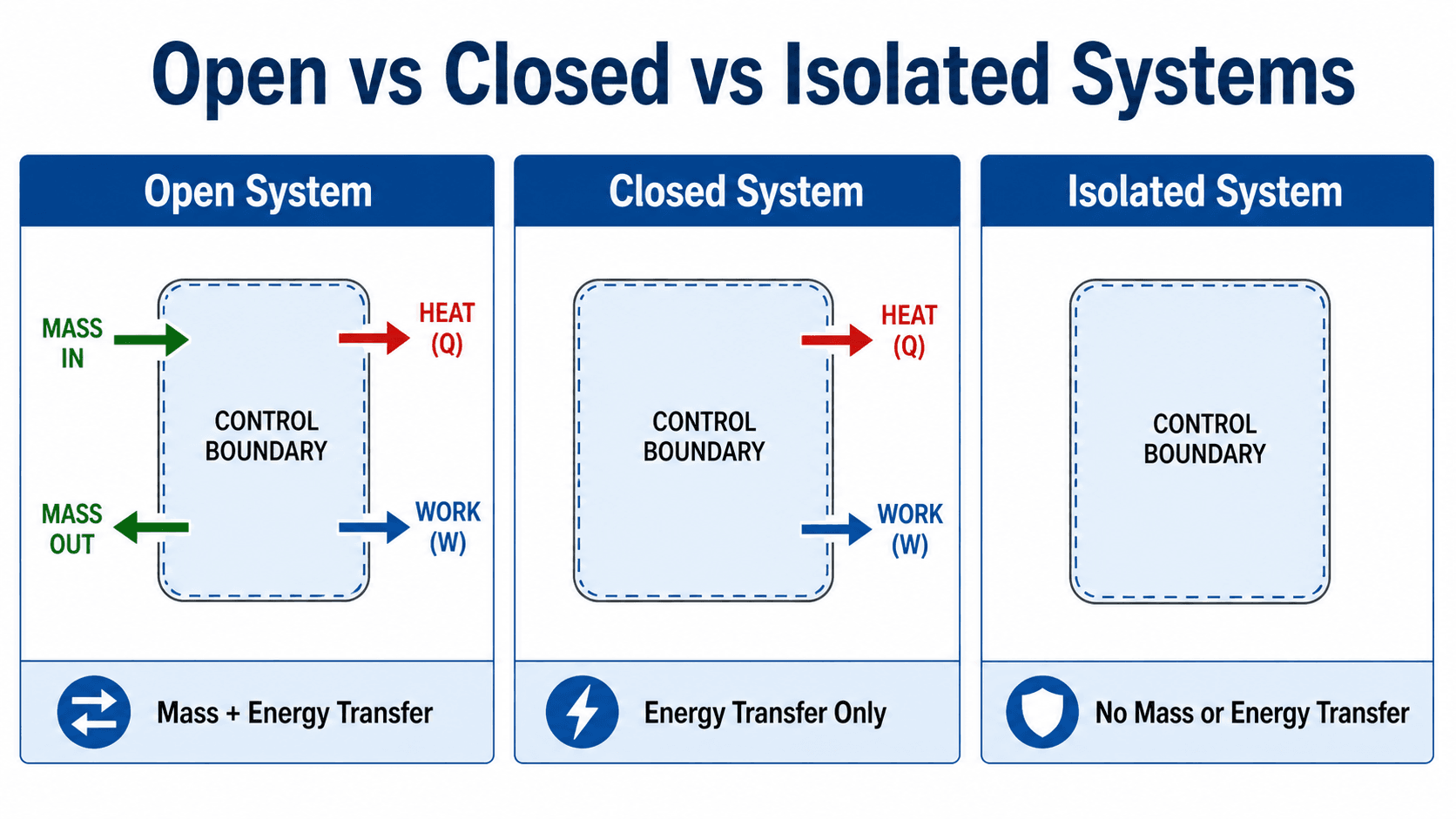
Notice that the defining feature of an open system is not whether the equipment is physically open to the air. The defining feature is whether mass crosses the chosen system boundary.
What Is an Open System?
An open system is a thermodynamic model where matter can enter or leave while energy can also cross the boundary as heat, work, or energy carried by the flowing mass. In engineering analysis, the boundary is usually called a control-volume boundary, and the region inside it is the control volume.
This distinction matters because most real mechanical equipment does not operate as a fixed lump of material. Steam flows through a turbine, refrigerant flows through a compressor, water flows through a pump, and air flows through a nozzle. The equipment may be bolted shut, but thermodynamically it is still an open system because mass crosses the analysis boundary.
A closed system follows a fixed amount of mass. An open system watches a region in space and tracks what flows in, what flows out, and how energy crosses the boundary.
Open vs Closed vs Isolated Systems
The easiest way to classify a thermodynamic system is to ask what crosses the boundary. An open system allows mass and energy transfer. A closed system allows energy transfer but keeps the same mass inside the boundary. An isolated system is an idealized system where neither mass nor energy crosses the boundary.
| System type | Mass crosses boundary? | Energy crosses boundary? | Typical thermodynamics example |
|---|---|---|---|
| Open system | Yes | Yes | Turbine, compressor, pump, nozzle, heat exchanger, throttling valve. |
| Closed system | No | Yes | Sealed piston-cylinder with a fixed amount of gas. |
| Isolated system | No | No, ideally | An idealized perfectly insulated and sealed system. |
This comparison is important because the wrong system model leads to the wrong equation. A pump cannot be analyzed as a closed system if liquid is continuously flowing through it, and a sealed piston-cylinder should not be analyzed as an open system if no mass enters or leaves.
How Control Volumes Make Open Systems Usable
A control volume lets engineers draw an analysis boundary around a device and apply conservation laws to that region. The boundary may follow the physical casing of a pump, a section of duct, the shell of a heat exchanger, or an imaginary surface around a mixing chamber.
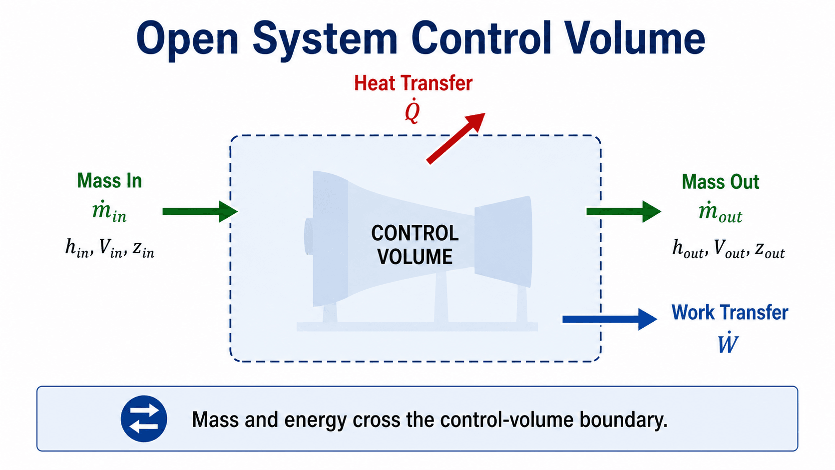
Mass crosses at inlets and outlets
The mass flow rate is usually written as \( \dot{m} \). For a single-inlet, single-outlet device at steady flow, the inlet and outlet mass flow rates are equal. For multi-stream devices such as mixing chambers and heat exchangers, the sum of inlet mass flow rates must match the sum of outlet mass flow rates if no mass is accumulating inside the control volume.
Energy crosses in more than one form
Energy may cross the boundary as heat transfer \( \dot{Q} \), shaft work \( \dot{W} \), or energy carried by the flowing fluid. That flow energy is commonly written using enthalpy because enthalpy includes internal energy plus the flow work needed to push fluid across the boundary.
Mass Balance and Energy Balance for Open Systems
The two core tools for analyzing open systems are conservation of mass and conservation of energy. These equations are not just academic formulas; they are the bookkeeping system behind turbine power, compressor work input, pump sizing, nozzle velocity, heat-exchanger duty, and throttling-valve behavior.
General mass balance
This equation says that the rate of mass accumulation inside the control volume equals total mass flow in minus total mass flow out. If the device is operating at steady flow, the mass inside the control volume is not changing with time.
General control-volume energy balance
The terms inside the parentheses represent energy carried by flowing mass: enthalpy, kinetic energy, and potential energy. For many turbines, compressors, pumps, and heat exchangers, kinetic and potential energy changes are small compared with enthalpy changes. For nozzles and diffusers, velocity change is often the main point, so kinetic energy should not be ignored.
Steady-flow energy equation
- \( \dot{m} \) Mass flow rate, commonly in kg/s or lbm/s.
- \( h \) Specific enthalpy, commonly in kJ/kg or Btu/lbm.
- \( V \) Average flow velocity at an inlet or outlet, commonly in m/s or ft/s.
- \( z \) Elevation relative to a chosen datum, commonly in m or ft.
- \( \dot{Q}, \dot{W} \) Heat-transfer rate and work-transfer rate, commonly in kW or Btu/hr.
Common Open-System Devices in Thermodynamics
Most open-system problems become easier once the device type is recognized. Each device has a typical purpose, a typical energy interaction, and a typical set of assumptions. The equations are the same conservation laws, but the terms that matter change from device to device.
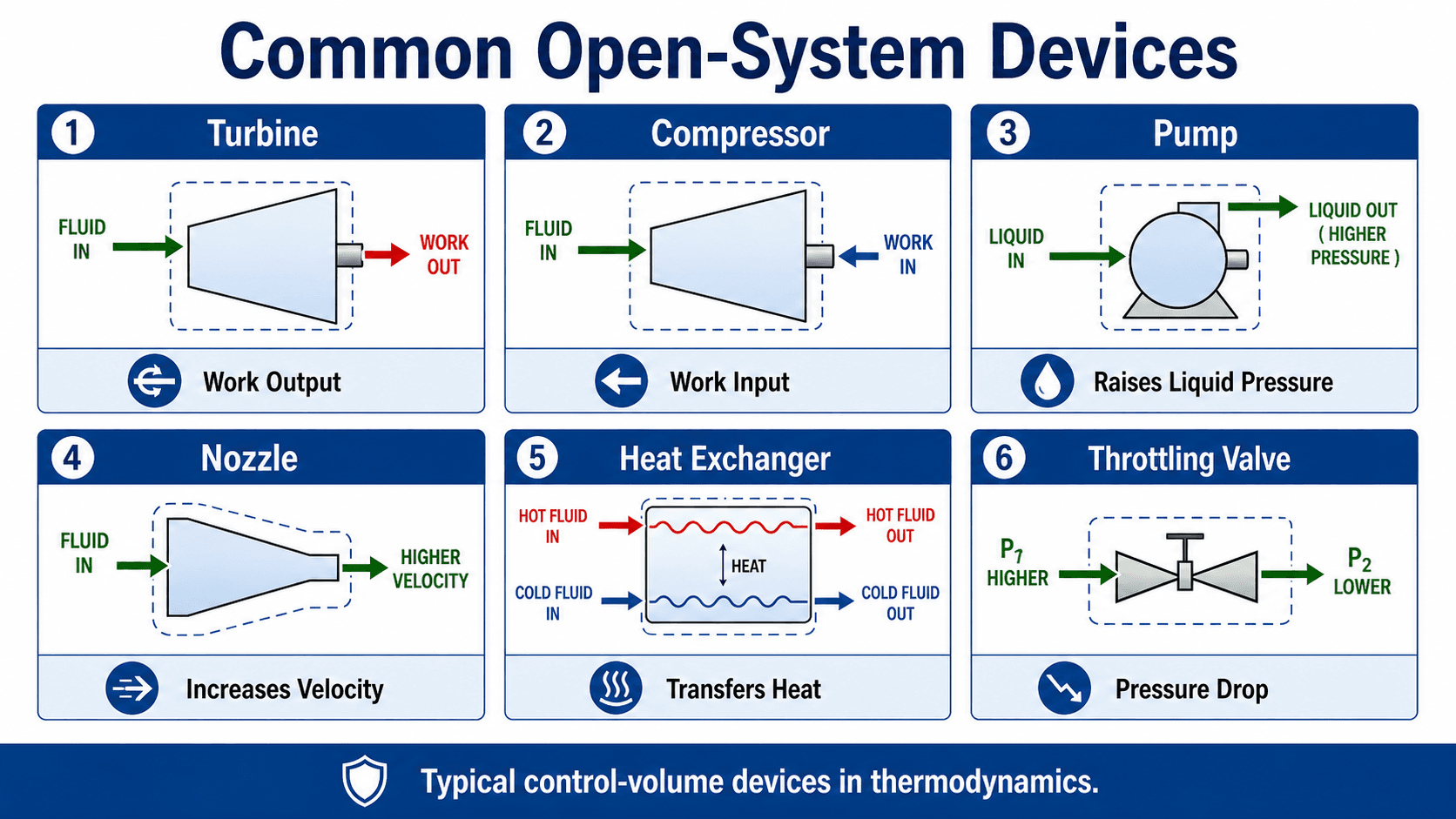
| Device | Main engineering purpose | Typical simplification |
|---|---|---|
| Turbine | Extract shaft work from a flowing fluid. | Often modeled as steady and approximately adiabatic, with work output driven by enthalpy drop. |
| Compressor | Increase gas pressure using work input. | Usually modeled with work input and an enthalpy rise; heat loss may matter in real equipment. |
| Pump | Increase liquid pressure using work input. | Often treated as nearly incompressible, with relatively small temperature change. |
| Nozzle | Increase fluid velocity. | Kinetic energy change is usually important; shaft work is normally zero. |
| Heat exchanger | Transfer heat between fluid streams. | Usually no shaft work; energy is exchanged between streams rather than created. |
| Throttling valve | Drop pressure through a restriction. | Often modeled as \( h_1 \approx h_2 \) when heat, work, and kinetic energy changes are negligible. |
When to Use the Steady-Flow Model
The steady-flow model is the most common open-system simplification, but it should not be used automatically. It works when the device has reached normal operation and the properties at each inlet and outlet are not changing with time.
Start by drawing the control volume. Mark every inlet and outlet. List heat and work interactions. Check whether mass is accumulating. Then decide which terms are small enough to neglect: kinetic energy, potential energy, heat transfer, shaft work, or storage inside the control volume.
| Check or decision | What to look for | Why it matters |
|---|---|---|
| Is the control volume steady? | Inlet and outlet properties do not change with time. | If properties are changing, the storage term cannot be ignored. |
| Are all inlets and outlets included? | Every pipe, bleed stream, leak path, condensate drain, or bypass flow is accounted for. | Missing a stream breaks both mass balance and energy balance. |
| Is kinetic energy important? | Large velocity changes, especially in nozzles, diffusers, jets, and high-speed ducts. | Ignoring velocity terms can badly underestimate or overestimate outlet conditions. |
| Is shaft work present? | Rotating shafts, pumps, compressors, fans, turbines, or motors connected to the device. | Work direction controls whether the device produces power or consumes power. |
| Is heat transfer negligible? | Insulation, short residence time, small surface area, or small temperature difference. | Assuming adiabatic behavior when heat loss is significant can distort performance estimates. |
Worked Example: Turbine as an Open System
Consider a steam turbine operating at steady flow. Steam enters with high enthalpy and leaves with lower enthalpy. If heat loss, kinetic energy change, and elevation change are small, the main energy conversion is from fluid enthalpy to shaft work.
Assumptions
- One inlet and one outlet.
- Steady-flow operation.
- Negligible heat transfer to the surroundings.
- Negligible kinetic and potential energy changes.
Simplified turbine relationship
If \( \dot{m} = 4 \, \text{kg/s} \), \( h_1 = 3200 \, \text{kJ/kg} \), and \( h_2 = 2500 \, \text{kJ/kg} \), then the estimated turbine power output is:
Engineering meaning
The result means the turbine is converting the enthalpy drop of the flowing steam into shaft power at about 2.8 MW under the stated assumptions. If the turbine has significant heat loss, moisture effects, mechanical losses, or large velocity changes, the simplified estimate should be refined.
Engineering Judgment and Field Reality
Real open systems rarely match textbook assumptions perfectly. Turbines lose energy through irreversibility and heat loss, compressors heat the gas more than ideal models predict, pumps may cavitate, heat exchangers foul over time, and valves can create noise, vibration, and large pressure losses.
The important engineering skill is not memorizing one simplified equation. It is deciding which terms are small, which terms control the result, and which assumptions are unsafe for the equipment being analyzed.
A steady-flow calculation can look mathematically correct while still being physically wrong if the control volume misses a bypass stream, assumes impossible heat transfer, ignores two-phase flow, or treats a startup condition as steady operation.
When This Breaks Down
Open-system analysis is still based on conservation laws, but the simple steady-flow form breaks down when the storage terms, transient behavior, or real-fluid effects become important.
- Startup and shutdown: Mass and energy stored inside the device may change rapidly with time.
- Filling and emptying tanks: The control volume has changing mass, pressure, temperature, or composition.
- Two-phase flow: Boilers, condensers, evaporators, and throttling valves may require careful phase-property evaluation.
- High-speed flow: Nozzles, diffusers, and compressible gas systems may require kinetic energy and Mach number effects.
- Leaks and bypasses: Unaccounted mass flow can make a clean-looking energy balance misleading.
Common Mistakes and Practical Checks
Most errors in open-system problems come from drawing the wrong boundary, using the wrong sign convention, or simplifying the energy equation before understanding the device.
- Calling a sealed device a closed system: A compressor casing may be sealed, but it is an open system if gas flows through it.
- Confusing open systems with isolated systems: An isolated system is an idealization with no mass or energy crossing the boundary, which is the opposite of how most flow devices operate.
- Forgetting flow work: Open-system energy equations usually use enthalpy because the flowing fluid carries internal energy and flow work.
- Neglecting kinetic energy everywhere: This may be acceptable for many pumps and heat exchangers but not for nozzles and diffusers.
- Mixing sign conventions: Be consistent about whether work output is positive or work input is positive.
Do not decide whether a system is open by looking for an open lid or exposed surface. Decide by asking whether mass crosses the chosen thermodynamic boundary.
Useful References and Design Context
Open systems are a foundational thermodynamics concept rather than a single code-controlled design method. Engineers usually apply textbook control-volume equations along with equipment data, operating conditions, property tables, and project-specific performance requirements.
- NPTEL thermodynamics reference: NPTEL first law of thermodynamics for open systems notes discuss the control-volume approach, steady-flow processes, unsteady-flow processes, and common devices such as turbines, compressors, and heat exchangers.
- Project-specific criteria: Equipment performance may depend on manufacturer curves, operating pressure, inlet state, outlet state, allowable temperature limits, safety margins, and owner performance requirements.
- Engineering use: Control-volume analysis is used to estimate power, heat duty, outlet state, energy losses, and whether the assumed device model is physically reasonable.
Frequently Asked Questions
An open system is a thermodynamic system where mass and energy can cross the system boundary. In mechanical engineering, open systems are usually analyzed as control volumes, such as turbines, compressors, pumps, nozzles, heat exchangers, boilers, condensers, and throttling valves.
An open system allows mass and energy transfer across the boundary, while a closed system allows energy transfer but does not allow mass transfer. A turbine is typically modeled as an open system because fluid flows through it, while a sealed piston-cylinder with fixed mass is commonly modeled as a closed system.
No. An isolated system ideally allows no mass or energy transfer across its boundary, while an open system allows both mass and energy transfer. Open systems are common in real engineering equipment, while perfectly isolated systems are idealizations.
The steady-flow energy equation can be used when mass flow rates and fluid properties at the inlets and outlets remain constant with time. It is commonly applied to devices operating at normal steady conditions, such as turbines, compressors, pumps, nozzles, diffusers, and heat exchangers.
Summary and Next Steps
Open systems are thermodynamic systems where mass and energy cross the system boundary. They are different from closed systems, where mass stays fixed, and isolated systems, where neither mass nor energy is ideally exchanged.
The key is to define the boundary clearly, identify every inlet and outlet, track heat and work transfer, and decide whether steady-flow assumptions are valid. Turbines, compressors, pumps, nozzles, heat exchangers, and throttling valves all use the same conservation principles, but each device emphasizes different terms in the energy equation.
Where to go next
Continue your learning path with related Turn2Engineering resources.
-
Closed Systems
Compare open systems with fixed-mass thermodynamic systems where no mass crosses the boundary.
-
Isolated Systems
Understand the idealized system type where neither mass nor energy crosses the boundary.
-
First Law of Thermodynamics
Review the energy-conservation principle behind heat, work, internal energy, and control-volume analysis.