Key Takeaways
- Core idea: Structural safety systems are not one device or material; they are the complete set of load-resisting elements, details, checks, and maintenance practices that keep a structure stable and usable.
- Engineering use: Engineers use safety systems to trace loads, prevent collapse, control movement, limit damage, and keep local problems from becoming system-wide failures.
- What controls it: The controlling issues are usually load path continuity, realistic loading, connection behavior, foundation support, redundancy, ductility, durability, and inspection quality.
- Practical check: A structure can look strong on paper and still be unsafe if field conditions, deterioration, modifications, or missing connections interrupt the intended system.
Table of Contents
Introduction
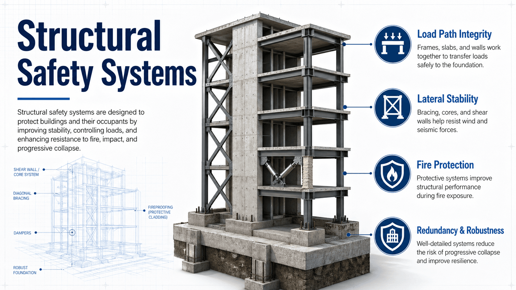
Structural safety systems are the coordinated structural elements, details, design methods, inspections, and monitoring practices that allow buildings and bridges to resist loads without collapse, instability, or unsafe performance. They include gravity framing, lateral force-resisting systems, foundations, connections, redundancy, ductility, fire and corrosion protection, and maintenance programs that keep the structure reliable over time.
How Structural Safety Systems Work Together
Notice that no single element protects the whole structure by itself. The important idea is continuity: gravity and lateral loads must have a complete path, and the structure needs enough redundancy, ductility, durability, and inspection to remain safe when conditions change.
What are Structural Safety Systems?
A structural safety system is the full arrangement of members, connections, foundations, details, design checks, and field controls that prevent unacceptable movement, instability, or collapse. In a building, this includes ordinary framing such as beams, slabs, columns, and walls, but it also includes less obvious safety features such as diaphragms, collectors, anchors, bracing, fire protection, corrosion protection, inspection programs, and structural health monitoring.
The key point is that structural safety is a system behavior. A beam can be strong, a column can be large, and a foundation can be massive, but the structure can still be unsafe if the load path is incomplete, the connection cannot transfer force, the lateral system is discontinuous, or deterioration has reduced the real capacity below the design assumption.
Structural safety is not just “strong materials.” It is the ability of the complete structure to collect loads, transfer them through reliable paths, tolerate local damage, and keep performing throughout its service life.
The Main Layers of Structural Safety
Structural safety systems work in layers. The first layer defines the loads. The second layer provides members that can resist those loads. The third layer connects everything into a continuous path. The fourth layer adds resilience through redundancy, ductility, and robustness. The final layer keeps the system reliable through inspection, maintenance, repair, and monitoring.
Gravity load system
The gravity system carries vertical loads such as self-weight, occupancy, furniture, stored materials, vehicles, snow, and roof loads. Slabs, joists, beams, girders, columns, bearing walls, trusses, and foundations must work together so vertical demand moves safely into the ground without excessive deflection, punching shear, buckling, settlement, or local overload.
Lateral force-resisting system
The lateral system resists wind, seismic forces, soil pressure, flood effects, and other horizontal or overturning actions. Common systems include shear walls, braced frames, moment frames, diaphragms, collectors, chords, hold-downs, base plates, and foundation anchors. A lateral system is only effective when floors and roofs can collect lateral loads and deliver them to the vertical resisting elements.
Connection and foundation system
Connections and foundations often control real safety because they are where idealized analysis becomes physical force transfer. Bolts, welds, rebar development, anchors, embed plates, bearing seats, shear keys, dowels, and footings must match the forces the structural model assumes. If the connection or support condition is wrong, the member strength may not matter.
How Engineers Use Safety Systems in Design and Review
Engineers use structural safety systems as a design framework, not just as a checklist of components. During design, the engineer defines likely hazards, chooses an appropriate structural system, checks strength and serviceability, details connections, coordinates foundations, and verifies that the final drawings can be built and inspected. During evaluation, the same logic is reversed: the engineer traces the existing load path, compares demand with capacity, and checks whether observed conditions match the original assumptions.
- New building design: Select gravity and lateral systems that match span, height, occupancy, seismicity, wind exposure, foundation conditions, material availability, and constructability.
- Existing building evaluation: Review drawings, inspect distress, verify use changes, assess deterioration, and determine whether repairs or strengthening are needed.
- Post-event assessment: Check structures after earthquakes, high winds, impacts, fires, floods, explosions, or unusual overloads.
- Design review: Confirm that load combinations, support assumptions, connection details, diaphragm paths, and foundation reactions are internally consistent.
Before accepting a safety system, ask: where does the load enter, what path does it follow, what element or connection controls, what happens if one part is damaged, and how will the system be inspected over time?
What Controls Structural Safety?
Structural safety depends on both calculated capacity and real-world reliability. A structure may pass a member check but still be vulnerable if the governing load was missed, the support condition was modeled incorrectly, the connection cannot be constructed as drawn, or long-term deterioration has reduced capacity.
| Factor | Why it matters | Engineering implication |
|---|---|---|
| Load path continuity | Forces must travel from the point of application to the foundation without interruption. | Missing collectors, weak anchors, discontinuous shear walls, or unsupported transfer members can control safety. |
| Demand versus capacity | Safety depends on comparing realistic loads with available resistance. | Underestimated loads, changed occupancy, added rooftop equipment, or heavier storage can invalidate earlier checks. |
| Connection behavior | Connections determine whether members act as assumed in the model. | Bolts, welds, anchors, bearing seats, and reinforcement development often control force transfer and failure mode. |
| Redundancy and robustness | Structures need alternate paths when one member, support, or connection is damaged. | Redundant framing and ties reduce the chance that local failure becomes disproportionate collapse. |
| Ductility | Ductile systems can deform and dissipate energy before sudden failure. | Seismic and extreme-event performance often depends on controlled yielding instead of brittle fracture or crushing. |
| Durability and exposure | Corrosion, moisture, fire, fatigue, freeze-thaw, chemicals, and rot reduce real capacity over time. | Protective details, inspections, drainage, coatings, cover, and repairs are part of the safety system. |
Demand, Capacity, and Safety Margins
Structural safety is often evaluated by comparing the demand placed on a member, connection, foundation, or system against its available resistance. The exact code format depends on the material, design method, and governing standard, but the practical idea is consistent: required strength must not exceed design strength, and serviceability must remain acceptable.
In this simplified strength-check format, \(D_u\) represents factored demand from applicable load combinations, \(R_n\) represents nominal resistance, and \(\phi\) represents a resistance factor that accounts for uncertainty in strength. This equation does not prove that a structure is safe by itself; it must be paired with stability, serviceability, ductility, detailing, durability, and load path checks.
- \(D_u\) Factored demand from gravity, wind, seismic, snow, soil, fluid, construction, or accidental loading.
- \(R_n\) Nominal resistance of the member, connection, foundation, or system before resistance reduction.
- \(\phi\) Resistance factor used in many strength design formats to account for uncertainty in capacity.
A passing member equation does not automatically mean the structure is safe. The design also needs a complete system check: stability, deflection, drift, vibration, connection transfer, foundation support, construction sequence, durability, and inspectability.
Structural Safety System Review Checklist
The checklist below is a practical way to review a structural safety system during design, peer review, field evaluation, or early troubleshooting. It is not a substitute for project-specific engineering analysis, but it helps organize the questions that often reveal hidden safety gaps.
Start with the hazards and use of the structure. Trace gravity loads and lateral loads separately. Identify the controlling member, controlling connection, and controlling support condition. Then ask what happens if a local component is damaged, whether the system can deform without brittle failure, and how future inspections will detect deterioration before capacity is lost.
| Check or decision | What to look for | Why it matters |
|---|---|---|
| Define hazards | Dead, live, roof, snow, rain, wind, seismic, soil, flood, impact, temperature, construction, and future use loads. | A missed load case can control the design even if ordinary gravity checks pass. |
| Trace load paths | Continuous route from roof, floor, wall, equipment, or lateral force into foundations and soil. | Load path gaps create hidden weak points that may not appear in isolated member checks. |
| Check connections | Bolts, welds, anchors, embed plates, rebar development, bearing seats, and diaphragm ties. | Connections often control whether the structure behaves as modeled. |
| Review stability | Buckling, overturning, sliding, second-order effects, unbraced lengths, and temporary construction conditions. | A member can have enough strength but still fail by instability. |
| Evaluate robustness | Alternate load paths, ties, continuity, compartmentalization, and consequences of local damage. | Robustness reduces the chance that one local failure causes a disproportionate collapse. |
| Plan inspection and maintenance | Access to critical connections, water traps, corrosion zones, cracks, movement points, and monitoring locations. | Safety systems degrade when critical conditions cannot be observed, maintained, or repaired. |
Example: Safety Review of a Multi-Story Building
Consider a mid-rise building with composite steel framing, concrete floor slabs, a braced-frame lateral system, shallow foundations, and rooftop mechanical equipment. A basic safety review should not begin by checking one beam in isolation. It should first define how gravity and lateral loads move through the whole structure.
Step 1: Trace gravity and lateral demand
Gravity loads move from slabs into beams, girders, columns, base plates, footings, and soil. Lateral wind or seismic demand moves from cladding and floor diaphragms into collectors, braces, gusset plates, columns, base plates, anchors, foundations, and soil. If the rooftop equipment was added later, the engineer must confirm that the added load has a valid path and does not overload local framing or create unexpected vibration.
Step 2: Identify the vulnerable links
The controlling safety issues may be a transfer girder, a braced-frame connection, an anchor group, a diaphragm opening, a corroded base plate, a settlement-sensitive footing, or a construction detail that does not match the drawings. In practice, the most important safety finding is often not the largest member, but the weakest link in the force-transfer chain.
Step 3: Interpret the system behavior
If all members pass strength checks but the lateral system has a discontinuous collector, the structure still has a safety concern. If the analysis assumes fixed-base columns but the actual anchors are weak or corroded, the model may overstate stability. A good safety review connects calculations, drawings, field evidence, and constructability into one conclusion.
Engineering Judgment and Field Reality
Real structural safety depends on the difference between design intent and built condition. Drawings may show continuous reinforcement, correct anchor embedment, complete welds, proper bracing, adequate concrete cover, or drainage away from structural members. The field may show missing bolts, misplaced reinforcement, poor weld access, blocked roof drains, corroded steel, unapproved penetrations, overloaded storage, or temporary bracing removed too early.
Experienced engineers look for conflicts between the assumed system and the actual structure. A load path that is clear in a diagram may be interrupted by a large opening, a transfer level, a renovation, an unbraced construction stage, a deteriorated connection, or a foundation movement problem. That is why structural safety reviews combine analysis with inspection and judgment.
The most dangerous safety issue is often not a dramatic crack. It may be a hidden discontinuity, an inaccessible connection, a drainage problem causing corrosion, or a use change that quietly increases demand beyond the original design basis.
When This Breaks Down
Structural safety systems break down when the assumptions behind the design no longer match the real structure. This can happen suddenly after an extreme event or gradually through deterioration, modifications, changing use, repeated loading, or poor maintenance.
- Load assumptions change: Storage, equipment, occupancy, rooftop units, solar arrays, or renovations add demand that was not part of the original design.
- The load path is interrupted: Openings, removed walls, damaged braces, missing collectors, or weak anchors prevent forces from reaching the intended resisting system.
- Connections degrade or were built incorrectly: Corrosion, poor welds, missing bolts, insufficient embedment, or misplaced reinforcement reduce force transfer.
- Foundation support changes: Settlement, scour, expansive soil, undermining, slope movement, or water infiltration alters support conditions.
- Extreme events exceed expected behavior: Earthquakes, high winds, fire, flood, impact, blast, or construction overloads can expose brittle details or missing redundancy.
Common Mistakes and Practical Checks
The most common mistake is treating structural safety as a collection of separate member checks. Real structures fail as systems. A single strong element cannot compensate for a missing connection, unstable load path, poor foundation support, or deterioration that goes undetected.
- Checking members but not connections: A beam or brace may be adequate while the connection cannot transfer the required force.
- Ignoring serviceability: Excessive deflection, drift, vibration, cracking, or ponding can indicate performance problems before collapse risk is obvious.
- Assuming the existing use is original: Buildings often change occupancy, storage, equipment, or layout without a full structural review.
- Overlooking construction sequencing: A structure may be stable when complete but vulnerable during erection, shoring removal, demolition, or temporary loading.
- Separating durability from safety: Corrosion, water intrusion, freeze-thaw damage, fire exposure, fatigue, and rot can turn a once-safe system into an unsafe one.
Do not evaluate structural safety from one isolated calculation. Confirm the system: loads, members, connections, stability, foundations, field condition, and future inspection access.
Relevant Standards, Manuals, and Design Context
Structural safety is governed by the project location, structure type, occupancy, materials, risk category, and authority having jurisdiction. The references below are commonly connected to load definition, structural design, seismic performance, existing-building evaluation, and material-specific detailing.
- International Building Code: Provides model code requirements for building design, occupancy, structural loads, materials, inspections, and life-safety coordination as adopted or amended by local jurisdictions.
- ASCE/SEI 7: Provides minimum design loads and load combinations for buildings and other structures, including dead, live, snow, rain, wind, seismic, flood, soil, and other environmental actions.
- ASCE/SEI 41: Provides procedures for seismic evaluation and retrofit of existing buildings when engineers need to assess or improve expected seismic performance.
- ACI 318: Covers strength, serviceability, durability, reinforcement detailing, development, and concrete member design requirements for structural concrete systems.
- AISC 360: Covers structural steel member design, stability, strength, serviceability, and connection design for steel building systems.
Frequently Asked Questions
Structural safety systems are the combined structural elements, details, design methods, inspections, and maintenance practices that help a building or bridge resist loads without collapse, instability, or unsafe performance. They include gravity framing, lateral systems, foundations, connections, redundancy, ductility, durability protection, and monitoring.
The most important idea is a continuous load path. Loads must move from where they are applied through slabs, beams, walls, columns, connections, foundations, and soil without a missing link, weak connection, unstable member, or unsupported transfer point.
Engineers improve safety in existing buildings by reviewing drawings, inspecting distress, confirming loads and use, checking deterioration, evaluating the load path, testing materials when needed, and recommending repairs, strengthening, monitoring, or use restrictions when the existing system does not match the required performance.
No. Earthquake resistance is one part of structural safety, but safety systems also address gravity loads, wind, snow, rain, soil pressure, fire exposure, corrosion, settlement, impact, fatigue, construction sequencing, and long-term maintenance.
Summary and Next Steps
Structural safety systems are the connected framework that allows a building or bridge to resist loads, remain stable, tolerate damage, and continue performing over time. They include the visible structure, the hidden connections, the foundations, the protective details, and the inspection practices that keep the system reliable.
The most important workflow is to define the hazards, trace the load path, compare demand with capacity, check connections and stability, evaluate redundancy and ductility, and verify field conditions. Good safety decisions combine analysis with practical judgment about construction quality, deterioration, use changes, and maintenance.
Where to go next
Continue your learning path with related Turn2Engineering resources.
-
Study Structural Loads
Learn how dead, live, wind, seismic, snow, rain, soil, and construction loads create the demands that safety systems must resist.
-
Review Load Path Analysis
Follow how forces move through slabs, beams, columns, walls, connections, foundations, and soil.
-
Learn About Structural Failure
See how load path errors, deterioration, instability, foundation movement, and detailing problems can lead to unsafe performance.