Key Takeaways
- Definition: Hydraulic radius is the cross-sectional flow area divided by the wetted perimeter in contact with the water.
- Main use: Engineers use hydraulic radius in open-channel flow, Manning’s equation, hydraulic conveyance checks, and full-pipe flow relationships.
- Watch for: The wetted perimeter is not the total perimeter unless the entire boundary is actually touching the flowing water.
- Outcome: After reading, you should be able to compute hydraulic radius for common shapes and judge whether the result is reasonable.
Table of Contents
Reading the Hydraulic Radius Diagram
Hydraulic radius relates flow area to wetted perimeter, showing how efficiently a channel or conduit carries water against boundary resistance.
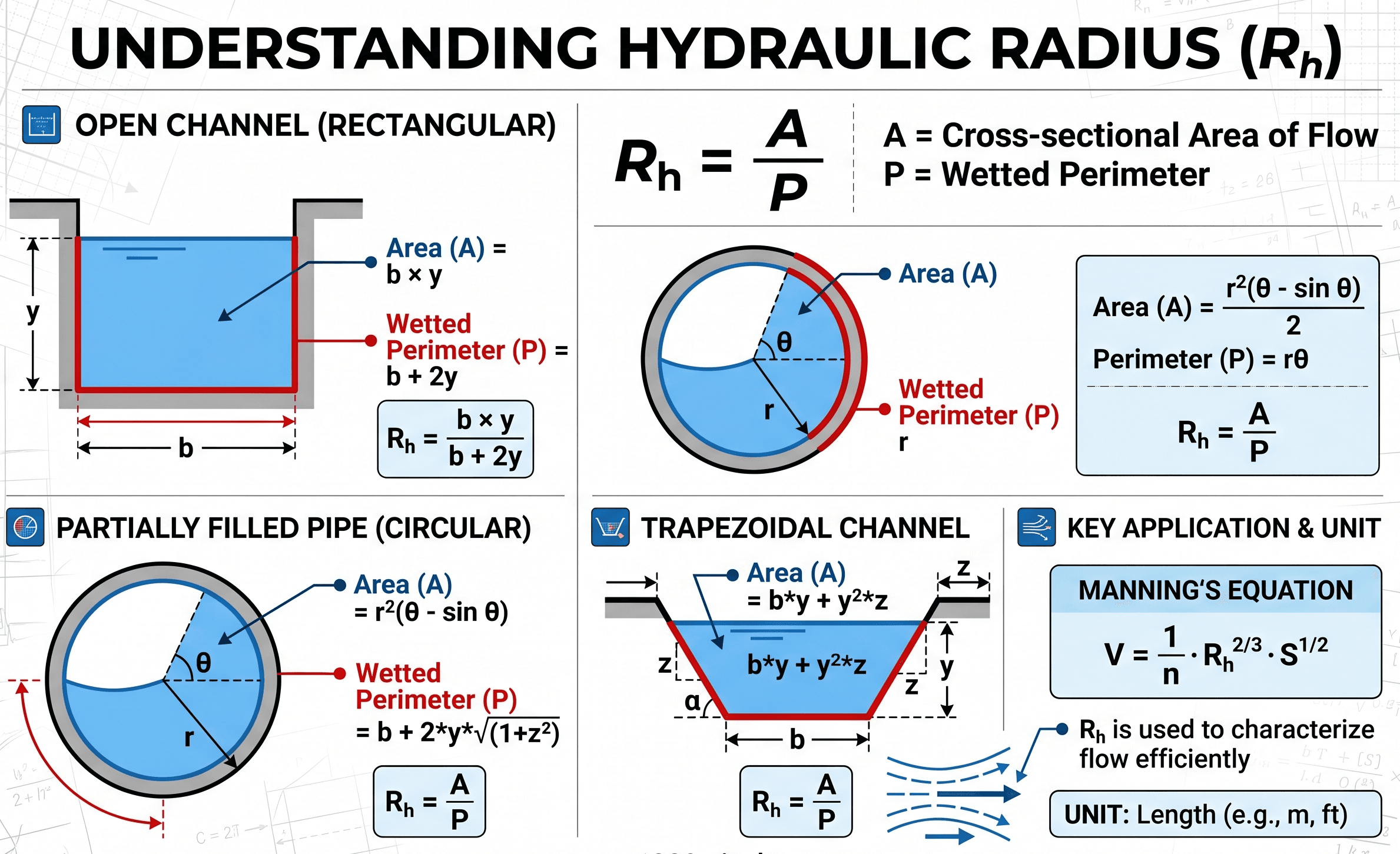
Notice the two quantities first: the blue flow area \(A\) and the boundary length touched by water, \(P_w\). Hydraulic radius increases when a section carries more area with less wetted perimeter, which usually means more efficient hydraulic conveyance.
The Hydraulic Radius Formula
The standard hydraulic radius equation divides the cross-sectional area of flow by the wetted perimeter. It is a geometric quantity, but it becomes powerful because it appears in flow-resistance equations such as Manning’s equation.
This form says that hydraulic radius is not just about how deep or wide the flow is. It depends on how much area is available to carry water compared with how much boundary is creating friction.
- \(R_h\) Hydraulic radius, usually in m or ft.
- \(A\) Cross-sectional flow area, usually in m² or ft².
- \(P_w\) Wetted perimeter, the length of boundary in contact with flowing water, usually in m or ft.
Area divided by length gives length, so hydraulic radius must have length units. If your result has units of area or is dimensionless, the setup is wrong.
Variables and Units
Hydraulic radius is unit-flexible, but the numerator and denominator must use the same length system. Use square meters with meters, or square feet with feet. Do not combine inches, feet, meters, and millimeters in the same calculation without converting first.
| Variable | Meaning | SI units | US customary units | Sanity-check note | Common mistake |
|---|---|---|---|---|---|
| \(R_h\) | Hydraulic radius | m | ft | For common channels, it is usually smaller than the flow depth unless the channel is very wide. | Treating it as equal to depth for every channel shape. |
| \(A\) | Flow area | m² | ft² | Use only the area actually occupied by flowing water. | Using the full pipe or channel area when the section is only partially full. |
| \(P_w\) | Wetted perimeter | m | ft | Include only the boundary in contact with water, not the free surface. | Including the top water surface as wetted perimeter in an open channel. |
If \(A\) is in square feet and \(P_w\) is in feet, \(R_h\) is in feet. If \(A\) is in square meters and \(P_w\) is in meters, \(R_h\) is in meters.
In a very wide rectangular channel, hydraulic radius approaches flow depth because the bed dominates the wetted perimeter and the sidewalls contribute relatively little.
Hydraulic Radius Quick Reference
Use this compact reference when you need to decide whether the equation fits the problem before performing a full calculation.
| Item | Quick answer |
|---|---|
| What it calculates | The ratio of flow area to wetted perimeter. |
| Required inputs | Cross-sectional flow area \(A\) and wetted perimeter \(P_w\). |
| Output | A length, such as meters or feet. |
| Best used when | You are analyzing open-channel flow, partially full conduits, full pipes, or Manning-type resistance relationships. |
| Do not use when | The cross section is unknown, the wetted boundary is changing rapidly, or the flow geometry is not representative of the actual condition. |
| Most important assumption | The selected flow area and wetted perimeter represent the same water surface and cross section. |
| Common mistake | Using total perimeter instead of wetted perimeter, especially in open channels. |
Hydraulic Radius for Common Shapes
Most hydraulic-radius problems are geometry problems first. Once the correct area and wetted perimeter are known, the equation is straightforward.
Full circular pipe
For a full circular pipe, the flow area is \(A=\pi D^2/4\) and the wetted perimeter is the full circumference, \(P_w=\pi D\). Substituting those into the main equation gives a useful shortcut.
Use this only for a pipe flowing full. A partially full circular pipe does not have \(R_h = D/4\), because both area and wetted perimeter change with depth.
Rectangular open channel
For a rectangular channel of bottom width \(b\) and flow depth \(y\), the water area is \(A=by\). The wetted perimeter includes the bottom and both wetted sidewalls.
Wide rectangular channel approximation
When the channel is much wider than it is deep, the sidewall contribution is small compared with the bed width. In that special case, hydraulic radius approaches the flow depth.
Trapezoidal channel
For a trapezoidal channel with bottom width \(b\), flow depth \(y\), and side slope \(z:1\) horizontal-to-vertical, the area and wetted perimeter are:
In open-channel flow, the water surface is not part of the wetted perimeter. Only the channel boundary touching the water belongs in \(P_w\).
Worked Example
Example: rectangular drainage channel
A rectangular concrete channel has a bottom width of \(b = 4.0\ \text{ft}\) and carries water at a depth of \(y = 1.5\ \text{ft}\). Estimate the hydraulic radius. Assume the channel section is prismatic and the flow depth is uniform at the section being evaluated.
First compute the flow area:
Next compute the wetted perimeter. The wetted perimeter includes the channel bottom and both sidewalls below the water surface:
Now divide area by wetted perimeter:
The hydraulic radius is approximately \(0.86\ \text{ft}\). That is less than the water depth of \(1.5\ \text{ft}\), which makes sense because the sidewalls add wetted perimeter and increase boundary resistance.
Compare the answer with the flow depth. For a narrow or moderately wide rectangular channel, \(R_h\) should be lower than \(y\). If your answer is larger than the depth, recheck the wetted perimeter.
Where Engineers Use Hydraulic Radius
Hydraulic radius is usually not the final answer by itself. It is a geometry input that helps engineers estimate resistance, conveyance, velocity, and capacity in hydraulic systems.
- Open-channel flow: Hydraulic radius is used with channel roughness and slope to estimate average velocity and discharge.
- Manning’s equation: \(R_h\) appears directly in the hydraulic-radius term, so errors in area or wetted perimeter affect flow estimates.
- Stormwater and drainage channels: Engineers use it to compare channel shapes and check whether a section can carry design flow.
- Culverts and partially full conduits: Hydraulic radius helps describe partially wetted flow areas when the conduit is not pressurized full.
- Full-pipe hydraulic analysis: For a full circular pipe, \(R_h=D/4\), which connects pipe geometry to resistance relationships.
In real channels, sediment, vegetation, debris, wall roughness, erosion, and nonuniform depth can change the effective flow area and wetted perimeter. A clean textbook section may not match the field condition.
Assumptions and Limitations
The hydraulic radius equation is exact for a chosen cross-section geometry, but the engineering result is only as good as the area and wetted perimeter used. The main assumptions are geometric and hydraulic.
- 1 The cross section is known and represents the flow condition being analyzed.
- 2 The flow area and wetted perimeter are taken at the same water depth.
- 3 The wetted perimeter includes only boundaries in contact with water, not the free surface.
- 4 For use in flow equations, the selected section is representative of the hydraulic reach.
What hydraulic radius does not include
Hydraulic radius does not include roughness by itself, does not directly calculate flow rate, and does not account for turbulence, sediment transport, bends, transitions, entrance losses, or rapidly varied flow. Those effects must be handled with the appropriate hydraulic equation or design method.
Do not use one hydraulic radius value for a reach where the water depth, geometry, vegetation, sediment, or boundary condition changes substantially from section to section.
Common Mistakes and Engineering Checks
Most hydraulic-radius errors come from using the wrong geometry rather than from the division itself. Before trusting the result, check the boundary definition and unit consistency.
- Including the free surface: The water surface is not a solid boundary and should not be counted as wetted perimeter.
- Using total perimeter: In partially full pipes or open channels, only the wetted portion counts.
- Using nominal pipe diameter: For pipes, use the actual inside diameter when computing area and wetted perimeter.
- Mixing units: Do not divide square meters by feet or square inches by meters.
- Assuming \(R_h = y\): This is only a wide-channel approximation, not a universal rule.
| Check item | What to verify | Why it matters |
|---|---|---|
| Units | \(A\) and \(P_w\) use the same base length unit. | The result should be a length, such as ft or m. |
| Boundary | Only solid surfaces in contact with water are counted. | Including the free surface makes \(P_w\) too large and \(R_h\) too small. |
| Magnitude | Compare \(R_h\) with water depth or pipe diameter. | An unrealistic value often reveals a geometry or unit mistake. |
| Flow condition | Check whether the pipe or channel is full, partially full, or open to atmosphere. | The correct area and wetted perimeter depend on the actual water level. |
For a full circular pipe, \(R_h = D/4\). For a very wide rectangular channel, \(R_h\) should be close to depth. These two limits are useful quick checks.
References and Source Notes
Hydraulic radius is a standard geometric quantity used throughout open-channel hydraulics and pipe-flow analysis. It commonly appears in fluid mechanics textbooks, open-channel flow references, stormwater manuals, and Manning-based design workflows.
- Fluid mechanics texts: Define hydraulic radius as \(A/P_w\) and connect it to flow resistance and conveyance.
- Open-channel hydraulics references: Use hydraulic radius in Manning-type velocity and discharge calculations.
- Design manuals: Often tabulate or compute hydraulic radius for channels, culverts, and stormwater conveyance sections.
The equation itself is geometric, so the main source of error is usually not the formula, but the selected cross section, depth, wetted boundary, or downstream hydraulic method.
Frequently Asked Questions
Hydraulic radius is the flow area divided by the wetted perimeter. It describes how efficiently a channel or conduit carries flow relative to the boundary in contact with the water.
For a full circular pipe, hydraulic radius equals one-fourth of the inside diameter: \(R_h = D/4\). This shortcut only applies when the pipe is flowing full.
No. Hydraulic radius is \(A/P_w\). In very wide rectangular channels it may be close to flow depth, but in narrow channels, pipes, and irregular sections it can be much different.
Hydraulic radius affects the resistance term in Manning’s equation. A larger hydraulic radius generally means a section conveys flow more efficiently for the same roughness and slope.
Summary and Next Steps
Hydraulic radius is a compact way to describe the relationship between flow area and wetted boundary. The formula \(R_h=A/P_w\) is simple, but it becomes important because it affects open-channel flow, Manning’s equation, pipe-flow resistance, and conveyance checks.
The most important engineering judgment is choosing the correct geometry. Use the actual water area, count only the boundary touched by water, keep units consistent, and check the result against known limits such as \(R_h=D/4\) for a full circular pipe.
Where to go next
Continue your learning path with related fluid mechanics equations and design checks.
-
Prerequisite: Continuity Equation
Learn how flow rate, area, and velocity connect before adding resistance terms.
-
Related: Reynolds Number
Check flow regime and understand why different hydraulic resistance equations apply under different conditions.
-
Next step: Hazen-Williams Equation
Move from hydraulic geometry into practical water-pipe head-loss and sizing calculations.