Key Takeaways
- Core idea: Power factor correction improves low power factor by reducing the reactive power a facility draws from the upstream AC system.
- Engineering use: Engineers use it to reduce kVA demand, free electrical capacity, lower current, improve voltage conditions, and avoid utility power factor penalties.
- What controls it: The main variables are real power in kW, existing power factor, target power factor, reactive power in kVAR, load variability, and harmonic distortion.
- Practical check: The common sizing formula is \( Q_c = P(\tan\theta_1 – \tan\theta_2) \), but capacitor banks should also be checked for harmonics, switching, overcorrection, and minimum-load operation.
Table of Contents
Introduction
Power factor correction improves low power factor by reducing reactive power demand in an AC electrical system. In most commercial and industrial power systems, it is done with capacitor banks that offset lagging reactive power from motors, transformers, and inductive loads so the same useful kW can be delivered with lower kVA, lower current, and fewer utility penalties.
Power Factor Correction Explained Visually
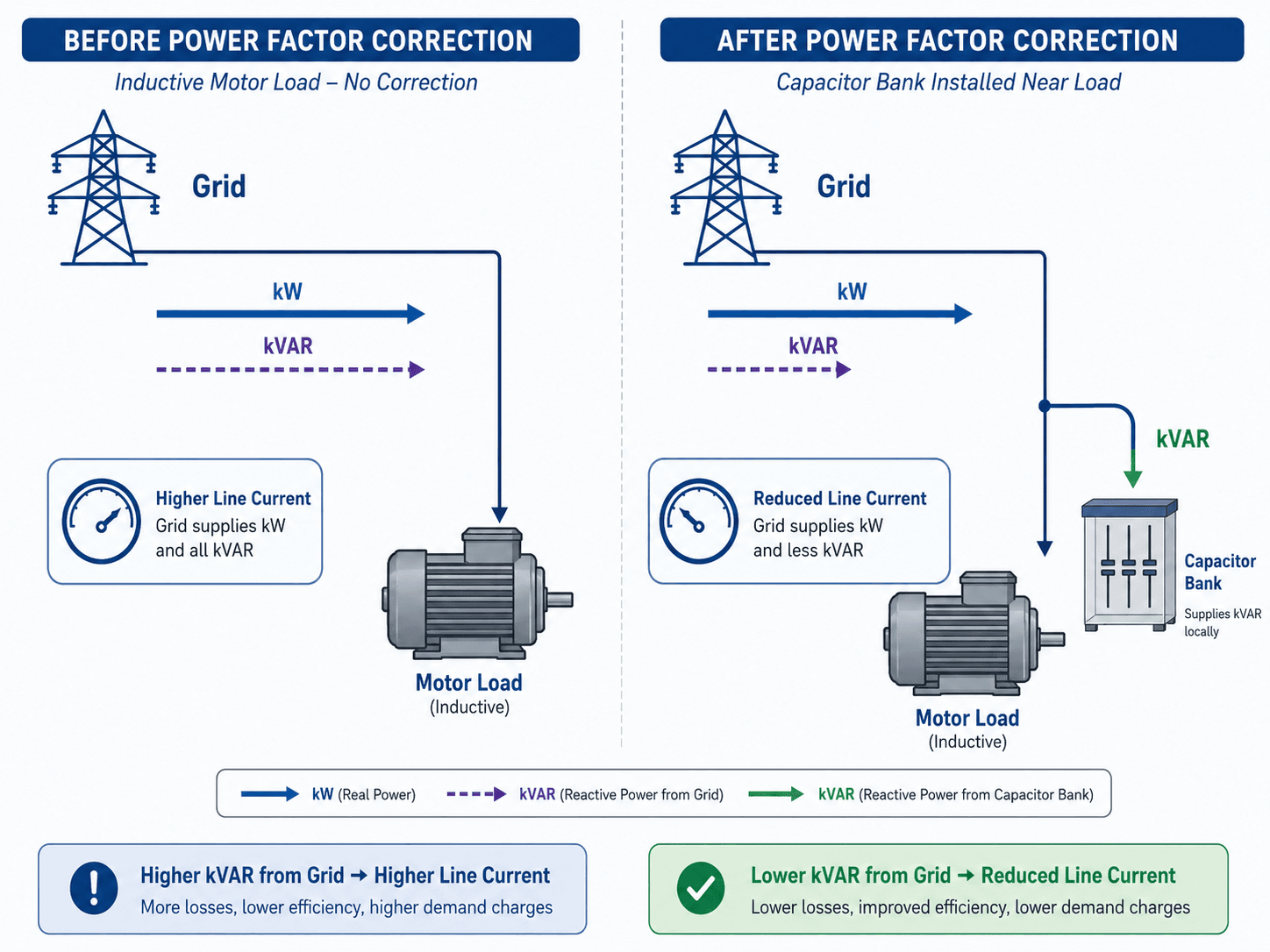
The key detail is that correction does not make the load do less work. It changes where reactive power is supplied from, reducing how much reactive current must travel through the upstream feeder, transformer, or utility system.
What is Power Factor Correction?
Power factor correction improves the ratio between real power and apparent power in an AC system. Real power, measured in kW, performs useful work such as turning a motor shaft, running a pump, powering a fan, or supporting an industrial process. Apparent power, measured in kVA, is the total capacity the system must supply. Reactive power, measured in kVAR, supports magnetic and electric fields but does not perform net useful work at the load.
A low power factor usually means the facility is drawing extra current for the same amount of useful work. That extra current loads conductors, transformers, generators, switchgear, and utility equipment. In a typical industrial plant, low power factor is often caused by lagging reactive demand from induction motors, transformers, welders, magnetic ballasts, and other inductive equipment.
The correction device supplies reactive power locally so the grid or upstream feeder does not need to supply as much of it. For most low-voltage and medium-voltage facilities, the correction device is a capacitor bank. For larger or more dynamic systems, engineers may also consider automatic capacitor banks, harmonic filters, synchronous condensers, static VAR compensators, or inverter-based reactive power control.
kW, kVA, kVAR, and the Power Triangle
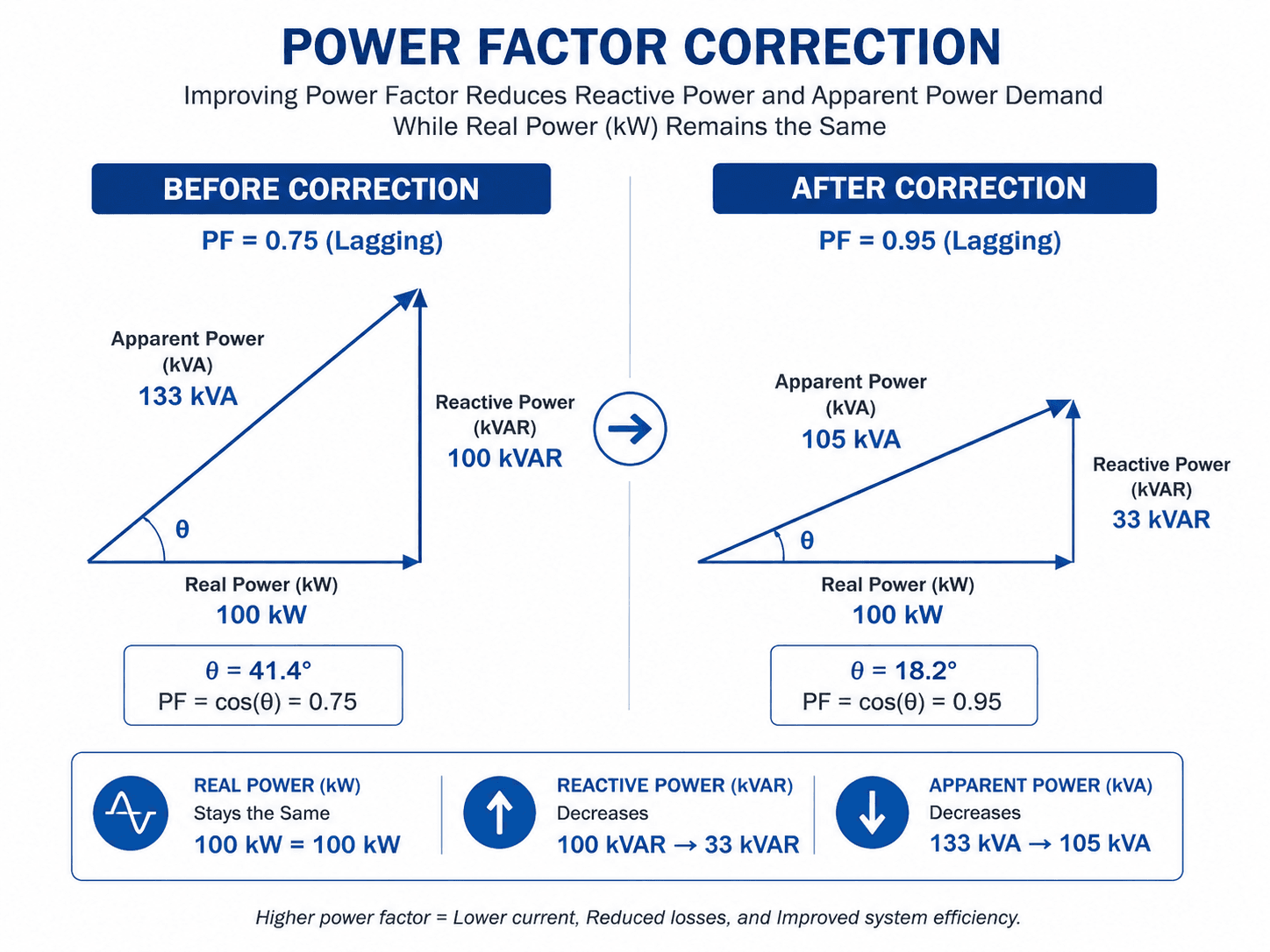
The power triangle is the cleanest way to understand why poor power factor increases electrical demand. The horizontal leg is real power \(P\), the vertical leg is reactive power \(Q\), and the diagonal is apparent power \(S\). Power factor is the ratio of real power to apparent power.
- P Real power in kW. This is the useful power converted into mechanical work, heat, light, or process output.
- Q Reactive power in kVAR. This supports magnetic or electric fields and increases current flow without adding net useful work.
- S Apparent power in kVA. This is the total power capacity the upstream system must carry.
- θ Phase angle between voltage and current. A larger angle usually means lower displacement power factor.
Lagging power factor
Most industrial correction problems involve lagging power factor, where current lags voltage because of inductive loads. Motors and transformers need magnetizing current to operate, and that magnetizing current creates reactive power demand.
Leading power factor
A leading power factor can occur when a system has too much capacitance for the connected load. This is one reason correction equipment is often staged, switched, or controlled automatically instead of being fixed at one constant kVAR value.
True power factor vs displacement power factor
The simple power triangle explains displacement power factor, which is based on the phase angle between voltage and current at the fundamental frequency. In systems with harmonic distortion, true power factor also accounts for waveform distortion. A facility can look corrected from a displacement power factor standpoint while still having poor true power factor because of nonlinear loads such as VFDs, rectifiers, UPS systems, and electronic power supplies.
How Capacitor Banks Correct Power Factor
Capacitors are used for power factor correction because they provide leading reactive power, which offsets the lagging reactive power drawn by inductive loads. The load still needs magnetizing reactive power to operate. Correction changes where that reactive power is supplied from, reducing how much must travel through the upstream feeder or utility system.
What changes after correction
After correction, the real power demand is usually unchanged, the reactive power from the upstream system decreases, the apparent power decreases, and line current drops. The lower current can reduce voltage drop, reduce \(I^2R\) losses, and release capacity in cables, transformers, breakers, and switchgear.
What does not change automatically
Power factor correction does not automatically make a motor, pump, fan, or process use less real power. If the mechanical load is the same, the kW requirement is still approximately the same. Cost savings usually come from demand charges, power factor penalties, released capacity, and reduced losses—not from reducing the useful kWh required by the load.
What Power Factor Correction Does and Does Not Do
A common misunderstanding is that improving power factor automatically reduces energy consumption. In reality, power factor correction mainly improves how the electrical system supplies the load. It can reduce current, kVA demand, voltage drop, and penalties, but it does not usually reduce the useful kWh required by the equipment.
| Claim | Accurate? | Engineering explanation |
|---|---|---|
| Reduces kVA demand | Yes | Lower reactive power reduces the apparent power drawn from the upstream system. |
| Reduces line current | Usually | For the same kW load, improved power factor reduces the current required from the source. |
| Reduces utility penalties | Often | Many commercial and industrial tariffs include low power factor penalties or kVA demand charges. |
| Reduces kWh used by the load | Not usually | The motor or process still needs about the same real power to do the same work. |
| Improves voltage drop | Often | Lower current can reduce voltage drop in feeders, transformers, and distribution paths. |
| Fixes harmonic problems | No | Capacitors can worsen harmonic resonance if they are not properly applied or detuned. |
If the utility bill includes a power factor penalty or kVA demand charge, correction can have a clear economic benefit. If the bill is only based on kWh and the system has no capacity or voltage issue, the savings case is usually weaker.
Power Factor Correction Formula
A common capacitor sizing approach is based on the difference between the existing reactive power and the target reactive power. First convert the existing and target power factors into angles, then calculate the change in kVAR.
In this equation, \(Q_c\) is the required capacitor bank size in kVAR, \(P\) is the real power in kW, \(\theta_1\) is the existing power factor angle, and \(\theta_2\) is the target power factor angle.
- Qc Capacitor size in kVAR. This is the reactive power the correction equipment should supply.
- P Real load power in kW, normally taken from metering, utility bills, load studies, or measured demand.
- PF1 Existing power factor before correction. This should come from measured data or utility billing records.
- PF2 Target power factor after correction. Many facilities aim near 0.95 to 0.98 rather than exactly 1.00.
| Power factor range | Typical meaning | Practical note |
|---|---|---|
| 1.00 | Unity power factor | Ideal mathematically, but not always the best practical target for a variable-load facility. |
| 0.95 to 0.98 | Common corrected range | Often a practical target range when utility rules and load behavior support it. |
| 0.85 to 0.90 | Moderate power factor | May be acceptable or penalized depending on the utility tariff and demand structure. |
| Below 0.80 | Low power factor | Often a strong candidate for review, especially in motor-heavy commercial or industrial facilities. |
Correcting to exactly 1.00 is not always the best design target. A slightly lower target can reduce the risk of leading power factor during light-load conditions and may still satisfy utility billing requirements.
Step-by-Step kVAR Sizing Example
Assume a facility has a 500 kW load operating at 0.78 lagging power factor, and the design target is 0.95 lagging power factor. The goal is to estimate the capacitor bank size needed to reduce upstream reactive demand.
| Step | Calculation | Engineering meaning |
|---|---|---|
| Existing angle | \(\theta_1 = \cos^{-1}(0.78) \approx 38.7^\circ\) | The existing load has a significant reactive component. |
| Target angle | \(\theta_2 = \cos^{-1}(0.95) \approx 18.2^\circ\) | The target condition has a smaller reactive component. |
| Required correction | \(Q_c = 500(\tan 38.7^\circ – \tan 18.2^\circ)\) | The capacitor supplies the difference between existing and target reactive power. |
| Estimated capacitor size | \(Q_c \approx 236 \text{ kVAR}\) | A practical design might use staged capacitor steps near this total after checking load variation and harmonics. |
The calculated result should be treated as a starting point, not an automatic purchase size. A facility with variable loads may need an automatic bank with multiple switched stages rather than one fixed 236 kVAR unit.
If the calculated correction is a large percentage of the facility load, verify the input power factor, billing interval, peak demand, and minimum-load condition before selecting equipment. Oversized fixed correction can create leading power factor when production is reduced.
Where Power Factor Correction Equipment Is Installed
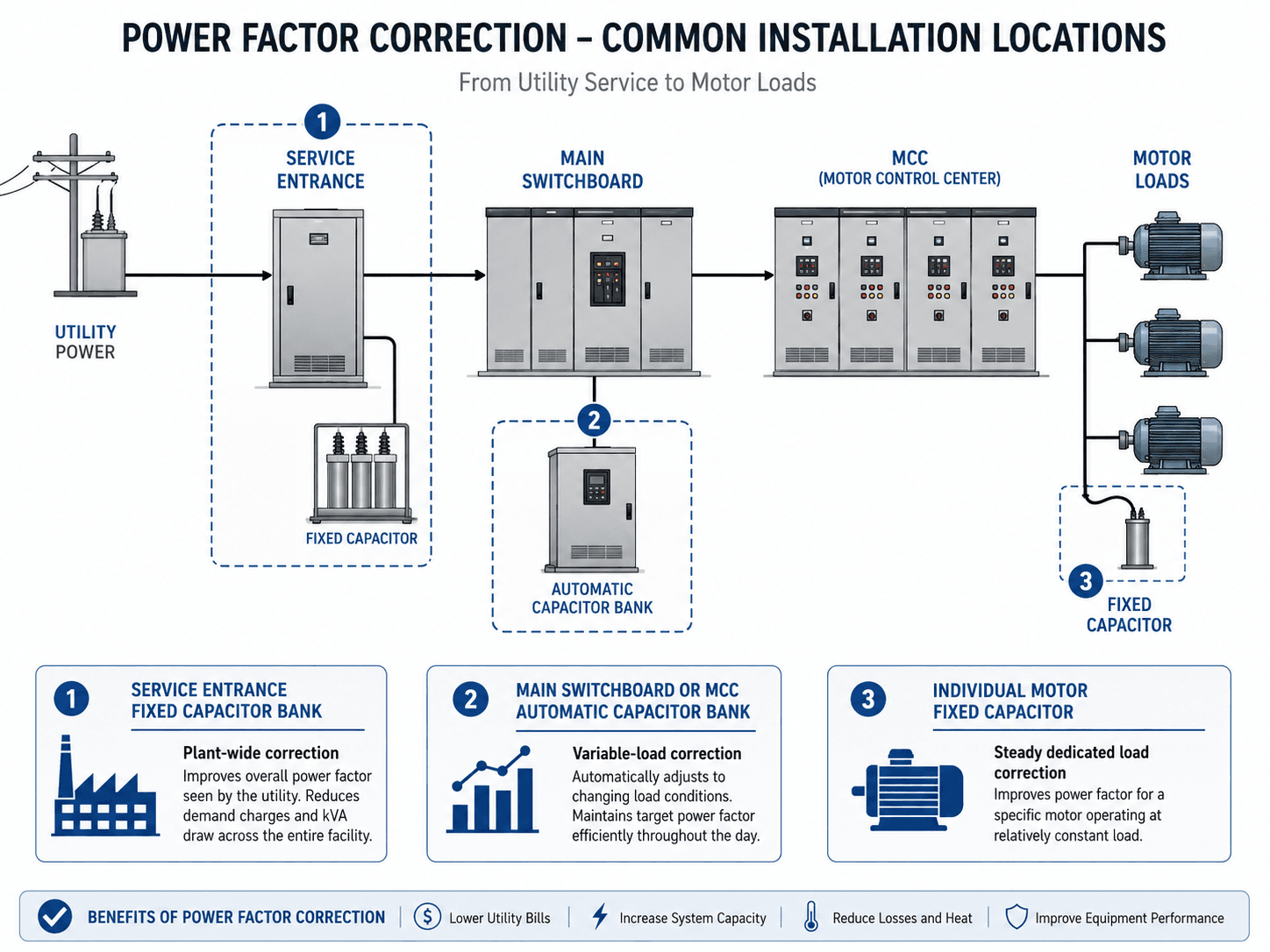
Correction equipment can be installed at the service entrance, main switchboard, motor control center, feeder, or individual motor. The best location depends on whether the goal is utility billing improvement, feeder current reduction, local voltage support, or dedicated motor correction.
| Installation location | Best use | Engineering tradeoff |
|---|---|---|
| Service entrance | Plant-wide power factor improvement as seen by the utility meter. | Can reduce penalties but may not reduce current in downstream feeders if correction is not located near the load. |
| Main switchboard or MCC | Variable-load correction using automatic switched capacitor stages. | Better for changing load patterns, but requires controls, switching devices, protection, and maintenance. |
| Individual motor | Dedicated correction for steady, frequently operated induction motors. | Can reduce local feeder current, but incorrect application can create overvoltage or overcorrection when the motor is disconnected. |
| Feeder-level correction | Targeted correction for a group of loads on a specific distribution path. | Useful when one process area drives the problem, but coordination with feeder switching and load variation is important. |
Fixed vs Automatic Power Factor Correction
The main design decision is whether the correction should stay fixed or adjust as the load changes. A fixed capacitor is simple, but it can be wrong for a facility with large daily load swings. An automatic capacitor bank uses staged steps and a controller to maintain a target power factor.
| Correction type | Use it when | Watch for |
|---|---|---|
| Fixed capacitor | The connected load is steady, predictable, and normally operates when the capacitor is energized. | Light-load overcorrection, incorrect motor switching arrangement, and lack of adaptability. |
| Automatic capacitor bank | The facility load changes throughout the day or different motors cycle on and off. | Step size, switching transients, contactor duty, controller settings, and maintenance access. |
| Detuned capacitor bank | The system has meaningful harmonic distortion from VFDs, rectifiers, UPS systems, or nonlinear loads. | Reactor tuning, thermal rating, harmonic current duty, and power quality verification. |
| Dynamic VAR compensation | Reactive power changes rapidly or voltage support must respond quickly. | Higher cost, controls complexity, and the need for a more detailed system study. |
When Power Factor Correction Is Worth It
Power factor correction is most valuable when low power factor creates a measurable cost, capacity, voltage, or equipment-loading problem. It is less compelling when the facility is not penalized for low power factor and does not have transformer, feeder, or voltage constraints.
| Condition | Correction is more likely worth it when | Correction may not be worth it when |
|---|---|---|
| Utility billing | The bill includes a low power factor penalty, kVA demand charge, or minimum PF requirement. | The customer is billed only for kWh with no demand or power factor charge. |
| Facility load type | Large induction motors, transformers, welders, compressors, pumps, or fans dominate the load. | Loads are small, intermittent, or mostly electronic with no utility penalty. |
| Capacity constraint | Transformers, feeders, breakers, or switchgear are near thermal or kVA limits. | The system has ample capacity and low current-related losses. |
| Voltage performance | Reactive current contributes to voltage drop or poor voltage profile under load. | Voltage is stable and the low PF does not create an operating issue. |
| Power quality | Harmonic distortion is low or the correction design includes detuning/filtering where needed. | Harmonics are significant and no power quality review has been performed. |
The strongest business case usually combines a utility penalty or kVA demand charge with a predictable motor-heavy load profile. The weakest case is a small customer with no PF-based billing and no capacity or voltage problem.
Senior Engineer Review Checklist for Power Factor Correction
A good correction design starts with the formula but does not stop there. The review should confirm that the equipment solves the actual billing or capacity problem without introducing leading power factor, resonance, switching problems, or maintenance issues.
Review the utility bill, measure the load profile, calculate the target kVAR, check harmonics, choose fixed or automatic correction, confirm protection and switching, then verify the corrected system under peak, normal, and light-load conditions.
| Review check | What to look for | Why it matters |
|---|---|---|
| Utility billing trigger | Power factor penalty, kVA demand charge, or minimum PF requirement. | Correction should target the actual cost driver, not just a textbook number. |
| Existing measured PF | Demand interval data, meter trends, or utility bill history. | One-time measurements can miss seasonal or process-driven load variation. |
| Minimum-load condition | Night, weekend, standby, or partial-production operating mode. | This is where oversized fixed capacitors are most likely to overcorrect. |
| Harmonic sources | VFDs, rectifiers, UPS systems, welders, large LED power supplies, or nonlinear process loads. | Capacitors can interact with system impedance and amplify harmonic problems. |
| Switching and protection | Step contactors, fuses, breakers, discharge resistors, controller settings, and enclosure rating. | Capacitor banks must be switched and protected as real electrical equipment, not just calculation outputs. |
| Verification after installation | Corrected PF trend, voltage profile, capacitor step operation, temperature, alarms, and utility bill response. | Commissioning confirms that the system improved operating conditions without creating new issues. |
Engineering Judgment and Field Reality
Field power factor problems rarely come from a perfectly steady load. Motors cycle, production lines change, HVAC demand moves with weather, and distributed generation can shift reactive power behavior. A correction design that looks right at peak load may be wrong during partial operation.
The utility meter location also matters. A service entrance capacitor bank may improve the power factor seen by the utility, but it may not reduce current in every downstream feeder. Conversely, a capacitor installed near a large motor can reduce local current but may not fully address plant-wide billing penalties if other loads still create low power factor.
The best correction location is tied to the problem being solved: utility charges, transformer capacity, feeder voltage drop, motor feeder current, or local equipment loading. One capacitor bank location is not automatically best for every objective.
When This Breaks Down
The simple power triangle is useful, but it can become misleading when the current waveform is distorted, when loads change quickly, or when capacitor banks interact with the rest of the electrical system. In those cases, engineers need measurement and system review beyond the basic kVAR formula.
- Nonlinear loads: VFDs, rectifiers, UPS systems, and electronic power supplies can create harmonic distortion, so true power factor may be worse than displacement power factor alone suggests.
- Resonance risk: Capacitors and system inductance can form resonant conditions that amplify harmonic voltages or currents.
- Light-load operation: A fixed capacitor sized for peak load can overcorrect the system when motors or process loads are off.
- Fast-changing loads: Staged capacitor banks may not respond fast enough for rapidly fluctuating reactive power demand.
- Incorrect objective: Correcting only at the service entrance may improve the utility bill but leave downstream voltage drop or feeder current issues unresolved.
Common Mistakes and Practical Checks
Most power factor correction mistakes come from treating the topic as a single capacitor sizing problem. The calculation is important, but the corrected system must also work across real operating conditions.
- Assuming PFC always saves kWh: The connected load usually consumes about the same real energy; savings come from lower losses, lower kVA demand, or avoided penalties.
- Ignoring harmonic distortion: Capacitor banks on harmonic-rich systems may require detuning or filtering.
- Correcting to 1.00 without a reason: This can increase the chance of leading power factor during low-load periods.
- Using peak load only: A plant with large load variation should be checked at normal and minimum operating conditions.
- Forgetting maintenance: Capacitors age, contactors wear, fuses operate, and ventilation issues can shorten equipment life.
Do not add a fixed capacitor bank to a facility with significant VFDs or nonlinear loads without reviewing harmonic conditions. The capacitor may correct displacement power factor while creating a power quality problem.
Useful References and Design Context
Power factor correction sits between electrical theory, utility billing, and practical power system design. A useful reference should explain why low power factor increases system current and capacity demand, while still leaving room for project-specific engineering review.
- U.S. Department of Energy: Reducing Power Factor Cost connects power factor to utility demand charges, current flow, distribution capacity, voltage drop, and practical economic drivers for correction projects.
- Project-specific criteria: Utility tariffs, service requirements, plant load profiles, owner standards, and equipment ratings should control the final correction target and equipment selection.
- Engineering use: Engineers use references like this alongside metering, load studies, harmonic measurements, equipment data, and commissioning checks to decide whether correction is technically and economically justified.
Frequently Asked Questions
Power factor correction is the process of improving low power factor by reducing the reactive power drawn from the utility or upstream electrical system. In most commercial and industrial systems, this is done with capacitor banks that offset lagging reactive demand from motors, transformers, and other inductive loads.
Power factor correction usually does not reduce the real energy consumed by the load itself. A motor still needs roughly the same kW to do the same mechanical work. Savings usually come from lower utility penalties, lower kVA demand, reduced current, and lower distribution losses in conductors and transformers.
A common sizing method is to calculate the existing reactive power from the load kW and existing power factor, calculate the target reactive power from the target power factor, and subtract the two. The required capacitor size is commonly estimated as kVAR = kW × (tan θ1 − tan θ2), where θ1 and θ2 are the existing and target power factor angles.
Overcorrection can push the system toward a leading power factor, which may cause voltage rise, nuisance switching, poor utility interaction, or resonance concerns. For that reason, many systems target a practical range such as 0.95 to 0.98 rather than trying to force power factor to exactly 1.00 under all load conditions.
Yes. Harmonics from variable frequency drives, rectifiers, UPS systems, LED drivers, and other nonlinear loads can interact with capacitor banks and system inductance. In those systems, engineers may need harmonic measurements, detuned capacitor banks, filters, or a more detailed power quality review before adding correction equipment.
For most residential customers, power factor correction is not usually worth adding because homes are typically billed for real energy use in kWh rather than low power factor penalties or kVA demand. It is much more common in commercial and industrial facilities with larger motors, transformers, and utility demand charges.
Summary and Next Steps
Power factor correction improves how efficiently an AC power system uses apparent power by reducing unnecessary reactive power flow. In practical terms, it helps the same real load operate with lower upstream current, lower kVA demand, and better use of transformers, conductors, switchgear, and utility capacity.
The key workflow is to identify the existing power factor, choose a practical target, estimate the needed kVAR, select the right correction location, and check the design against load variation, harmonics, switching, overcorrection, and maintenance realities.
Where to go next
Continue your learning path with related Turn2Engineering resources.
-
Voltage Regulation
Learn how voltage changes with load, current, feeder impedance, taps, and reactive power support.
-
Load Flow Analysis
See how engineers study bus voltage, reactive power flow, equipment loading, and capacitor bank impacts in network models.
-
Power System Efficiency
Review how losses, current, equipment loading, and operating decisions affect overall system performance.