
Direct Answer
The main power system components are generators and inverters, transformers, transmission lines, substations and busbars, distribution feeders, switching devices, protective relays, current and voltage transformers, voltage-control equipment, grounding systems, monitoring and control systems, energy storage, and electrical loads.
These components work together to generate power, change voltage, move electricity through the network, isolate faults, control voltage and reactive power, measure operating conditions, and deliver usable electrical energy to customers. This page is the system-level map; each major component links to a dedicated Turn2Engineering guide for deeper study.
Major Power System Components and Their Functions
The fastest way to understand a power system is to connect each component to the job it performs and then follow the link to the detailed equipment or system guide when you need more depth.
Identify whether the component generates, transforms, carries, switches, protects, controls, measures, grounds, stores, or consumes power.
Voltage class, continuous current, MVA or kVA, fault duty, insulation, control/protection requirements, environment, and reliability role.
Open the linked component page for construction, ratings, operating principles, protection, failure modes, and selection guidance.
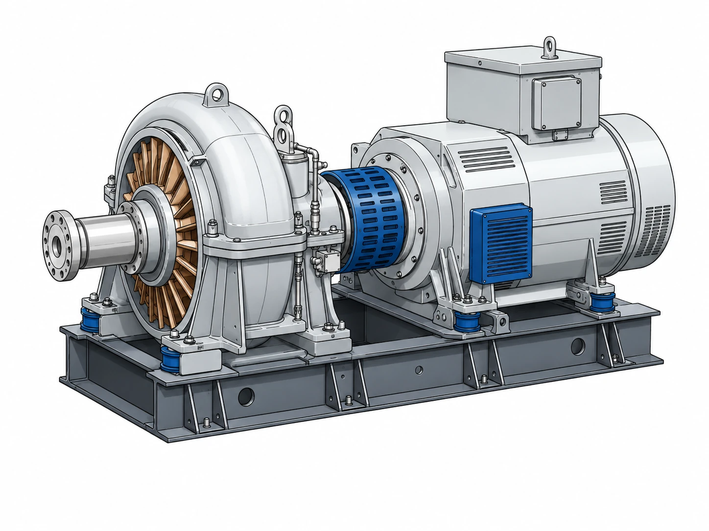
Generator
Converts mechanical input into electrical power. Key checks include MW, MVA, terminal voltage, power factor, reactive capability, grounding, protection, and dynamic/fault parameters.

Grid-Connected Inverter
Interfaces solar, battery, and other inverter-based resources with the grid. Controls can influence voltage, reactive power, fault response, ride-through behavior, and interconnection protection.

Transformer
Transfers electrical power between voltage levels. Important parameters include MVA or kVA, voltage ratio, impedance, vector group, tap range, insulation, cooling, and grounding relationship.
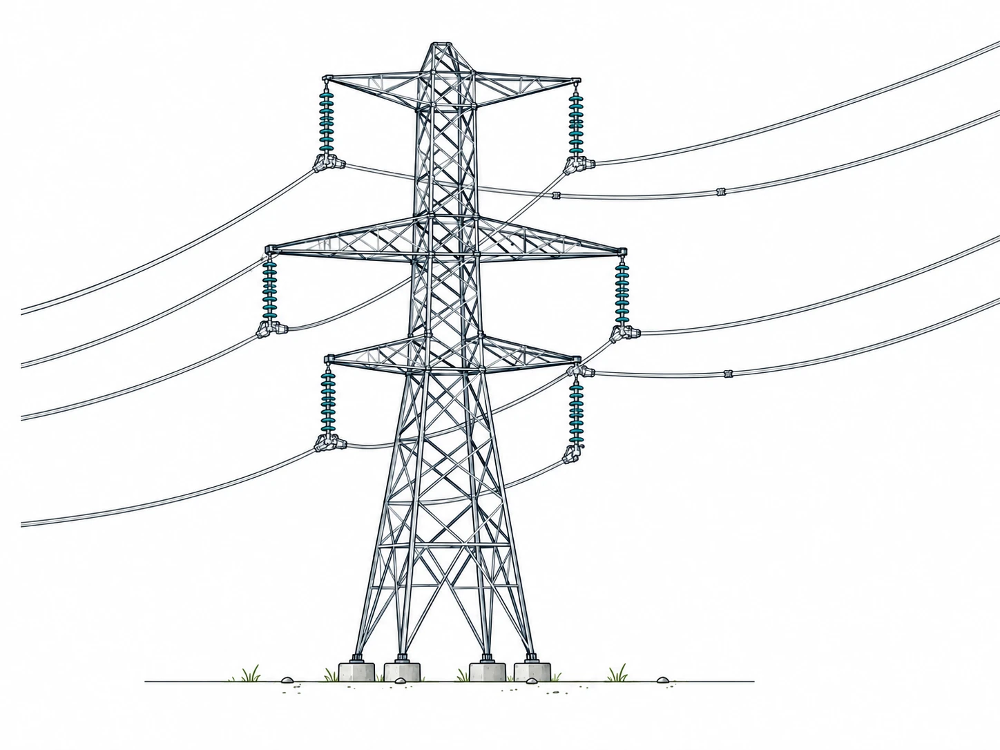
Transmission Line
Moves bulk power through the high-voltage network. Engineers check conductor type, ampacity, resistance, reactance, capacitance, clearances, thermal limits, and protection.
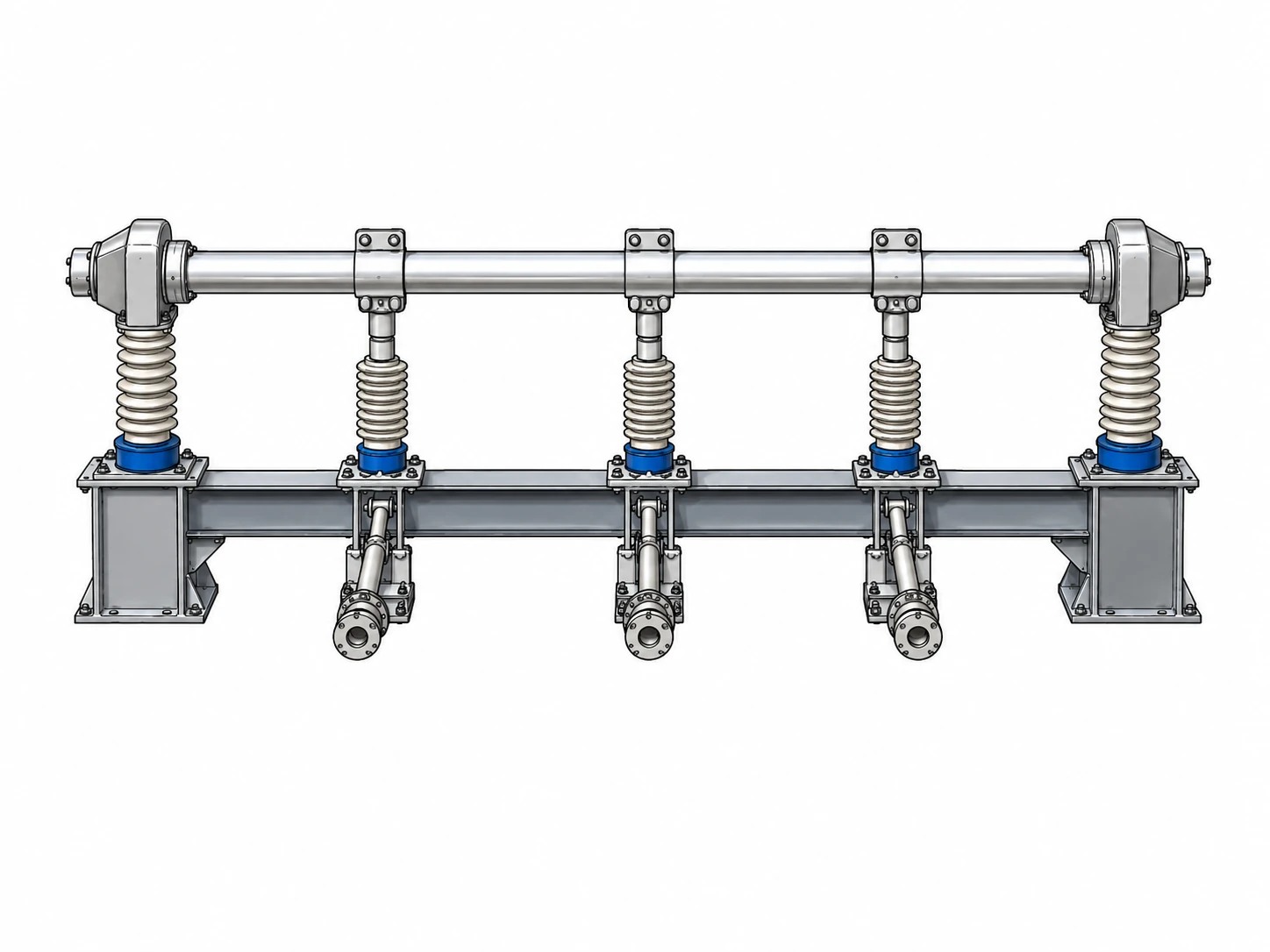
Busbar
Provides a common electrical node connecting multiple circuits. Bus current rating, fault withstand, physical arrangement, protection zone, and maintainability are key concerns.
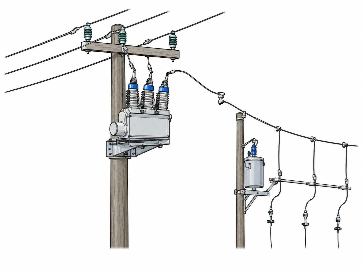
Distribution Feeder
Delivers power from a distribution substation toward customer loads. Loading, voltage drop, reliability, fault coordination, conductor/cable rating, and load growth matter.

Circuit Breaker
Carries normal current and interrupts specified switching or fault current. Rated voltage, continuous current, interrupting duty, short-time withstand, operating time, and mechanism are critical.
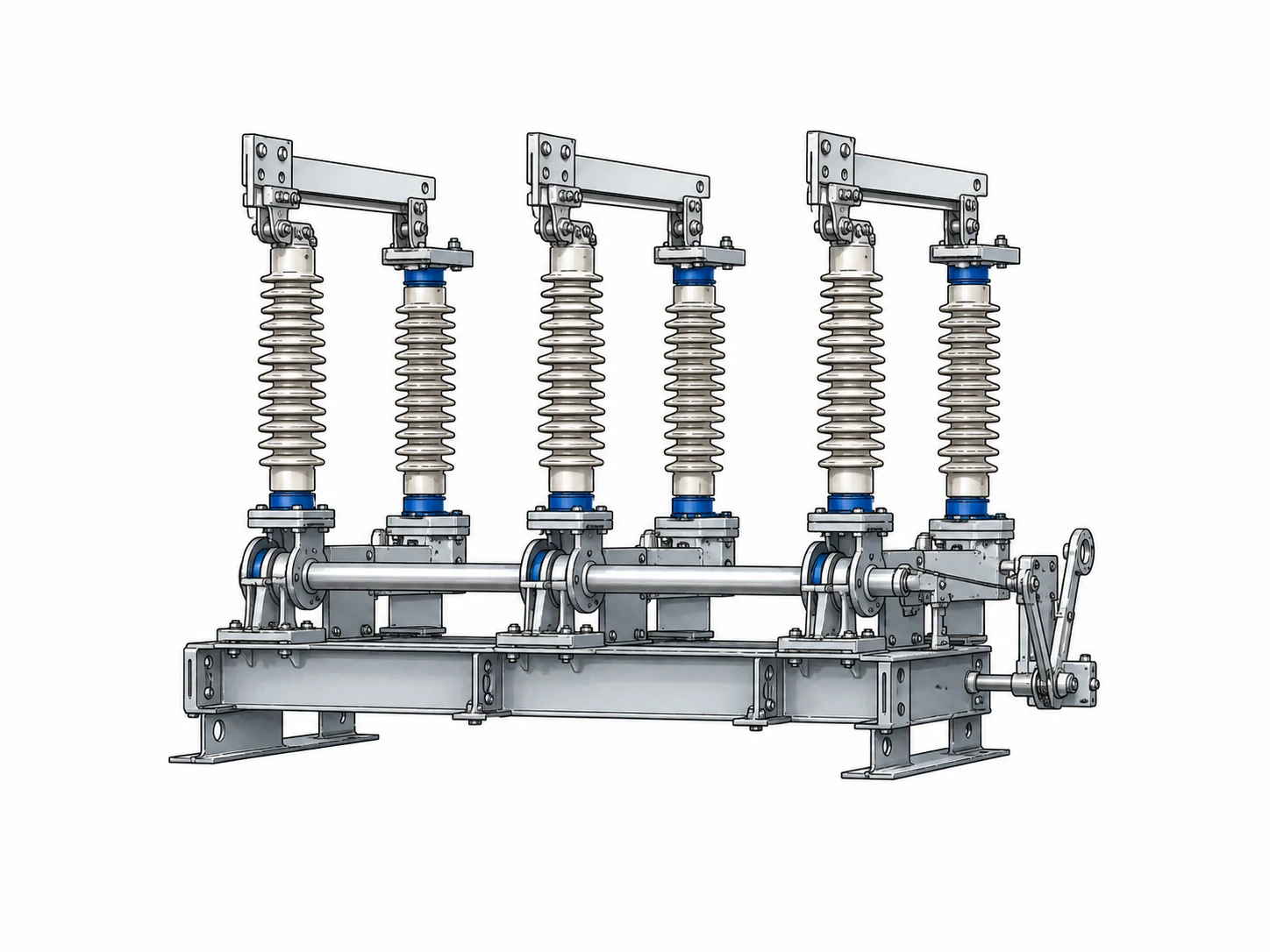
Disconnector
Provides circuit isolation and visible separation where applicable. Engineers must understand its switching capability, interlocks, operating sequence, and maintenance boundary.
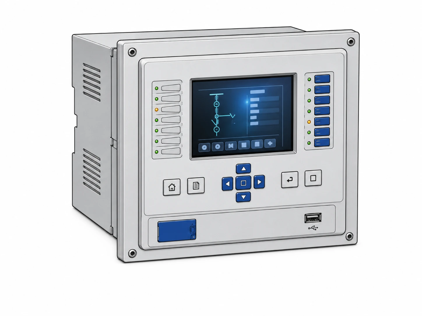
Protective Relay
Uses measured electrical quantities and logic to detect abnormal conditions and initiate protective action. Functions, settings, CT/VT inputs, timing, communications, and coordination matter.

Current Transformer (CT)
Reproduces primary current at a scaled level for protection and metering. Ratio, polarity, burden, accuracy class, saturation performance, and insulation determine suitability.

Voltage Transformer (VT/PT)
Scales system voltage for protection, metering, synchronizing, and controls. Ratio, accuracy, grounding, burden, and fuse/protection arrangements must match the application.
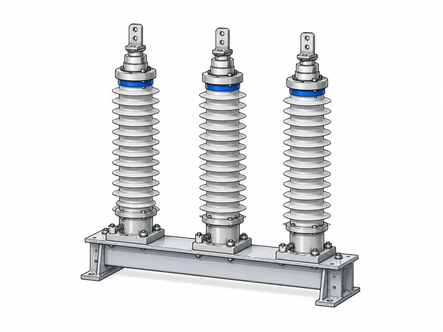
Surge Arrester
Limits transient overvoltage at protected equipment. Continuous operating voltage, protective level, energy duty, placement, and insulation coordination are important.
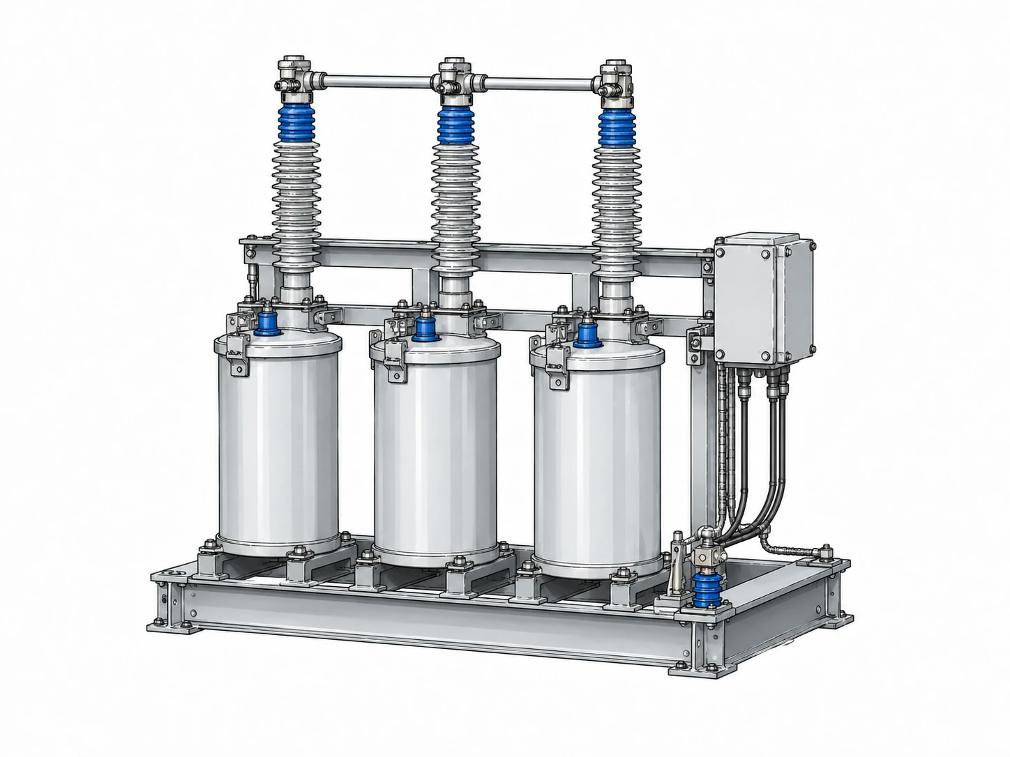
Capacitor Bank
Supplies reactive power to support voltage or improve power factor. kVAR/MVAR, voltage, switching steps, harmonic environment, protection, and switching duty control selection.
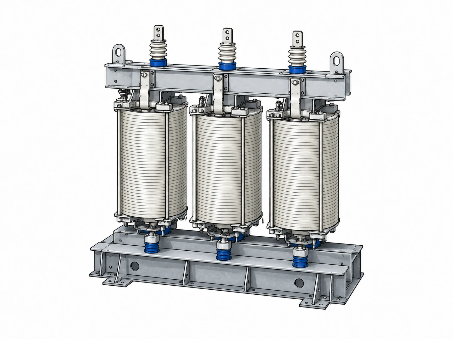
Reactor
Provides inductive reactance for reactive-power control, current limiting, or other network applications. Rating, connection, insulation, losses, harmonics, and protection matter.

SCADA, IEDs, and RTUs
Measure, supervise, automate, alarm, communicate, and record system operation. Availability, time synchronization, data quality, cybersecurity, and fallback behavior are key concerns.
A power-system drawing that shows only generation, transmission, distribution, and loads is incomplete for engineering use. Protection, switching, measurement, grounding, control power, communications, and maintenance isolation are part of how the real system operates.
Primary vs. Secondary Power System Equipment
Primary equipment directly generates, transforms, carries, switches, compensates, stores, or consumes electrical power; secondary systems measure, protect, control, automate, communicate with, and supervise that primary equipment.

Primary Equipment
Generators, inverters, transformers, lines, cables, busbars, breakers, disconnectors, feeders, capacitors, reactors, storage interfaces, and loads form the main power path.
Measurement & Protection
CTs, VTs/PTs, protective relays, meters, disturbance recorders, trip circuits, and breaker-failure logic determine how the system detects and clears abnormal conditions.
Control & Communication
Station batteries, IEDs, RTUs, PLCs, SCADA, plant controllers, communication networks, and time synchronization make the system observable and controllable.
One of the most useful protection chains to recognize is CT/VT → relay → trip circuit → circuit breaker → fault isolation. A large transformer or breaker can be mechanically healthy while a failed station battery, incorrect relay setting, CT saturation, wiring error, or lost communication channel prevents the system from operating correctly.
U.S. Department of Energy grid resources describe the electric grid as an interconnected physical and digital system that includes transmission and distribution equipment, transformers, sensors, software, and communications: U.S. Department of Energy — Electric Grids.
How Power System Components Work Together From Source to Load
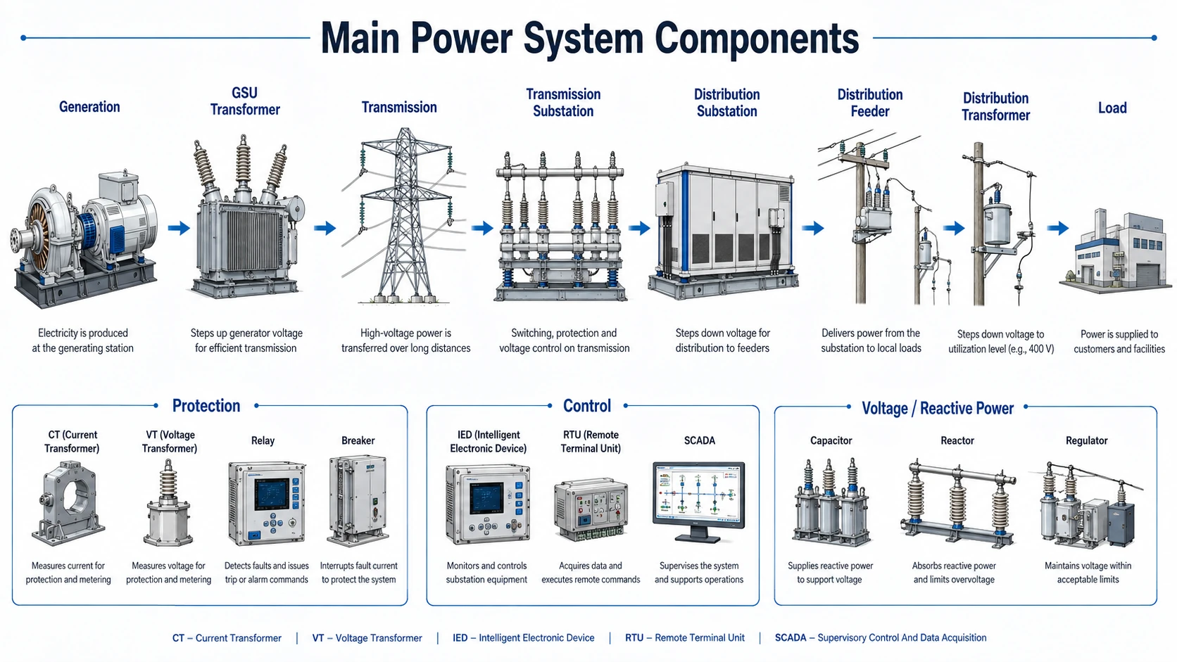
Electricity is generated or injected into the network, transformed to appropriate voltage levels, moved through transmission and distribution networks, switched and protected at substations and along feeders, and finally delivered to loads.
Generation and Voltage Transformation
Conventional generators and inverter-based resources inject real power and, depending on equipment and control capability, reactive power. Generator step-up transformers raise voltage before bulk transfer. For a balanced three-phase system, the relationship between real power, line voltage, line current, and power factor is:
For the same real-power transfer and power factor, increasing line-to-line voltage reduces line current. That can reduce conductor losses and voltage drop, but higher voltage also increases insulation, clearance, switching, surge-protection, and substation requirements.
Transmission, Substations, and Distribution
Power transmission moves bulk power between generators, substations, and load areas. Substations connect circuits, switch and isolate equipment, transform voltage, measure system quantities, and coordinate protection. Distribution systems then deliver power locally through feeders, regulators, reclosers, fuses, capacitor banks, distribution transformers, services, and meters.
Modern Grid Components
Solar inverters, battery energy storage, microgrids, smart meters, automated switches, digital relays, communications, and advanced control systems can change power-flow direction, fault-current characteristics, voltage control, protection coordination, and operating visibility. These newer devices extend the traditional power system rather than replacing its core functions.
How to Identify Power System Components on a One-Line Diagram
Read a one-line diagram in layers: locate sources, mark voltage transitions, trace the power path, trace the fault and grounding path, identify protection zones, and verify isolation and control-power paths.

-
Locate every source.
Identify utility connections, generators, inverters, battery systems, and alternate feeds.
-
Mark each voltage level.
Find transformers and record nominal voltages, ratios, tap ranges, and utilization voltages.
-
Trace the primary power path.
Follow buses, lines, cables, breakers, feeders, service equipment, and loads.
-
Trace fault and grounding paths.
Identify source contributions, grounding methods, neutral paths, and devices that must withstand or interrupt fault current.
-
Trace protection zones.
Match CTs/VTs to relays, relays to trip circuits, and trip circuits to the breakers that isolate each protected zone.
-
Check isolation and contingency paths.
Determine what can be maintained safely and what remains energized if a source, line, transformer, or bus section is unavailable.
Do not stop after confirming that power can reach the load. Confirm that the system can also clear faults, regulate voltage, isolate equipment, survive credible outages, communicate status, and be maintained safely.
Where Power System Components Appear in the Grid
The same equipment types can appear at generation plants, transmission substations, distribution substations, feeders, industrial facilities, and customer sites, but their ratings and operating roles change with voltage level and system purpose.
Substation Components
A substation is an equipment group rather than one device. Typical components include power transformers, busbars, circuit breakers, disconnectors, CTs, VTs/PTs, surge arresters, capacitor banks or reactors, protective relays, station batteries, control panels, SCADA equipment, communications, and a grounding grid.

Go deeper with Substations, Switchgear, Circuit Breakers, and Busbars.
Distribution System Components
Distribution systems commonly include primary feeders, overhead conductors or underground cables, switches, reclosers, sectionalizers, fuses, voltage regulators, capacitor banks, distribution transformers, secondary conductors, service equipment, meters, and customer loads.

Go deeper with Power Distribution and Distribution Lines.
Protection and Control Components
Protection and control systems supervise primary equipment. A typical fault-clearing sequence is measurement → protection logic → trip circuit → interrupting device → isolation → event/status reporting.

Go deeper with Protective Relays, Overcurrent Protection, Differential Protection, and Transmission Line Protection.
Power System Equipment Ratings and Selection Checks
A component is suitable only when its ratings and operating characteristics match the system conditions established by load, fault, protection, grounding, reliability, environmental, and project requirements.

| Component | Important ratings / parameters | What can make it unsuitable | Detailed guide |
|---|---|---|---|
| Transformer | MVA/kVA, voltage ratio, impedance, vector group, tap range, insulation, cooling | Overload, unacceptable voltage, excessive fault duty, wrong connection/grounding, inadequate insulation or cooling | Transformers |
| Circuit breaker | Rated voltage, continuous current, interrupting duty, making duty, short-time withstand, operating time | Available fault current exceeds interrupting or withstand capability, or switching duty exceeds rating | Circuit Breakers |
| Transmission line / feeder | Voltage, conductor/cable type, ampacity, R/X parameters, thermal limit, insulation, sag/clearance | Thermal overload, excessive voltage drop/loss, insufficient clearance, insulation or stability limitation | Transmission Lines |
| Current transformer | Ratio, polarity, burden, accuracy class, saturation performance, insulation | Incorrect ratio, excessive burden, saturation during faults, polarity/wiring error | Protective Relays |
| Generator | MW, MVA, voltage, power factor, reactive limits, grounding, dynamic/fault parameters | Capability-curve violation, inadequate voltage/reactive support, protection or stability limitation | Generators |
| Capacitor bank | kVAR/MVAR, voltage, step size, switching duty, insulation, harmonic environment | Overvoltage, harmonic resonance, switching stress, unsuitable protection or control sequence | Capacitors |
Swipe horizontally to view all table columns.
What Controls Component Selection?
Voltage level sets insulation and equipment class. Continuous current and MVA set thermal loading. Fault current sets interrupting and withstand requirements. Grounding changes fault paths and protection sensitivity. Reliability affects redundancy and bus arrangement. Environment affects insulation, enclosure, cooling, corrosion, contamination, altitude, flooding, wildlife, and maintenance requirements.
Do not select power-system equipment from normal load current alone. A breaker can carry the load yet be underrated for fault current, and a transformer can have sufficient MVA while still having the wrong impedance, vector group, tap range, grounding relationship, insulation level, or cooling for the application.
Which Engineering Study Checks Each Power System Component?
No single engineering study verifies every component. Load flow, short-circuit, fault, protection, stability, and power-quality studies answer different questions about how the same equipment will behave.
| Question | Study | Components most affected | Typical outputs |
|---|---|---|---|
| Are voltage, MW/MVAR flow, loading, and losses acceptable? | Load Flow Analysis | Generators, transformers, lines, feeders, buses, capacitors, loads | Bus voltage, MW/MVAR flow, equipment loading, losses |
| Can equipment withstand and interrupt available fault current? | Short-Circuit Analysis | Breakers, switchgear, buses, transformers, cables, protection | Fault current, equipment duty, source contributions |
| How do balanced and unbalanced faults behave? | Fault Analysis | Sources, transformers, lines, sequence networks, grounding, relays | Fault current, sequence quantities, fault voltages |
| Will protective devices operate selectively? | Protection / Coordination | Relays, breakers, fuses, reclosers, CTs and VTs | Settings, operating times, coordination margins, protection-zone behavior |
| Will the system recover acceptably after a disturbance? | Power System Stability | Generators, inverters, controls, transmission network, large loads | Frequency, voltage, rotor/control response, damping, stability limits |
| Are harmonics, sags, swells, imbalance, or transients acceptable? | Power Quality | Converters, capacitors, transformers, cables, sensitive loads | Distortion, event levels, harmonic spectrum, mitigation targets |
Swipe horizontally to view all table columns.
Worked Example: How Voltage Changes Power System Component Requirements
Compare current for a 10 MW three-phase power transfer
Assume a balanced three-phase system transfers 10 MW at a power factor of 0.95. Ignore losses for this simple comparison. The purpose is to show why voltage transformation changes current and therefore changes the requirements of many other components.
Write the three-phase current equation
Solve the balanced three-phase real-power equation for line current.
Use watts for P and volts for V_LL to obtain current in amperes.
Calculate current at each voltage
Compare the same power transfer at 13.8 kV and 69 kV.
Interpret the component impacts
Translate the electrical result into system-level equipment consequences.
Lower current can reduce conductor heating, current-related voltage drop, bus current duty, and current-transformer primary rating for the same transferred power.
Higher voltage increases insulation, clearance, switchgear, breaker, surge-protection, transformer, and substation requirements.
69 kV is exactly five times 13.8 kV, so current should be one-fifth when the other terms are unchanged.
This simplified comparison ignores losses, reactive-flow changes, equipment impedance, line charging, and project-specific design limits.
Use Load Flow Analysis to evaluate voltage, loading, and power flow for an actual network.
Power System Components Engineering References
The sources below support the system-level description of generation, transmission, distribution, substations, grid equipment, monitoring, controls, and bulk-power reliability. Equipment selection and final design still require current project-specific standards, utility requirements, manufacturer data, and applicable jurisdictional requirements.
- U.S. Department of Energy — Electric Grids System-level description of the electric grid, including transmission, distribution, transformers, sensors, software, communications, and generation resources.
- U.S. Department of Energy — Electricity Grid Backgrounder Background on generation, transmission, substations, transformers, distribution feeders, protection, and grid-control concepts.
- U.S. Department of Energy — Grid Systems and Components Grid modernization context for physical hardware, sensors, controls, software, and integrated grid technologies.
- Federal Energy Regulatory Commission — Reliability Explainer Bulk-power-system reliability context and the role of generation and transmission facilities within the interconnected system.
Frequently Asked Questions
What are the main components of a power system?
The main components include generators and inverters, transformers, transmission lines, substations, busbars, distribution feeders, circuit breakers and other switching devices, protective relays, CTs and VTs, voltage-control and grounding equipment, monitoring/control systems, energy storage where installed, and electrical loads.
What are primary and secondary components in a power system?
Primary equipment directly handles electrical power, such as generators, transformers, lines, buses, breakers, feeders, capacitors, reactors, storage interfaces, and loads. Secondary systems measure, protect, control, automate, communicate with, and supervise the primary equipment.
What components are normally found in a substation?
A substation may include transformers, busbars, circuit breakers, disconnectors, CTs, VTs/PTs, surge arresters, capacitor banks or reactors, protective relays, station batteries, control panels, SCADA equipment, communications, and a grounding grid. The exact arrangement depends on the substation’s function and voltage class.
Which study checks power system component ratings?
No single study checks every rating. Load flow evaluates voltage and steady-state loading; short-circuit analysis evaluates fault duty; protection studies evaluate selective operation; stability studies examine dynamic response; and power-quality studies evaluate waveform and voltage disturbances.
Summary and Next Step
The best way to understand power system components is to view them as one coordinated network: sources generate power, transformers change voltage, lines and feeders move it, substations connect and switch it, protection isolates faults, controls regulate and monitor operation, grounding establishes safe fault/reference paths, and loads use the energy.
Once you can identify the components and their functions, the next step is to understand the engineering studies used to determine whether those components are correctly loaded, rated, protected, and coordinated.