Key Takeaways
- Core idea: A substation is a power system node that transforms voltage, switches circuits, protects equipment, measures power, and controls how electricity moves through the grid.
- Engineering use: Substations connect transmission lines, distribution feeders, power plants, renewable collector systems, industrial loads, and utility control systems.
- What controls it: Voltage level, fault current, bus arrangement, protection zones, equipment ratings, grounding, space, reliability requirements, and maintenance access shape substation design.
- Practical check: A substation is not just a transformer yard; protection, control power, grounding, switching access, and fault isolation are just as important as voltage transformation.
Table of Contents
Introduction
A substation is a high-voltage power system facility that connects parts of the grid and helps transform voltage, switch circuits, isolate faults, measure power, and control electricity flow. In practical power systems engineering, substations are the controlled handoff points between generation, transmission, distribution, industrial loads, and renewable energy facilities.
How Power Flows Through a Substation
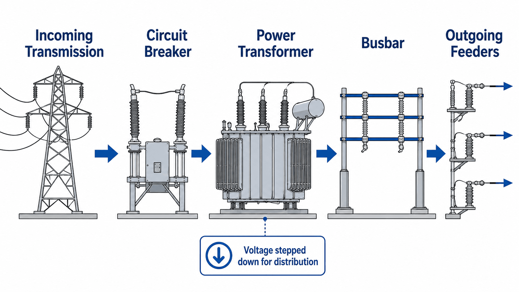
Notice that the transformer is only one part of the system. The breaker, busbar, feeder equipment, protection devices, and control systems determine whether the substation can safely route and isolate power during normal and abnormal conditions.
What Is a Substation?
A substation is an electrical facility where power circuits are connected, separated, transformed, measured, protected, and controlled. It may step voltage up for long-distance transmission, step voltage down for distribution, switch power between circuits, isolate a faulted section, or connect a generator, solar plant, wind farm, industrial facility, or utility network to the grid.
The most common public image of a substation is a fenced yard with transformers, steel structures, insulators, and overhead conductors. From an engineering perspective, the more important idea is that a substation creates a controlled electrical node. It defines where circuits meet, where protection zones begin and end, where voltage changes, and where operators can monitor and control grid equipment.
Do not define a substation only by the transformer. Some substations have major transformers, while switching stations may have no voltage transformation at all. The defining feature is controlled interconnection, switching, protection, measurement, grounding, and grid operation.
What Substations Do in the Power Grid
Substations are placed wherever the power system needs a controlled interface between circuits. That interface may be between two transmission lines, a transmission system and a distribution system, a power plant and the grid, a renewable collector system and a utility interconnection, or a utility feeder and a large industrial customer.
| Substation function | What it means | Why it matters in power systems |
|---|---|---|
| Transform voltage | Power transformers step voltage up near generation or step voltage down near distribution and customer loads. | Higher voltage reduces current for long-distance delivery, while lower voltage makes power practical for feeders, facilities, and customers. |
| Switch circuits | Breakers, disconnects, and bus arrangements allow circuits to be connected, isolated, transferred, or taken out of service. | Switching flexibility affects reliability, outage duration, maintenance access, and restoration options after equipment failure. |
| Protect equipment | Relays use CT and PT/VT measurements to detect abnormal current, voltage, frequency, differential, or directional conditions. | Fast fault isolation helps prevent equipment damage, fire, cascading outages, and unsafe energized conditions. |
| Measure and control power | Meters, SCADA, automation, and control power systems provide visibility and remote operation. | Operators need status, alarms, load data, breaker position, voltage, and event records to manage the grid. |
| Support voltage and reactive power | Tap changers, capacitor banks, reactors, and voltage regulators may be used to manage voltage profile and reactive power. | Poor voltage control can create equipment stress, losses, nuisance trips, power quality issues, and customer service problems. |
Typical voltage levels vary by utility and region. Distribution feeders are often in the medium-voltage range, such as 4 kV to 35 kV. Subtransmission and transmission substations may involve voltage classes such as 69 kV, 115 kV, 138 kV, 230 kV, 345 kV, 500 kV, or higher. The exact voltage class depends on the grid, utility standard, project type, and system planning requirements.
Main Components of a Substation
Substation equipment varies by voltage level, layout, utility practice, and function. A small distribution substation may have one transformer and a few feeder breakers, while a large transmission substation may include multiple buses, breaker-and-a-half bays, large transformers, capacitor banks, reactors, and a dedicated control building.
| Component | Purpose | Practical engineering note |
|---|---|---|
| Power transformer | Changes voltage between grid levels, such as generator to transmission or transmission to distribution. | Transformer rating, impedance, cooling, tap range, oil containment, and protection strongly affect reliability. |
| Circuit breaker | Interrupts load current and fault current when commanded by protection or operators. | Breaker interrupting rating must exceed available fault current at that bus or feeder location. |
| Disconnect switch | Provides visible isolation for maintenance after load or fault current is interrupted by other equipment. | Disconnects are not a substitute for a fault-interrupting breaker unless specifically designed for that duty. |
| Busbar | Acts as a common connection point for lines, transformers, feeders, and switching equipment. | Bus arrangement influences reliability, outage exposure, protection complexity, and expansion flexibility. |
| Protective relay | Detects abnormal electrical conditions and sends trip commands to breakers. | Relay settings must coordinate with upstream and downstream devices so the correct breaker trips first. |
| CTs and PTs/VTs | Scale current and voltage to safe measurement levels for relays, meters, and controls. | Instrument transformer ratios, accuracy, polarity, and saturation behavior can affect protection performance. |
| Surge arrester | Limits transient overvoltage from lightning or switching surges. | Arresters are often placed near transformers, line entrances, and sensitive insulation interfaces. |
| Ground grid | Provides an intentional grounding system for equipment bonding and fault-current dissipation. | Grounding affects step potential, touch potential, equipment safety, and fault-current return paths. |
| Control building and DC system | Houses relays, communications, SCADA panels, batteries, chargers, and control circuits. | Breaker trip power often depends on a station battery system, so battery health is a reliability issue. |
To go deeper into specific equipment, review related resources on switchgear, protective relays, and voltage regulation.
Types of Substations
Substations are often described by their purpose, voltage level, insulation system, or ownership. The same physical site may fit more than one category. For example, a renewable collector substation can also be a step-up substation, and a transmission substation may include switching, voltage transformation, and reactive power equipment.
| Substation type | Typical role | Where it is commonly used |
|---|---|---|
| Step-up substation | Raises generator, solar, wind, or plant voltage to a higher transmission or interconnection voltage. | Power plants, solar farms, wind farms, battery energy storage sites, and generation interconnections. |
| Transmission substation | Connects high-voltage transmission circuits and may transform or switch bulk power. | Regional grid interconnections, utility transmission corridors, and major load centers. |
| Distribution substation | Steps transmission or subtransmission voltage down to medium-voltage distribution feeders. | Utility service areas, cities, industrial parks, campuses, and rural distribution networks. |
| Switching station | Connects and isolates circuits without necessarily changing voltage. | Transmission networks that need sectionalizing, reliability switching, or line routing flexibility. |
| Collector substation | Collects medium-voltage circuits from solar, wind, or battery assets and steps voltage up for interconnection. | Renewable energy projects and utility-scale generation sites. |
| Converter or HVDC substation | Converts between AC and DC or interfaces with power electronics-based transmission equipment. | HVDC terminals, back-to-back converter stations, offshore wind connections, and specialized grid interties. |
| Industrial or customer substation | Connects a large facility to utility service and distributes power within the customer’s electrical system. | Plants, refineries, mines, data centers, campuses, and large commercial facilities. |
| GIS substation | Uses gas-insulated switchgear to reduce physical footprint and environmental exposure. | Dense urban areas, indoor substations, space-constrained sites, and harsh environments. |
Substation vs Switchyard vs Switching Station
Several terms are used loosely in the power industry, but they do not always mean the same thing. The difference usually comes down to whether the facility transforms voltage, simply switches circuits, or mainly serves the generator-side or transmission-side equipment arrangement.
| Term | What it usually means | Common confusion to avoid |
|---|---|---|
| Substation | A controlled grid node that may transform voltage, switch circuits, protect equipment, meter power, and support control systems. | Not every substation has the same equipment, and not every substation exists only to step voltage down. |
| Switchyard | The outdoor high-voltage equipment area, often associated with generation plants or transmission interconnections. | A switchyard may be part of a substation, but the term often emphasizes the physical high-voltage yard. |
| Switching station | A facility focused on switching, sectionalizing, and routing circuits, often with little or no voltage transformation. | It can look like a substation but may not include a major power transformer. |
| Transformer yard | The area containing one or more transformers and related equipment. | The transformer yard is not the full substation if relays, breakers, controls, buswork, and feeders are elsewhere. |
| Collector substation | A renewable project substation that combines many collection feeders and steps voltage up for grid interconnection. | It is not just a transformer pad; it often includes metering, protection, SCADA, and utility interconnection equipment. |
Reading a Basic Substation One-Line Diagram
Engineers use one-line diagrams to simplify three-phase power systems into a readable representation of major equipment and connections. A one-line diagram does not show every conductor, control wire, grounding detail, or physical layout. Instead, it shows how the main electrical path is organized and where switching, measurement, transformation, and protection functions occur.
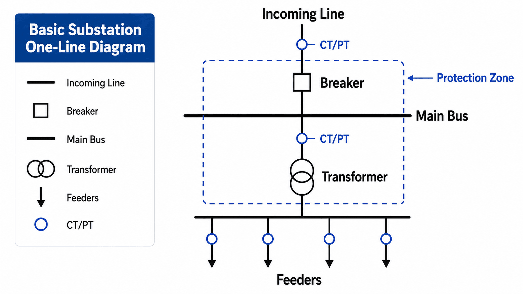
Incoming line, breaker, and main bus
The incoming line brings power into the substation from a transmission, subtransmission, generator, or collector circuit. The breaker provides interrupting capability, while the main bus creates a shared electrical node that can connect multiple circuits through a controlled arrangement.
Transformer and feeders
The transformer changes voltage between system levels. Downstream feeders then carry power to distribution circuits, plant loads, or other parts of the system. In a distribution substation, each feeder is usually protected so a fault on one circuit does not unnecessarily trip the entire station.
CT/PT points and protection zones
CTs and PTs or VTs feed measurement signals to relays, meters, and control systems. The protection zone shown on a one-line diagram helps engineers understand which breaker should operate for a specific fault and what equipment is protected by a relay scheme.
How Substations Detect and Clear Faults
Protection is one of the most important reasons substations exist. A fault may be caused by insulation failure, lightning, animals, equipment failure, conductor contact, contamination, or damaged cables. The substation protection system must detect the abnormal condition, select the right breaker, and isolate the faulted section without unnecessarily disconnecting healthy equipment.
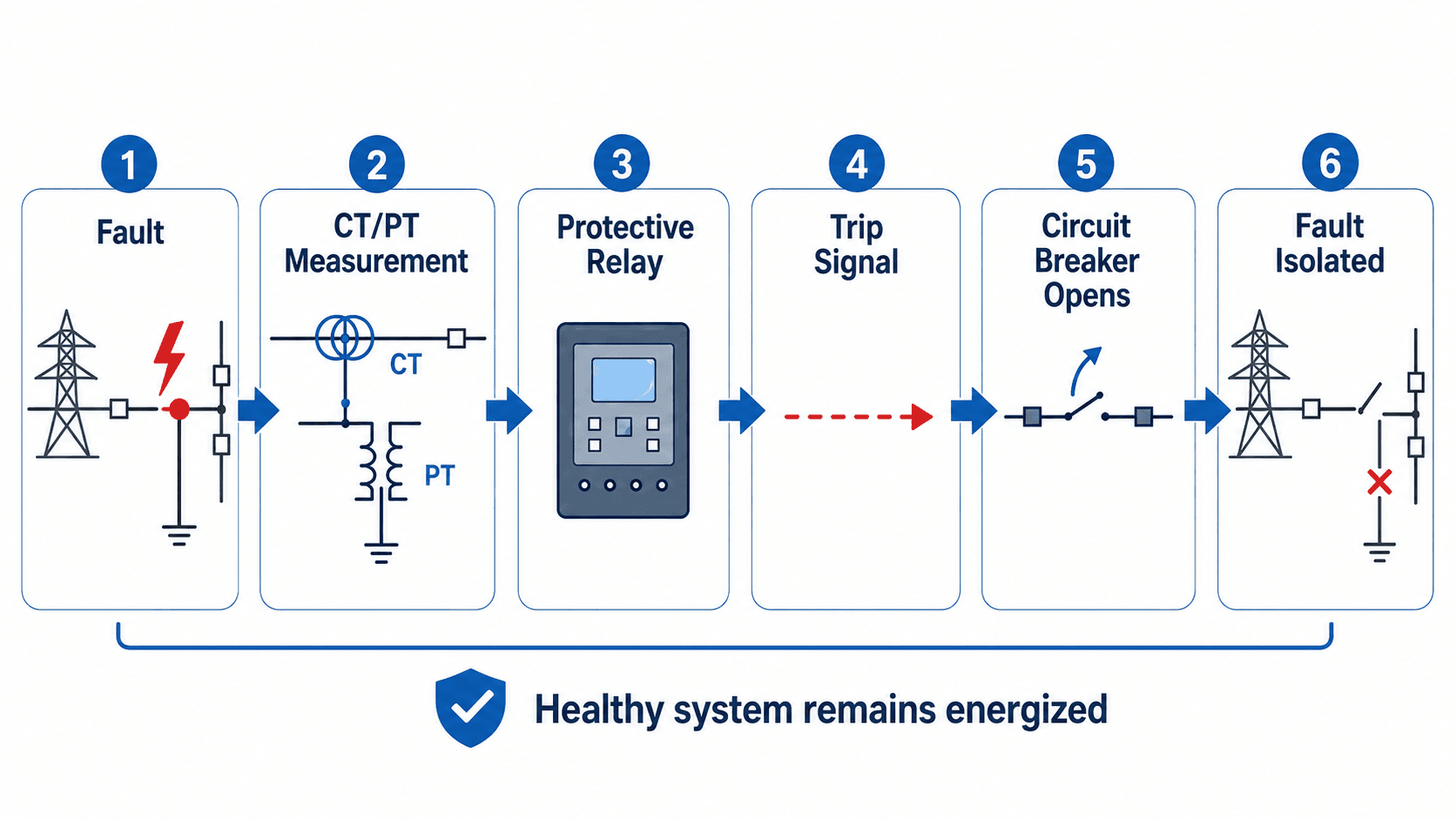
Measurement comes first
CTs and PTs/VTs convert primary system quantities into lower-level signals that relays can evaluate. Current magnitude, voltage level, phase angle, frequency, direction, and differential comparison can all be used depending on the protection scheme.
The relay decides what should trip
Protective relays compare measured signals against settings and logic. For feeder faults, overcurrent protection or directional elements may operate. For transformer faults, differential protection may compare current entering and leaving the protected zone. For bus faults, bus differential protection may trip several breakers very quickly.
The breaker isolates the fault
Once the relay issues a trip command, the breaker opens to interrupt current. The goal is selective isolation: trip the smallest practical part of the system while protecting equipment and maintaining service to the rest of the grid.
AIS, GIS, and Bus Arrangement Tradeoffs
Substation layout is not only an equipment placement problem. It affects cost, footprint, reliability, outage exposure, maintenance access, safety clearances, future expansion, and protection complexity. Two major layout decisions are the insulation system and the bus arrangement.
| Design choice | Where it fits | Engineering tradeoff |
|---|---|---|
| Air-insulated substation (AIS) | Outdoor sites with enough land and conventional utility layouts. | Usually easier to visually inspect and maintain, but requires larger clearances and more physical space. |
| Gas-insulated substation (GIS) | Urban, indoor, coastal, industrial, or space-constrained sites. | Compact and protected from weather, but typically higher cost, specialized maintenance, gas monitoring, and environmental management where SF6-insulated equipment is used. |
| Single bus | Simple distribution substations or lower-criticality applications. | Lower cost and simpler operation, but bus maintenance or bus failure can affect many circuits. |
| Main-and-transfer bus | Sites needing more maintenance flexibility without full duplication. | Improves outage management but adds switching steps and operational complexity. |
| Ring bus or breaker-and-a-half | Transmission substations where reliability and maintenance flexibility are critical. | Higher cost and protection complexity, but better ability to maintain service during equipment outages. |
The lowest-cost layout is not always the lowest-risk layout. A bus arrangement that saves equipment may create longer outages, more difficult switching, or greater exposure during maintenance.
Substation Field Review Checklist
A useful way to understand a substation is to review it by function. Instead of memorizing equipment names, ask what each part does for power flow, protection, safety, reliability, and operations.
Trace the incoming source, identify the bus arrangement, locate the transformer path, identify outgoing feeders, check the protection zones, confirm control power, and then review grounding, surge protection, access, drainage, and maintenance constraints.
| Review item | What to look for | Why it matters |
|---|---|---|
| Power path | Incoming line, breaker, bus, transformer, low-side bus, and outgoing feeders. | Confirms how power actually moves and what equipment is in series with the load. |
| Protection zones | CT/PT locations, relay functions, breaker trip paths, and zone boundaries. | Determines which fault is cleared by which breaker and whether healthy circuits remain energized. |
| Equipment ratings | Transformer MVA, breaker interrupting rating, bus ampacity, insulation class, and surge arrester rating. | Equipment must match load current, fault current, voltage level, and system transient conditions. |
| Grounding and bonding | Ground grid, equipment bonds, fence grounding, cable shields, and neutral grounding method. | Grounding controls touch potential, step potential, fault-current paths, and personnel safety. |
| Control power | Station batteries, chargers, DC panels, trip circuits, alarms, and relay power supply. | Breakers may fail to trip if the control power system is neglected or unavailable. |
| Maintenance access | Clearances, switching isolation points, equipment removal paths, crane access, and working space. | A design that is electrically correct can still be operationally difficult or unsafe to maintain. |
| Environmental controls | Drainage, oil containment, corrosion exposure, wildlife protection, vegetation, and security fencing. | Field conditions often drive long-term reliability more than the simplified one-line diagram suggests. |
Engineering Judgment and Field Reality
Textbook substation diagrams are clean, but real substations operate in weather, dust, salt, heat, ice, wildlife exposure, vegetation pressure, aging equipment, limited outage windows, and human switching constraints. Engineers must consider how equipment will be inspected, isolated, tested, replaced, and operated during abnormal system conditions.
Transformer condition, oil containment, breaker mechanism health, relay testing, battery capacity, SCADA communications, grounding integrity, infrared hot spots, cable terminations, and corrosion can all become reliability issues. A substation may look normal from outside the fence while still having hidden operational risk in control wiring, protection settings, or aging insulation.
Losses, voltage control, and loading also matter. A substation is not only a protection point; it is part of the larger system that affects power delivery efficiency, voltage profile, thermal loading, and reliability. For more context, see the Turn2Engineering guide on power system efficiency.
The one-line diagram tells you how the system should operate electrically. It does not show whether a disconnect can be safely reached, whether a breaker mechanism is slow, whether a battery string is weak, or whether a cable termination is heating under load.
Common Substation Failure Modes
Substation reliability depends on many systems working together. A failure may start in primary equipment, secondary wiring, protection settings, control power, insulation, grounding, communications, or environmental exposure.
| Failure mode | What may happen | Practical check |
|---|---|---|
| Transformer overheating or oil issues | Winding insulation may age faster, alarms may occur, or the transformer may trip on protection. | Review loading, cooling system operation, oil condition, dissolved gas trends, and thermal inspection results. |
| Breaker failure to trip or close | A fault may remain energized longer than expected or service restoration may be delayed. | Check mechanism timing, trip coils, close coils, control voltage, breaker maintenance records, and breaker failure protection. |
| Relay misoperation | The wrong breaker may trip, a healthy circuit may be disconnected, or a real fault may not clear correctly. | Review relay settings, CT/PT polarity, logic, coordination, event records, and commissioning test results. |
| CT saturation or wiring error | Relay measurements may be distorted during faults, especially for differential or high-current events. | Check CT ratios, burden, polarity, grounding, wiring diagrams, and fault-current assumptions. |
| Station battery or charger failure | Relays may remain powered but breaker trip or close circuits may not operate when needed. | Test battery capacity, charger alarms, DC panel status, trip circuit monitoring, and maintenance logs. |
| Surge arrester or insulation failure | Lightning or switching transients may damage transformer bushings, cable terminations, or other insulation systems. | Review arrester condition, insulation coordination, line entrance equipment, and surge exposure. |
| Wildlife, vegetation, or contamination fault | Animals, nests, debris, dust, salt, or vegetation may create flashover paths or mechanical interference. | Inspect fencing, covers, barriers, clearances, wash practices, vegetation management, and contamination patterns. |
| SCADA or communications loss | Operators may lose remote indication, control, alarms, or event visibility. | Check communications health, time synchronization, alarm points, remote terminal units, and local operating procedures. |
When Simplified Substation Explanations Break Down
A simplified explanation of substations breaks down when the reader assumes every substation has the same equipment, the same purpose, or the same level of redundancy. Substations are designed around their voltage level, available fault current, ownership, reliability target, protection philosophy, available space, and operating practices.
- A switching station may not step voltage up or down, even though many beginner explanations describe substations mainly as transformer sites.
- A distribution substation may have feeder protection priorities that are different from a transmission substation with bus differential, line distance, or breaker failure schemes.
- A compact GIS installation may look very different from an outdoor AIS yard, even though the one-line diagram may represent similar electrical functions.
- A renewable collector substation may focus heavily on medium-voltage collection, step-up transformation, metering, interconnection protection, and utility compliance.
- A physically simple substation can still have complex relay coordination, communications, grounding, and control power requirements.
Common Substation Mistakes and Misconceptions
Many misunderstandings come from treating a substation as a single piece of equipment rather than a system. The transformer is highly visible, but the less visible protection, control, grounding, and switching logic often determine how safely and reliably the site performs.
- Assuming substations generate electricity: Most substations route, transform, switch, protect, and control power generated elsewhere.
- Confusing disconnect switches with circuit breakers: Disconnects provide isolation, while breakers are designed to interrupt load and fault current.
- Ignoring the DC control system: Relays and breaker trip circuits may depend on station batteries and chargers during abnormal events.
- Reading the one-line as the physical layout: One-line diagrams show electrical relationships, not actual equipment spacing, orientation, or access routes.
- Overlooking grounding: Ground grids, bonding, neutral grounding, and surge protection are central to safe substation performance.
The biggest beginner mistake is thinking a substation is “just a transformer.” A substation is a coordinated system of equipment, protection, control, grounding, and operating procedures.
Useful References and Design Context
Substation design and operation involve utility standards, safety procedures, owner requirements, protection studies, grounding studies, equipment standards, and site-specific engineering decisions. For a deeper engineering-oriented public reference, the USDA Rural Utilities Service design guide is a useful technical source for rural substation design context.
- USDA Rural Utilities Service: USDA design guide for rural substations provides public technical guidance on substation design topics such as site considerations, major equipment, grounding, protection, structures, and station layout.
- Project-specific criteria: Utility interconnection requirements, owner standards, protection coordination studies, grounding studies, equipment specifications, and local safety requirements often control final substation decisions.
- Engineering use: Engineers use references and standards to confirm terminology, safety expectations, insulation requirements, equipment duties, protection zones, operating procedures, and maintenance requirements.
Frequently Asked Questions
A substation is a high-voltage power system facility that connects parts of the grid and usually performs some combination of voltage transformation, switching, protection, metering, control, and power routing.
Most substations do not generate electricity. They move, transform, switch, protect, and control power that comes from generators, transmission lines, distribution feeders, renewable plants, or industrial electrical systems.
Common substation equipment includes power transformers, circuit breakers, disconnect switches, busbars, protective relays, CTs, PTs or VTs, surge arresters, grounding systems, control buildings, batteries, SCADA equipment, and sometimes capacitor banks or reactors.
A transmission substation connects high-voltage transmission circuits and may step voltage up, step voltage down, or switch bulk power. A distribution substation typically steps voltage down to a medium-voltage level and feeds local distribution circuits.
A transformer is a piece of equipment that changes voltage. A substation is the larger facility or electrical node that may include transformers, breakers, switches, relays, busbars, grounding, controls, metering, and communication systems.
Substations contain exposed or enclosed high-voltage equipment, high fault-current energy, energized conductors, grounding hazards, arc-flash risk, and switching equipment. Access is restricted because safe work requires training, procedures, clearances, and protective equipment.
Summary and Next Steps
Substations are the controlled nodes of the power system. They transform voltage, switch circuits, protect equipment, measure electrical quantities, support remote control, and route power between transmission, distribution, generation, renewable, and industrial systems.
The most useful way to understand a substation is to follow the power path and then check the protection path. Identify the incoming source, breaker, bus, transformer, feeders, CT/PT measurement points, relays, grounding, control power, maintenance access, and likely failure modes before assuming how the site operates.
Where to go next
Continue your learning path with related Turn2Engineering resources.
-
Switchgear
Learn how breakers, switches, and protective equipment are packaged and applied in power systems.
-
Protective Relays
Understand the devices that decide when a breaker should trip during abnormal electrical conditions.
-
Voltage Regulation
Explore how power systems maintain acceptable voltage levels using transformers, controls, and reactive power equipment.