Key Takeaways
- Definition: Earth retaining structures are engineered systems that hold back soil or rock while controlling lateral movement, groundwater effects, and stability.
- Use case: They are used when a project needs to create or maintain a grade difference, support an excavation, protect infrastructure, or build within limited space.
- Main decision: Engineers must match the wall system to site geometry, ground conditions, drainage, construction staging, and movement tolerance—not just wall height.
- Outcome: After reading, you should understand the major retaining system types, the basic design workflow, the main checks, and where simplified approaches stop being reliable.
Table of Contents
Introduction
Direct answer: Earth retaining structures are geotechnical systems used to hold back soil or rock, create usable grade differences, and keep excavations or embankments stable. In practice, their design is controlled by earth pressure, groundwater, deformation limits, overall stability, constructability, and how sensitive nearby structures are to movement.
This page is for engineering students, FE or PE exam candidates, and practicing engineers who want a clearer framework for understanding how retaining systems are selected and checked. Instead of treating every wall as a simple textbook problem, the goal here is to explain how earth retaining structures behave in the field, what makes one system better than another, and where judgment matters as much as calculation.
The dominant search intent for this topic is a mix of definition, design application, comparison, and practice-oriented decision-making. That means a useful page should do more than define retaining walls. It should connect system selection, earth pressure behavior, drainage, movement, external stability, and construction reality into one practical workflow.
Earth Retaining Structures infographic
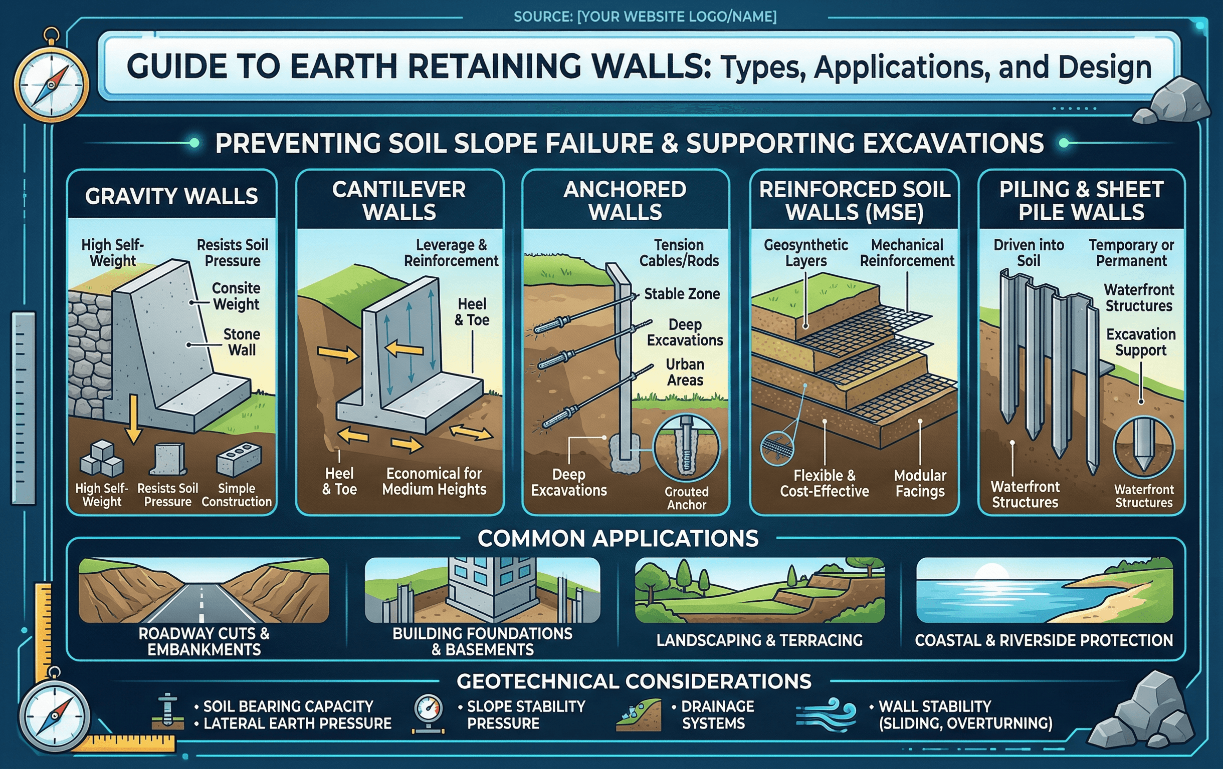
Readers should notice that successful retaining design is never only about the wall facing. The soil behind the wall, the water moving through it, the support below it, and the space available for construction all shape the right solution.
What are earth retaining structures?
Earth retaining structures are systems built to resist the lateral forces generated by soil, rock, surcharge loads, and often groundwater. They allow engineers to create vertical or near-vertical grade changes that would otherwise require a wide natural slope. That makes them essential in dense urban projects, transportation corridors, bridge approaches, waterfront works, utility infrastructure, and temporary excavations where space is limited.
The term is broader than earth retaining walls. It includes gravity walls, reinforced concrete cantilever walls, mechanically stabilized earth systems, sheet pile walls, soldier pile and lagging walls, anchored walls, braced excavation systems, soil nail walls, and hybrid systems. Some are intended for permanent service, while others are mainly temporary support-of-excavation systems.
The engineering mission is straightforward to say but harder to execute: resist lateral loads, keep movements within acceptable limits, drain water safely, and maintain adequate stability during construction and long-term service. A wall that is structurally strong can still perform poorly if the backfill is wrong, the drainage path clogs, or the foundation soils deform more than expected.
Before discussing wall details, ask the higher-level question first: is the project really controlled by wall capacity, or by available footprint, settlement tolerance, utility conflicts, groundwater, or staged construction?
Core principles, loads, and what controls performance
Retaining systems work because they develop resistance against lateral earth loading while transferring that loading into the ground through base reaction, passive resistance, anchors, internal reinforcement, bracing, or a combination of these mechanisms. To understand their behavior, engineers usually start with four core ideas: earth pressure state, groundwater, wall stiffness and movement, and foundation support.
Key variables and typical ranges
The most important project variables are not exotic. They are the wall height, backfill unit weight, friction angle, cohesion when appropriate, groundwater level, surcharge intensity, and movement tolerance of the site. Even small changes in these inputs can move a project from a simple cantilever wall to an anchored or reinforced soil solution.
- H Retained height, typically in ft or m; one of the fastest ways to narrow candidate systems.
- γ Unit weight of retained soil, usually pcf or kN/m³; controls lateral stress magnitude.
- φ Soil friction angle, in degrees; strongly affects active and passive earth pressure estimates.
- c Apparent or effective cohesion; use carefully because long-term drained conditions may reduce its benefit.
- q Uniform surcharge load from traffic, structures, stockpiles, or adjacent foundations.
- u Pore water pressure; often the forgotten load that turns a stable wall into a problem.
- δ Wall-soil interface friction angle; important for Coulomb-based calculations and sliding resistance.
A practical way to think about retaining behavior is this: soil wants to move laterally, the wall and supporting system resist that movement, and the amount of movement that actually occurs influences the pressure state. Flexible systems may mobilize active pressure more readily, while stiff systems with limited movement may stay closer to at-rest conditions. That is why wall type and serviceability criteria matter as much as strength.
When numbers look surprisingly low, check whether you have unconsciously assumed active pressure for a wall that will not move enough to develop it.
How engineers choose the right retaining system
Choosing a retaining system is usually a comparison problem, not a single-solution calculation. Engineers begin by defining the retained height, temporary versus permanent use, right-of-way limits, utilities, groundwater, and acceptable movement. From there, the field narrows quickly.
Start with geometry and performance requirements. If footprint is available and settlements are tolerable, gravity or mechanically stabilized earth systems may be efficient. If footprint is tight and height is moderate, reinforced concrete cantilever walls often become attractive. If excavation support is needed in constrained urban conditions, soldier pile, sheet pile, braced, or anchored systems may govern. If the face must be constructed from the top down with limited access, soil nails or specialized support systems may be preferred.
Wall selection is heavily shaped by constructability. A theoretically efficient system may be a poor choice if tiebacks extend into easements, if utilities prevent excavation, if groundwater makes open cuts risky, or if the contractor cannot reliably install the required reinforcement or drainage.
| System | Best fit | Main advantage | Main limitation |
|---|---|---|---|
| Gravity wall | Low to moderate heights with footprint | Simple behavior and robust construction | Needs space and good bearing support |
| Cantilever RC wall | Moderate permanent walls | Efficient structural use of concrete | Drainage and foundation support are critical |
| MSE wall | Transportation and embankment projects | Fast, flexible, and settlement tolerant | Needs reinforcement length and quality backfill |
| Sheet pile wall | Waterfronts and temporary support | Fast installation in suitable ground | May struggle in dense obstructions or hard strata |
| Soldier pile and lagging | Urban excavations | Adaptable around utilities and staged cuts | Movement control may be more demanding |
| Anchored or braced wall | Deep constrained excavations | Can support large cuts in tight sites | Complex staging and temporary load paths |
Equations and calculations engineers use first
The first-pass calculations for retaining design usually estimate lateral earth pressure, surcharge loading, and the resulting force location. For a simple level backfill case under active earth pressure assumptions, a common starting point is:
Here, \(K_a\) is the active earth pressure coefficient, \(\phi\) is the soil friction angle, \(\sigma_h\) is lateral stress at depth \(z\), \(\gamma\) is unit weight, and \(P_a\) is the resultant active force per unit wall length. For a uniform surcharge \(q\), the added lateral force is commonly estimated as \(K_a q H\) in simple screening calculations.
For many practical walls, engineers also check at-rest pressure, passive resistance in front of the toe where allowed, and hydrostatic loading. A core geotechnical idea behind all of this is effective stress:
Total stress alone does not tell the story. If pore pressure rises, effective stress drops, shear strength may reduce, and wall loads or deformations can increase. That is why drainage details often matter more to long-term performance than a small change in stem thickness.
Worked example: screening a permanent wall concept
Example
Consider a permanent wall retaining 12 ft of granular backfill with \(\gamma = 120\) pcf and \(\phi = 32^\circ\). Assume level backfill, no cohesion benefit, and a 250 psf traffic surcharge. A quick screening check begins by estimating \(K_a\). Using Rankine theory, \(K_a \approx 0.31\). The triangular soil force is then \(P_a = 0.5(0.31)(120)(12^2)\approx 2,678\) lb/ft. The uniform surcharge contributes \(P_q = (0.31)(250)(12)\approx 930\) lb/ft. The total first-pass lateral demand is about 3.6 kips/ft, before hydrostatic pressure, compaction-induced loads, seismic demand, or other project-specific effects are added.
That single number is not a final design. It is a screening value used to compare systems and identify what matters next. If the wall must sit close to a property line with little footprint, a conventional gravity wall may be ruled out. If nearby utilities or foundations are movement-sensitive, active pressure assumptions may be unconservative. If groundwater is present without dependable drainage, hydrostatic loading could become a dominant design case. The real value of the example is not just the arithmetic. It is the way the estimate quickly reveals which questions must be answered before committing to a wall type.
Engineering judgment and field reality
In practice, retaining systems rarely fail because someone forgot the basic triangular earth pressure diagram. Problems are more often driven by a mismatch between assumptions and field conditions. Backfill is different than specified. Drainage outlets clog. Excavation proceeds out of sequence. Groundwater appears seasonally after design. A wall face looks fine, but the reinforced zone or foundation soils are doing something different than the drawings assumed.
Field reality also changes how engineers think about soil properties. The friction angle used in design is not just a lab number. It reflects material quality, placement, compaction, drainage condition, and construction control. Similarly, cohesion in fine-grained soils may appear helpful in the short term, but permanent design is often governed by drained or softened conditions that justify a much more conservative view.
Water management and earthwork quality routinely decide retaining performance. Many wall distress cases begin with poor backfill, inadequate compaction control, missing drainage aggregate, clogged outlets, or groundwater assumptions that were never validated during construction.
Experienced engineers also watch the construction sequence closely. A wall may be acceptable in final condition but vulnerable during interim stages. Temporary cuts, staged surcharges, unbalanced fills, or delayed tieback installation can all create load paths that do not exist in the final drawings. For deep excavations, the temporary condition may be the most demanding condition.
When this breaks down
Simplified retaining design begins to break down when the problem is no longer close to the assumptions behind the equations. Irregular backfill geometry, layered soil profiles, sloping ground, nearby foundation loads, surcharges that are not uniform, and time-dependent groundwater conditions all complicate the load picture. The same is true when the wall is stiff enough that at-rest pressure is more realistic than active pressure, or when seismic demand changes both load magnitude and deformation expectations.
The method also breaks down when the retaining problem is really a global stability problem. A wall can pass sliding and overturning checks yet still sit within a larger unstable mass. This is common where weak layers, soft foundation soils, or deep-seated failure surfaces control. In these cases, the engineer has to step back and ask whether the wall is the system of interest, or merely one component inside a broader slope or embankment problem. Pages like Slope Stability, Soil Mechanics, and Geotechnical Earthworks become part of the same workflow.
More detailed analysis is usually warranted when deformations are tightly limited, when staged excavation matters, when groundwater flow interacts with the wall, or when construction affects adjacent structures. At that point, soil-structure interaction, seepage analysis, reinforcement load checks, or observational methods may matter more than a single closed-form pressure equation.
Common pitfalls and engineering checks
- Using active earth pressure for a wall that is too stiff or too constrained to move enough.
- Ignoring hydrostatic pressure or assuming drainage will work without a maintainable path.
- Checking only wall stability and forgetting global stability or foundation settlement.
- Relying on passive resistance that may be excavated later or not be dependable in service.
- Using laboratory strength values without asking whether construction quality will actually reproduce them in the field.
- Skipping temporary-stage checks for braced, anchored, or top-down systems.
One of the costliest mistakes is treating groundwater as a side note. In retaining work, water changes pressure, strength, construction difficulty, long-term maintenance, and the consequence of poor drainage all at once.
| Check | Why it matters | Typical question to ask | Common miss |
|---|---|---|---|
| Sliding | Confirms lateral resistance at the base or support system | Is friction, keying, anchoring, or passive resistance adequate? | Over-crediting passive resistance |
| Overturning | Checks rotational stability about the toe or support line | Does the resultant stay within acceptable limits? | Ignoring surcharge or water |
| Bearing | Prevents excessive base pressure or foundation failure | Can the supporting soil safely carry the wall reactions? | Skipping settlement sensitivity |
| Global stability | Captures deep-seated failure mechanisms | Is the wall inside a larger unstable soil mass? | Focusing only on wall section checks |
| Deformation | Protects nearby structures and serviceability | How much movement is acceptable for the site? | Assuming strength controls everything |
| Drainage | Controls pore pressure and long-term performance | Will water be collected, routed, and maintained? | No durable drainage path |
Visualizing the retaining problem before you size the wall
A useful mental sketch for earth retaining structures is a section cut showing the retained soil wedge, the drainage layer, groundwater line, surcharge location, and the load transfer path from the wall into the ground. That simple sketch often reveals the real project question faster than a spreadsheet does. Is this mostly a wall problem, a seepage problem, a staged excavation problem, or a global stability problem?
Another helpful visualization is to compare three separate envelopes: the zone the wall occupies, the zone the retained soil wants to move through, and the zone construction equipment needs to access. Many bad wall choices happen because the final geometry is drawn well but the temporary excavation and installation space are not.
Relevant standards and design references
Specific project requirements depend on jurisdiction and owner criteria, but these references commonly shape retaining design decisions and checks:
- AASHTO LRFD Bridge Design Specifications: Commonly used for transportation-related retaining structures, especially where walls interact with bridge approaches, traffic surcharge, and agency design criteria.
- FHWA retaining wall and MSE guidance: Widely used for wall selection, reinforced soil concepts, drainage detailing, external and internal stability, and transportation wall practice.
- USACE engineering manuals: Valuable for earth pressure, seepage, excavation support, and geotechnical design methodology on projects with demanding groundwater or staged construction issues.
- Project geotechnical report and local DOT manuals: These are often the real source of truth for allowable parameters, drainage assumptions, seismic criteria, and construction-specific requirements on a given site.
Frequently asked questions
Retaining walls are one part of the broader earth retaining structures category. The broader term includes permanent walls, temporary support-of-excavation systems, anchored and braced systems, sheet piles, reinforced soil systems, and other arrangements used to control soil movement and grade differences.
The controlling factor is often movement, groundwater, footprint, or global stability rather than the wall section alone. The best system is the one that satisfies strength, deformation, drainage, constructability, and project constraints together.
Active pressure assumptions can become unsafe when the wall is too stiff or too restrained to move enough to mobilize the active condition. That is especially important for basement walls, braced systems, and sites where adjacent infrastructure limits allowable movement.
Drainage controls pore pressure, and pore pressure directly affects effective stress, shear strength, wall loads, and long-term performance. A well-sized wall can still distress badly if the drainage path behind it is not built, protected, and maintained.
They are used in bridge approaches, highways, rail corridors, basements, utility excavations, waterfront edges, grade separations, embankments, and any project where safe grade change must be created without using a wide natural slope.
Summary and next steps
Earth retaining structures are not just walls. They are geotechnical systems that have to manage soil, water, deformation, support conditions, and construction sequence together. A sound design begins with a realistic ground model and a clear understanding of what the project can tolerate in terms of footprint, movement, and long-term maintenance.
In many projects, the most important decision is system selection rather than detailed sizing. Once the wrong system is chosen, later calculations rarely fix the mismatch. That is why experienced engineers focus early on groundwater, movement criteria, foundation support, and how the wall will actually be built. The best retaining solution is usually the simplest system that still satisfies strength, serviceability, constructability, and risk.
From here, the most valuable next step is usually to deepen one of the core subtopics that truly controls design on your project: earth pressure behavior, global stability, backfill and drainage performance, or a specific wall type such as reinforced concrete or reinforced soil systems.
Where to go next
Continue your learning path with these curated next steps.
-
Read a deeper dive on Retaining Wall Design
Best for moving from broad system understanding into more detailed earth pressure, drainage, and stability workflow.
-
Study Slope Stability
Useful when the retaining problem is part of a larger mass movement or embankment stability problem.
-
Practice with a related Turn2Engineering retaining wall calculator
Apply the concepts with numbers and connect theory to first-pass design checks.