
Key Takeaways
- Core idea: A stand-alone power system supplies electricity without a utility grid connection, so local generation, storage, controls, and loads must operate as one coordinated system.
- Engineering use: These systems are used where grid extension is unavailable, unreliable, too expensive, or impractical, such as remote homes, telecom sites, farms, research stations, and isolated facilities.
- What controls it: The design is controlled by the load profile, peak demand, surge loads, battery autonomy, generation resource, inverter rating, backup strategy, and protection scheme.
- Practical check: A reliable system is sized from the loads first, not from the solar array or generator first.
Table of Contents
Introduction
Stand-alone power systems are independent electrical systems that generate, store, and deliver power without a connection to the utility grid. A complete system usually includes local generation, battery storage, power conversion, controls, protection, and a backup strategy so critical loads can operate when renewable output changes.
How Stand-Alone Power Systems Deliver Off-Grid Power
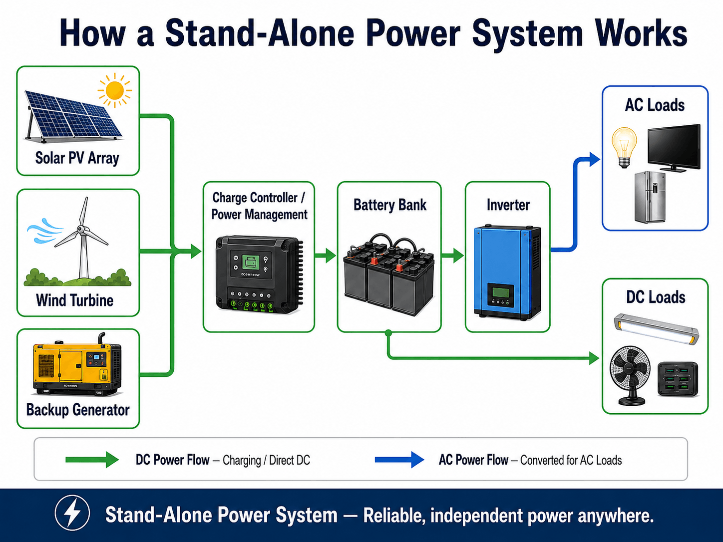
Notice that generation, storage, and conversion are separate functions. Solar panels or generators do not make a system reliable by themselves; reliability comes from matching the complete system to the load profile.
What is a Stand-Alone Power System?
A stand-alone power system, often abbreviated SAPS, is an off-grid electrical system that serves a load without relying on a central utility grid. It may use solar photovoltaic panels, wind turbines, micro-hydro, engine-driven generators, battery storage, inverters, charge controllers, switchgear, and monitoring equipment.
The key engineering difference is responsibility. In a grid-connected building, the utility grid absorbs many power balance and reliability problems. In a stand-alone system, the local equipment must provide energy, maintain voltage and frequency, handle load changes, protect equipment, and recover from low-generation periods.
Stand-alone power design is not just “add solar panels and a battery.” It is a load-serving problem where energy production, usable storage, inverter capacity, backup generation, protection, and load management must be designed together.
Stand-Alone Power System Components
A stand-alone power system is a group of coordinated subsystems. Each component has a different job, and reliability depends on how well those jobs are matched to the site load profile. For a broader foundation, review power system components.
| Component | Role in the system | Engineering implication |
|---|---|---|
| Solar PV array, wind turbine, micro-hydro, or generator | Produces electrical energy locally instead of importing it from the grid. | The available resource, seasonal variation, fuel access, and maintenance burden control long-term reliability. |
| Battery bank | Stores energy for use when generation is lower than load demand. | Usable capacity depends on depth of discharge, temperature, efficiency, aging, and reserve requirements. |
| Charge controller or power management system | Controls battery charging and coordinates energy sources with storage. | Poor control can shorten battery life, cause nuisance generator starts, or leave usable energy stranded. |
| Inverter | Converts DC battery power into AC power for standard loads. | It must handle continuous load, surge load, motor starting, waveform quality, and overload duration. |
| Protection and disconnects | Isolate equipment and protect conductors, batteries, and loads from faults. | Fault current behavior can be different from utility-fed systems, so protection coordination matters. |
| Monitoring and controls | Track state of charge, generator operation, alarms, and energy production. | Without monitoring, a system may appear fine until the battery is deeply discharged or the generator fails to start. |
Stand-Alone Power System Design Steps
The design should begin with the load, not the equipment catalog. Solar panels, batteries, and generators are selected only after the engineer understands the energy demand, peak demand, operating schedule, critical loads, and acceptable risk of outage.
Daily energy, \(E_{\text{daily}}\), is the sum of each load power \(P_i\) multiplied by its operating time \(t_i\). In practice, engineers also account for seasonal use, standby consumption, inverter losses, battery efficiency, growth allowance, and loads that may start at the same time.
- kWh/day Daily energy use. This drives battery storage and generation requirements.
- kW Peak demand. This drives inverter, generator, and protection sizing.
- Surge Short-duration starting load from motors, pumps, compressors, tools, and appliances.
- Autonomy How long the site must operate with low or no renewable input before backup is needed.
Step 1: Build the load profile
List each load, power rating, operating hours, duty cycle, starting current, and whether it is critical. A remote telecom cabinet and a small cabin may have similar daily energy use but very different reliability requirements.
Step 2: Size storage from usable energy, not nameplate capacity
A battery labeled with a nominal capacity does not provide that entire value for normal operation. Usable energy is reduced by depth-of-discharge limits, temperature, aging, conversion losses, reserve margin, and battery management constraints.
Step 3: Match generation and backup to the worst practical period
The array or turbine should not be sized only for an average day. Engineers check seasonal resource conditions, low-generation periods, recharge time, generator fuel logistics, and whether noncritical loads can be delayed or shed.
| Design input | What to collect | Why it controls the system |
|---|---|---|
| Daily energy use | kWh/day by load, season, operating schedule, and duty cycle. | Sets the minimum storage and generation requirement. |
| Peak load | Maximum simultaneous kW expected during normal operation. | Controls inverter, generator, conductors, and protective device selection. |
| Surge load | Starting current from pumps, compressors, motors, tools, and appliances. | Prevents nuisance trips and inverter overload during equipment startup. |
| Required autonomy | Hours or days the site must run without adequate renewable generation. | Controls usable battery capacity and backup strategy. |
| Generation resource | Seasonal solar availability, wind resource, hydro flow, shading, and generator fuel access. | Determines whether the system can recover after poor-generation periods. |
| Critical load list | Loads that must remain powered during low-energy conditions. | Supports load shedding, priority circuits, and reserve planning. |
| Site access | Maintenance access, fuel delivery, weather exposure, and communication availability. | Changes the required monitoring, redundancy, and maintenance strategy. |
AC-Coupled vs DC-Coupled Stand-Alone Systems
Stand-alone systems may be arranged around a DC bus, an AC bus, or a hybrid of both. The architecture affects efficiency, expandability, generator integration, protection, control logic, and how easily new sources or loads can be added later.
| Architecture | How it works | Best fit | Design tradeoff |
|---|---|---|---|
| DC-coupled | PV or other DC sources charge the battery through a charge controller, and an inverter supplies AC loads. | Smaller off-grid systems, battery-focused designs, and systems with simple renewable charging paths. | Often efficient for charging but may be less flexible when expanding AC generation or larger distributed loads. |
| AC-coupled | Generation sources, battery inverter, and sometimes generator output interact through an AC bus. | Larger systems, retrofit projects, expandable sites, or installations with multiple AC sources. | Can improve flexibility, but controls, synchronization, and fault behavior need careful review. |
| Hybrid AC/DC | Some loads and sources remain on DC while major building loads are served from AC. | Sites with telecom loads, controls, lighting, DC equipment, and standard building circuits. | Can reduce some conversion losses, but protection and documentation must be clear. |
The AC/DC decision is closely related to AC vs DC power systems. A clean diagram may show simple arrows, but the final architecture should be reviewed for efficiency, maintainability, fault isolation, and future expansion.
Battery Sizing and Autonomy in Stand-Alone Systems
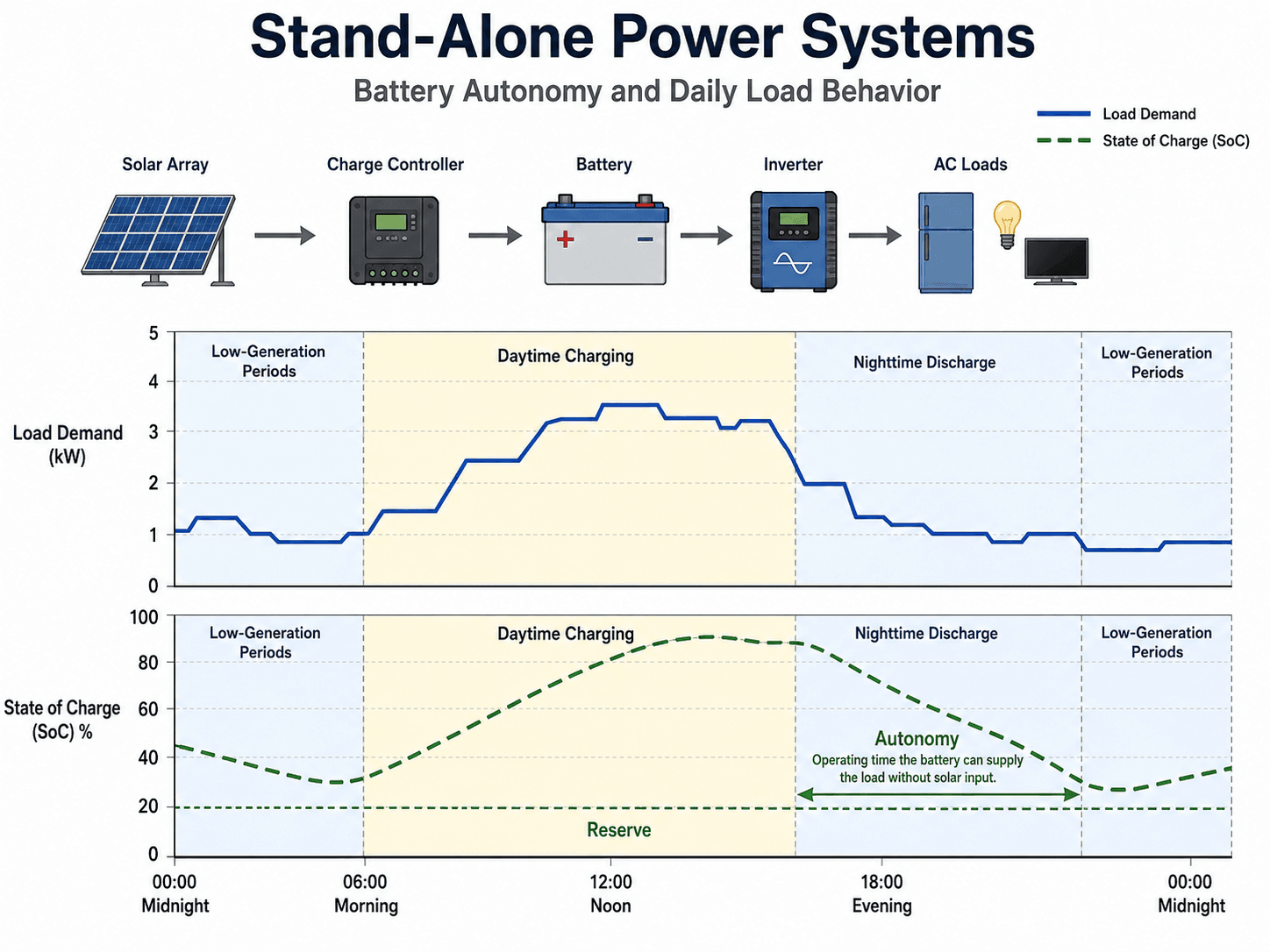
Battery autonomy is the amount of time a stand-alone system can serve loads from stored energy when generation is unavailable or inadequate. It is one of the most important reliability decisions because it affects cost, battery size, generator runtime, and outage risk.
Usable stored energy is lower than nominal battery energy. \(DOD_{\text{allowable}}\) represents the allowable depth of discharge, and \(\eta\) represents efficiency losses. The actual value also depends on battery chemistry, battery management settings, temperature, cycle life expectations, and aging.
Example: sizing storage for a small remote load
Assume a small remote site uses 8 kWh/day and needs 2 days of battery autonomy. If the allowable depth of discharge is 80% and the overall storage efficiency is 90%, the nominal battery energy can be estimated as:
This does not mean the final battery must be exactly 22.2 kWh. A real design may need additional allowance for cold temperature, battery aging, inverter losses, generator recharge limits, future load growth, and the owner’s tolerance for outage risk.
A system that works during a sunny commissioning week may still fail during a cloudy winter period, after battery aging, or when new loads are added. Autonomy should be checked against realistic low-generation periods, not just average production.
Stand-Alone vs Grid-Tied Solar vs Microgrid
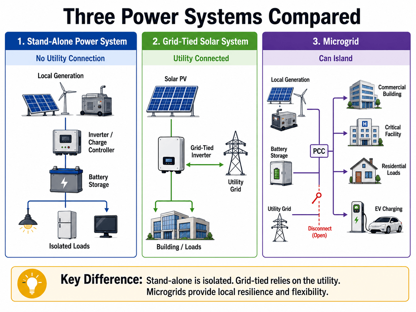
Stand-alone power systems are often confused with grid-tied solar systems and microgrids. The difference is not simply the presence of solar panels. The key question is whether the system can rely on the utility grid, whether it can island, and how many loads and sources are coordinated.
| System type | Utility connection | Storage requirement | Best fit |
|---|---|---|---|
| Stand-alone power system | No normal utility connection. | Usually required for reliable operation. | Remote or isolated loads where the site must operate independently. |
| Grid-tied solar system | Connected to the utility grid. | Optional, depending on backup and self-consumption goals. | Buildings that want solar energy savings while still relying on the grid. |
| Microgrid | May connect to the utility and may island when needed. | Common, especially for resilience and control. | Campuses, critical facilities, communities, industrial sites, and resilience projects. |
Which system fits which situation?
| Situation | Better fit | Reason |
|---|---|---|
| No grid service nearby | Stand-alone power system | The site must generate, store, and control its own power independently. |
| Grid service exists and energy savings are the goal | Grid-tied solar system | The utility grid supports reliability while solar offsets energy use. |
| Critical facility wants resilience | Microgrid | Multiple sources, storage, controls, and islanding can support continuity during grid events. |
| Seasonal remote site | Stand-alone or hybrid system | The best option depends on seasonal loads, access, fuel logistics, and renewable resource availability. |
| Campus or industrial park | Microgrid | Multiple loads and coordinated control points often justify a microgrid architecture. |
For a deeper look at neighboring system types, compare this topic with microgrids and hybrid power systems.
Senior Engineer Review Checklist for Stand-Alone Systems
A stand-alone system review should test whether the design can serve the loads under realistic operating conditions. The checklist below focuses on the decisions most likely to affect reliability, maintainability, and field performance.
Start with the load profile, separate critical and noncritical loads, check peak and surge demand, select autonomy, confirm usable battery capacity, verify generation recovery, review backup operation, then check conductors, voltage drop, protection, monitoring, and maintenance access.
| Review check | What to look for | Why it matters |
|---|---|---|
| Load profile | Daily kWh, hourly pattern, seasonal operation, standby loads, and future additions. | Storage and generation cannot be trusted if the demand model is incomplete. |
| Peak and surge demand | Motors, pumps, compressors, refrigerators, power tools, and simultaneous starts. | The inverter or generator may trip even when daily energy capacity looks adequate. |
| Battery autonomy | Required hours or days of operation during poor renewable input. | Autonomy sets the practical reliability target and strongly affects cost. |
| Usable battery capacity | Depth of discharge, temperature correction, aging, efficiency, and minimum reserve. | Nameplate battery capacity can overstate the energy available to loads. |
| Generation recovery | Array size, wind resource, hydro availability, generator recharge rate, and seasonal worst cases. | The system must recover after low-generation periods, not just survive one discharge event. |
| Voltage drop and conductor length | Long DC runs, long AC feeders, low-voltage circuits, and high-current battery cables. | Voltage drop can reduce equipment performance and increase losses in remote installations. |
| Protection and isolation | Disconnects, fuses, breakers, grounding, bonding, and equipment ratings. | Stand-alone systems still need safe fault isolation and serviceable equipment boundaries. |
| Monitoring and maintenance | State of charge, generator start history, alarms, battery temperature, and service access. | Remote systems can degrade quietly unless operators can see problems early. |
Engineering Judgment and Field Reality
The hardest part of stand-alone power design is not drawing the block diagram. It is deciding which assumptions are realistic. Loads change, batteries age, winter production drops, fuel deliveries are missed, filters clog, conductors run longer than expected, and users often add equipment after commissioning.
The most reliable stand-alone systems are usually conservative about load growth, battery reserve, generator integration, monitoring, and maintenance access. The lowest first-cost design is often not the lowest-risk design.
For remote sites, maintainability can be as important as efficiency. A slightly less efficient system with better monitoring, easier access, simpler controls, and a proven backup sequence may outperform a highly optimized system that is difficult to troubleshoot in the field. System losses and conversion choices should also be reviewed through the lens of power system efficiency.
Maintenance reality for remote stand-alone systems
| Maintenance item | What to check | Why it matters |
|---|---|---|
| Battery condition | State-of-charge trends, temperature, alarms, terminal condition, and capacity decline. | Battery degradation is one of the fastest ways for autonomy assumptions to fail. |
| Generator readiness | Fuel, oil, filters, start sequence, charger output, alarms, and load test results. | Backup power only helps if the generator starts and carries the required load when needed. |
| PV array and renewable source | Soiling, shading, connectors, mounting, damage, wind exposure, and seasonal obstruction. | Reduced production increases battery cycling and backup generator runtime. |
| Inverter and controller logs | Overloads, temperature events, fault codes, firmware status, and generator start history. | Logs reveal recurring stress before it becomes a full outage. |
| Conductors and enclosures | Corrosion, looseness, water ingress, heat, conduit damage, and animal intrusion. | Remote installations often face harsher environmental conditions than indoor utility-fed equipment. |
| Load growth | New appliances, pumps, tools, heaters, network devices, and standby loads. | Small added loads can reduce autonomy and make a previously adequate system unreliable. |
When This Breaks Down
A simplified stand-alone power diagram breaks down when it hides timing, control, and reliability constraints. Real systems are dynamic: generation changes minute by minute, load demand is irregular, batteries have operating limits, and power electronics respond differently to faults than utility sources.
| Failure mode | What causes it | Practical check |
|---|---|---|
| Battery reaches reserve too often | Load growth, low solar production, battery aging, or unrealistic autonomy assumptions. | Compare actual state-of-charge history against the original load model. |
| Inverter trips during startup | Motor, pump, compressor, or tool surge current exceeds inverter overload capability. | Check surge ratings, starting sequence, and whether soft-start equipment is needed. |
| Generator fails to recover the system | Undersized charger, fuel issue, failed automatic start, or poor maintenance. | Perform periodic generator start and recharge tests under realistic load. |
| Voltage-sensitive loads malfunction | Long conductor runs, high current, inverter limits, or voltage drop in low-voltage circuits. | Review feeder lengths, conductor sizes, voltage drop, and load location. |
| Protection does not behave as expected | Fault current from inverters or batteries differs from utility-fed assumptions. | Review available fault current, breaker/fuse ratings, grounding, and disconnect locations. |
Long conductor runs and low-voltage circuits deserve special attention. If the installation includes long feeders, remote DC equipment, or high-current battery cables, the related concepts in low voltage power systems become especially important.
Common Mistakes and Practical Checks
Many stand-alone power issues come from incomplete assumptions rather than defective equipment. The checks below help separate a robust design from a system that only works under ideal conditions.
- Sizing from panel count instead of load demand: The energy source should be selected after daily energy, peak load, autonomy, and backup needs are understood.
- Ignoring small continuous loads: Routers, controls, sensors, standby electronics, and battery management equipment can dominate remote-site energy use.
- Underestimating cable losses: Low-voltage systems can carry high current, making conductor length and voltage drop especially important.
- Assuming the generator is only emergency equipment: In many remote systems, the generator is part of the energy management strategy and must be sized and maintained accordingly.
- Leaving out load management: Shedding noncritical loads can be more cost-effective than oversizing every component for rare events.
The biggest mistake is treating a stand-alone system like a small grid-tied solar installation. Without the grid, the battery, inverter, controls, generator, and protection scheme carry the full responsibility for continuity of service.
Related checks often include voltage drop, conductor sizing, connected load review, and power quality evaluation for sensitive equipment.
Engineering References and Design Guidance
Stand-alone power systems should be designed with attention to local electrical codes, equipment instructions, battery safety, grounding, disconnects, overcurrent protection, and project-specific reliability requirements. A useful U.S. public reference for understanding stand-alone renewable energy systems is the U.S. Department of Energy’s Energy Saver guidance.
- U.S. Department of Energy: DOE guidance on grid-connected and stand-alone renewable energy systems explains how stand-alone renewable systems can combine energy sources, storage, and efficiency improvements to improve reliability.
- Project-specific criteria: Final design decisions may also depend on the authority having jurisdiction, owner reliability targets, battery manufacturer limits, generator requirements, site access, and environmental conditions.
- Engineering use: References help frame the design review, but the final system still needs load analysis, protection review, commissioning checks, and a maintenance plan.
Frequently Asked Questions
A stand-alone power system is an electrical system that supplies loads without relying on the utility grid. It normally combines local generation, battery storage, power conversion, controls, and protection so the site can generate, store, and deliver its own electricity.
The main components are the energy source, battery bank, charge controller or power management system, inverter, protection equipment, monitoring, and the connected AC or DC loads. Many reliable systems also include a backup generator for extended low-generation periods.
A stand-alone system has no utility connection, so it must balance generation, storage, and load on its own. A grid-tied solar system remains connected to the utility, can import or export power, and typically does not need to carry the full reliability burden by itself.
Most practical stand-alone power systems need batteries or another energy storage method because generation and demand rarely occur at the same time. Without storage, loads would only operate when the generator source is producing enough power at that moment.
The most common mistake is sizing the system from the generation source instead of the load profile. A reliable design starts with daily energy use, peak demand, surge loads, days of autonomy, usable battery capacity, seasonal resource variation, and backup strategy.
Summary and Next Steps
Stand-alone power systems provide independent electricity where a utility grid is unavailable, unreliable, or not practical. Their reliability depends on the complete system: generation, battery storage, inverters, controls, protection, backup power, monitoring, and load management.
The most important engineering step is to design from the load profile. Daily energy use, peak demand, surge loads, autonomy, usable battery capacity, generator recovery, voltage drop, and maintenance access all affect whether the system works in real operating conditions.
Where to go next
Continue your learning path with related Turn2Engineering resources.
-
Microgrids
Compare stand-alone systems with local power networks that can connect to the utility or operate in island mode.
-
Hybrid Power Systems
Learn how multiple generation sources and storage systems are combined to improve reliability and energy flexibility.
-
Power Quality
Understand voltage, frequency, waveform, and disturbance issues that can affect sensitive loads in isolated systems.