Key Takeaways
- Core idea: Shaft design sizes and details a rotating member so it can transmit torque, support machine elements, and survive strength, fatigue, stiffness, and vibration demands.
- Engineering use: Engineers use shaft design for gearboxes, belt drives, pumps, motors, conveyors, machine tools, drivetrains, and other rotating machinery.
- What controls it: The controlling checks are often combined bending and torsion, fatigue at geometric discontinuities, bearing spacing, shaft deflection, and critical speed.
- Practical check: A shaft that passes a torque-only calculation can still fail if keyways, shoulders, bearing loads, deflection, assembly sequence, or fatigue are ignored.
Table of Contents
Introduction
Shaft design is the process of sizing, shaping, and detailing a shaft so it safely transmits torque, supports mounted components, limits deflection, and resists fatigue failure. A good shaft design does more than find a diameter; it accounts for gears, pulleys, bearings, keyways, shoulders, material choice, assembly, and service conditions.
Shaft Load Path and Force Diagram
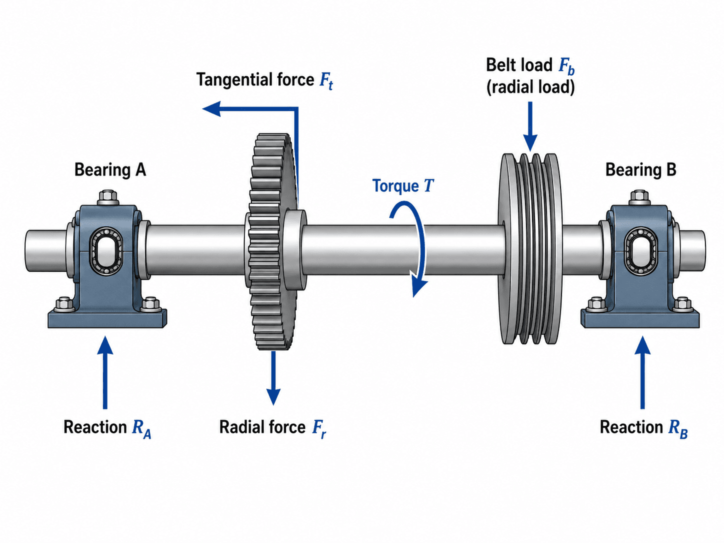
Notice that the shaft is not loaded by torque alone. The gear creates tangential and radial forces, the pulley creates a belt load, and the bearings react those loads through the shaft spans.
What Is Shaft Design?
Shaft design is a mechanical design task focused on the geometry, material, supports, and details of a shaft used to transmit rotation or power. The shaft may carry gears, pulleys, sprockets, flywheels, couplings, impellers, fans, or other rotating components. The design must provide enough strength for torque and bending, enough stiffness for alignment, and enough fatigue resistance for repeated operation.
In mechanical design, a shaft is usually different from a simple axle. A shaft commonly transmits torque, while an axle primarily supports rotating parts. The distinction matters because a power-transmitting shaft is often checked for torsion, bending, fatigue, bearing fit, keyway strength, and vibration behavior at the same time.
| Design concern | What the shaft must do | Why it matters in real machines |
|---|---|---|
| Torque transmission | Carry rotational power between components such as motors, gears, couplings, and pulleys. | Insufficient torsional capacity can cause yielding, excessive twist, keyway damage, or coupling problems. |
| Component support | Support mounted elements while transferring their loads to bearings. | Gear, belt, and chain loads create bending moments that often control shaft diameter. |
| Fatigue resistance | Survive repeated stress cycles caused by rotation, fluctuating loads, and start-stop duty. | Many shaft failures begin as small fatigue cracks at shoulders, grooves, keyways, or other local stress raisers. |
| Alignment and stiffness | Limit deflection and slope at bearings, seals, gears, and couplings. | A shaft that is strong enough can still misalign bearings or gears if it is too flexible. |
What a Shaft Must Do in a Real Machine
The design objective is to create a shaft that performs its mechanical function without becoming the weak link in the machine. That means the shaft layout, bearing locations, diameter steps, keyways, retaining features, and material must work together. The shaft also needs to be manufacturable, inspectable, and serviceable.
Torque path
Torque enters the shaft through a motor, coupling, gear, pulley, sprocket, or similar component. It then leaves the shaft through another mounted element. The shaft diameter and torque-transfer features must be sized for the transmitted torque, including overloads, shock, reversals, and duty cycle where applicable.
Bending load path
Mounted components do not only transmit torque. Spur gears create tangential and radial forces. Helical gears also create axial thrust. Belts and chains add radial loads and can create overhung bending if the pulley or sprocket sits outside the bearing span. These forces travel through the shaft to the bearings and create bending moments along the shaft length.
Geometry and assembly path
The final shaft is rarely a plain cylinder. Real shafts use shoulders to locate bearings, keyways or splines to transmit torque, grooves or rings to retain components, and fits to control assembly. Each feature helps the machine work, but each feature can also reduce fatigue strength if it creates a sharp transition or local notch.
Shaft Design Inputs Engineers Need Before Sizing
A shaft diameter calculation is only as reliable as the layout and load assumptions behind it. Before using equations, engineers define the power, speed, component locations, bearing spacing, load directions, material, surface details, operating duty, and service factor.
| Shaft design input | Why it matters | Engineering implication |
|---|---|---|
| Power and rotational speed | Power and RPM determine transmitted torque. | Low-speed shafts can see high torque even when power is moderate. |
| Gear, pulley, or sprocket forces | Mounted components create radial, tangential, and sometimes axial loads. | These loads create bearing reactions and bending moments that may control the shaft size. |
| Bearing spacing | Support locations control span length and bending moment. | Moving a bearing closer to an overhung pulley can reduce shaft bending and deflection. |
| Service factor and shock loading | Starts, stops, reversals, jams, and impact loads can raise the effective design torque. | A steady-running fan shaft may need a different design margin than a crusher, conveyor, or reversing drive. |
| Critical features | Keyways, shoulders, grooves, holes, and retaining-ring cuts create stress concentrations. | The minimum diameter is not always the most critical section; notches often control fatigue design. |
| Material and heat treatment | Strength, fatigue performance, machinability, wear, and corrosion resistance all depend on material choice. | A stronger material may not solve poor geometry, excessive deflection, or a sharp notch. |
| Duty cycle and environment | Start-stop loading, reversing torque, shock, temperature, corrosion, and contamination affect durability. | Fatigue and surface condition become more important when loading is cyclic or the environment is harsh. |
Sketch the shaft with every mounted component, bearing, shoulder, groove, keyway, and load direction before sizing. If the layout is incomplete, the calculated diameter can look precise while missing the real critical section.
Shaft Design Procedure
A useful shaft design procedure moves from layout to loads, then from strength to stiffness and detailing. The process is usually iterative because changing a bearing location, shoulder diameter, keyway, material, or gear position can change the controlling stress and deflection.
| Step | Shaft design task | Output |
|---|---|---|
| 1 | Define power, speed, rotation direction, operating duty, and shock or service factor. | Design torque and operating conditions. |
| 2 | Lay out bearings, gears, pulleys, sprockets, couplings, seals, spacers, and retaining features. | Shaft span, mounted component locations, and assembly sequence. |
| 3 | Calculate gear, belt, chain, coupling, and overhung forces. | Radial, tangential, axial, and applied loads. |
| 4 | Find bearing reactions in the required loading planes. | Support loads and load paths through the shaft. |
| 5 | Create bending moment and torque diagrams. | Critical spans and maximum combined loading locations. |
| 6 | Size the shaft for static stress and fatigue at critical sections. | Trial diameters at smooth sections, shoulders, grooves, and keyways. |
| 7 | Check deflection, slope, torsional twist, and critical speed where needed. | Stiffness, alignment, and vibration verification. |
| 8 | Finalize fillets, fits, tolerances, surface finish, heat treatment, inspection, and service access. | Manufacturable and review-ready shaft design. |
This workflow prevents the common mistake of sizing a shaft as if it were a simple torsion bar. Most practical shafts behave more like rotating beams with torque passing through them.
What Controls Shaft Diameter?
Shaft diameter is not controlled by one universal formula. The controlling design condition depends on shaft speed, torque, span length, mounted component loads, stress concentrations, stiffness requirements, and operating environment.
| Controlling condition | When it often controls | Design response |
|---|---|---|
| Torque | Low-speed, high-power shafts or compact shafts with short spans. | Increase diameter, use stronger torque-transfer features, or reduce peak torque with drive changes. |
| Bending moment | Gear, pulley, sprocket, and overhung loads create high transverse loading. | Move bearings closer to loads, increase diameter, reduce overhung distance, or change component placement. |
| Fatigue | Rotating shafts with repeated bending, fluctuating torque, keyways, shoulders, grooves, or corrosion. | Improve fillets and surface finish, reduce stress concentration, increase diameter, or revise geometry. |
| Deflection and slope | Long spans, gear mesh requirements, seal sensitivity, or bearing alignment limits. | Increase stiffness, shorten spans, move supports, or reduce applied loads. |
| Critical speed | High-speed, slender shafts or rotors with significant mounted mass. | Change stiffness, support spacing, mass distribution, or operating speed range. |
| Fits and component geometry | Bearing seats, press fits, splines, keys, collars, seals, and coupling hubs set local diameters. | Coordinate shaft diameter with standard components, tolerances, assembly method, and serviceability. |
Shaft Design Formula for Torque and Bending
Shaft design formulas are useful for preliminary sizing and design checks. They should be tied to the actual shaft layout, because the largest torque and the largest bending moment do not always occur at the same section.
Torque from power and speed
For rotating machinery, shaft torque can be estimated from transmitted power and angular speed:
If speed is given in revolutions per minute, angular speed is:
Bending and torsional stress in a solid round shaft
For a solid circular shaft, nominal bending stress and torsional shear stress are commonly estimated as:
Preliminary combined-stress check
For a basic preliminary static check, bending and torsional shear can be combined with a Von Mises-style equivalent stress:
- \(P\) Power transmitted by the shaft, commonly in watts, kilowatts, or horsepower.
- \(N\) Rotational speed, commonly in revolutions per minute.
- \(T\) Torque transmitted through the shaft section, commonly in N·m, lb·ft, or lb·in.
- \(M\) Bending moment at the shaft section, commonly in N·m or lb·in.
- \(d\) Solid shaft diameter at the section being checked.
- \(\sigma_{eq}\) Equivalent stress used for a preliminary combined bending and torsion check.
These equations do not automatically account for stress concentrations, fatigue notch sensitivity, surface finish, size effects, heat treatment, corrosion, residual stress, misalignment, or critical speed. They are starting points, not the full shaft design.
Shaft Design for Fatigue Loading
Fatigue is one of the most important shaft design checks because many shafts operate through millions of stress cycles. A rotating shaft under a steady transverse load can still experience alternating bending stress at a material point as the shaft turns. Torque may be steady, fluctuating, or reversing depending on the machine duty.
Alternating bending and mean torque
A gear or pulley load can create a bending moment that is fixed in space, while the shaft material rotates through that stress field. That can make bending stress alternate even when the external load is steady. Torsional stress may behave differently if the torque is steady, pulsing, reversing, or shock-loaded.
Fatigue modifiers and notch effects
Real fatigue checks may account for surface finish, size factor, reliability, temperature, material strength, mean stress, stress concentration, and fatigue notch sensitivity. A shoulder, groove, or keyway can reduce fatigue strength enough that it controls the design even when the smooth-shaft nominal stress looks acceptable.
Goodman, Soderberg, and ASME-style checks
Different design references use different approaches to combine alternating and mean stresses. The practical goal is the same: compare the actual cyclic stress state against an allowable fatigue condition with an appropriate design factor. For top-ranking usefulness, the important takeaway is that shaft fatigue is usually a section-by-section check, not a single global diameter decision.
If a shaft has a keyway or shoulder in a high-bending region, check that section for fatigue using the local diameter, the local moment and torque, and the stress concentration effect of the feature.
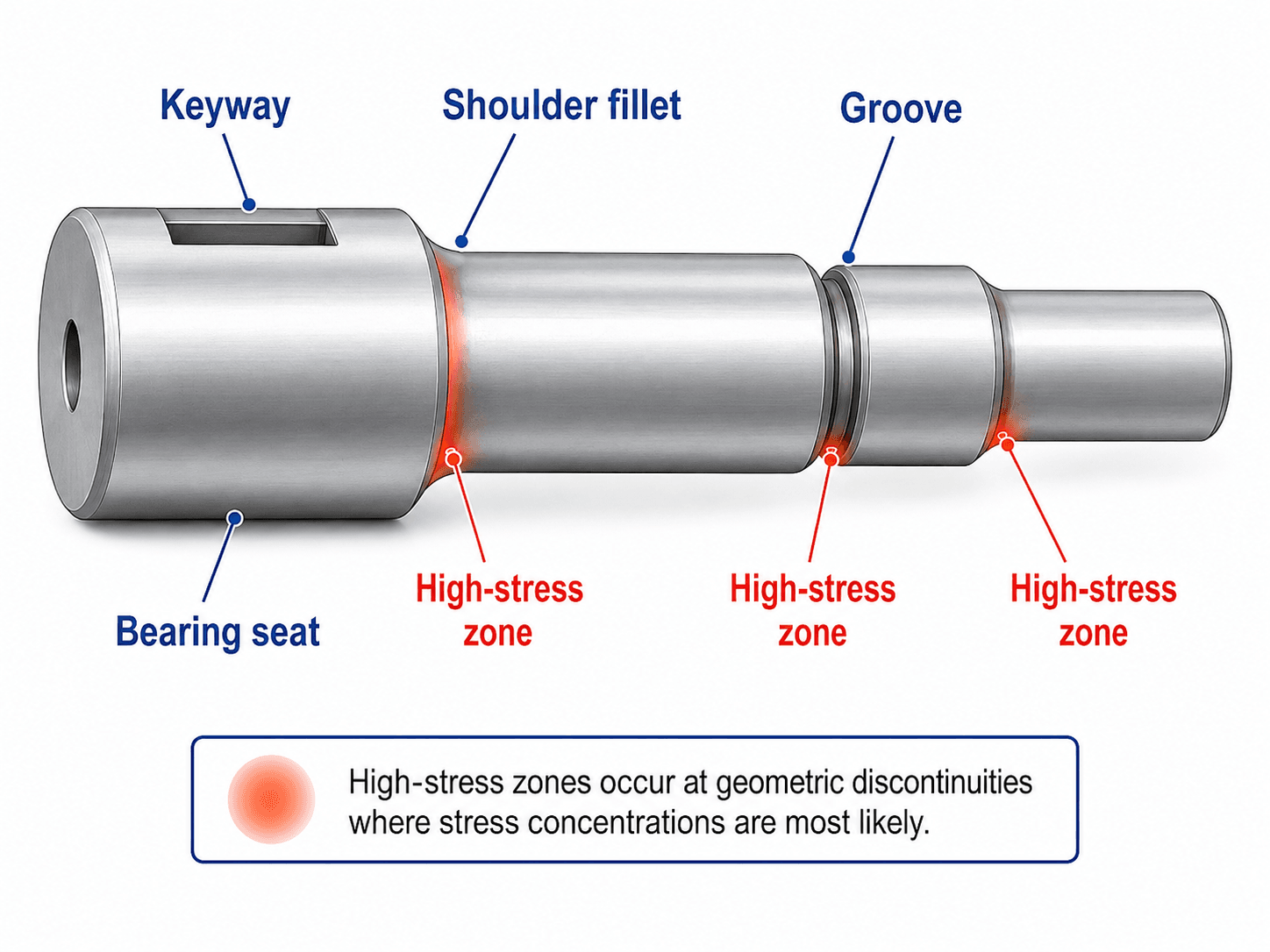
Critical Sections and Stress Concentration Zones
Shaft failures often begin at local geometric discontinuities rather than at the visually largest part of the shaft. A shoulder fillet, keyway, snap-ring groove, cross-hole, undercut, or abrupt diameter change can raise local stress and become the fatigue crack initiation location.
Why keyways and shoulders are important
A keyway helps transmit torque between a shaft and a hub, but it removes material and creates notch geometry. A shoulder helps position a bearing, gear, or spacer, but a sharp shoulder creates a local stress riser. Increasing the fillet radius, improving surface finish, avoiding unnecessary grooves, and placing features away from high bending regions can improve fatigue performance.
Separate shaft, key, and hub checks
A keyway creates more than one design question. The shaft must be checked for stress concentration and fatigue at the keyway. The key itself must be checked for shear and bearing stress. The hub must also have enough material and contact length to transfer torque without crushing, fretting, or cracking.
What the design review should check
The review should identify the bending moment and torque at each discontinuity, not just at the midpoint of the shaft. A smaller diameter section with a keyway can be more critical than a larger smooth section with a higher nominal load.
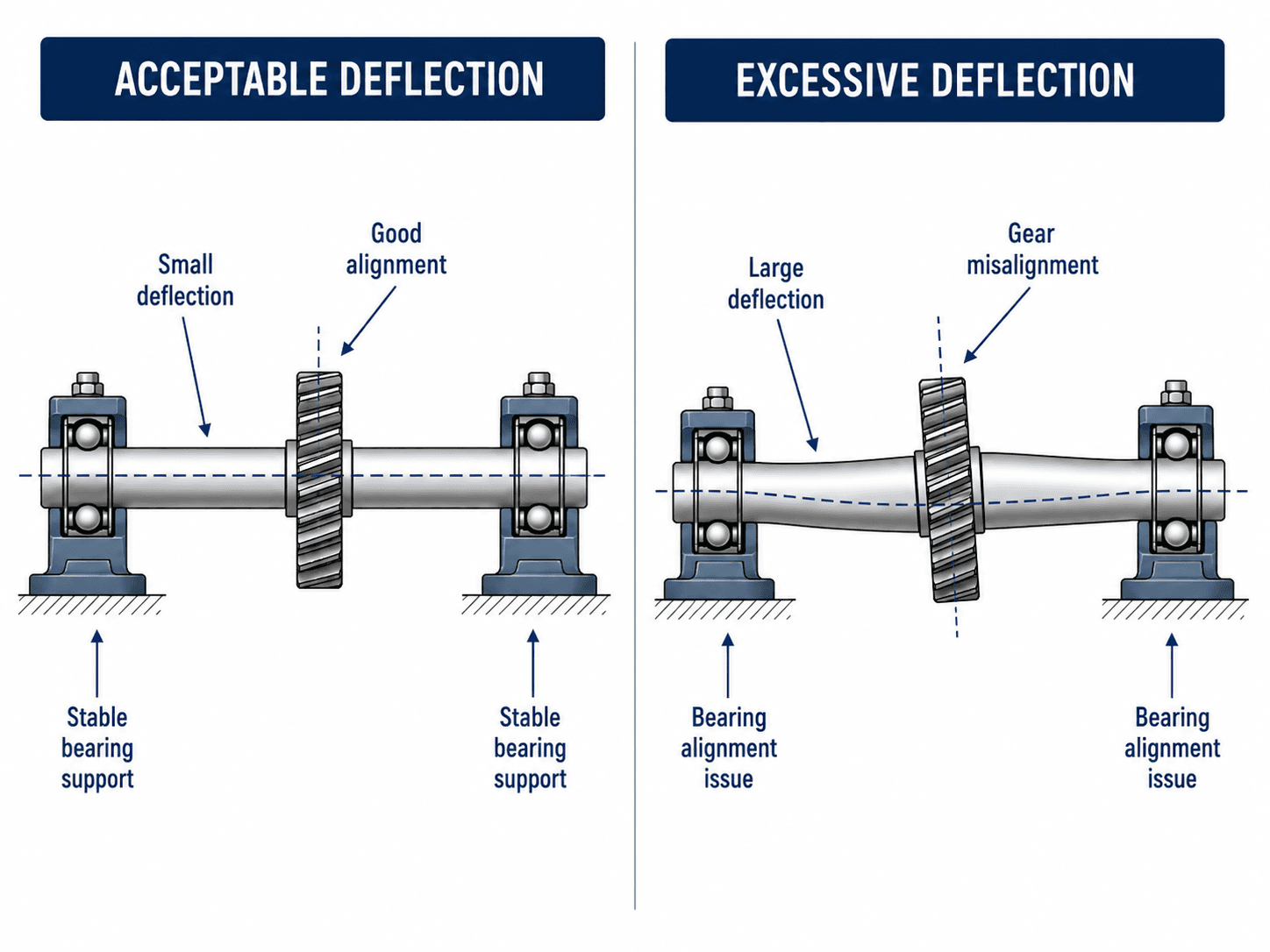
Deflection, Alignment, and Critical Speed
Strength is only one part of shaft design. Shafts also need enough stiffness to keep bearings, seals, gears, and couplings aligned. Excessive deflection can overload bearings, reduce gear mesh quality, increase noise, damage seals, and create vibration even when the shaft is not close to yielding.
Deflection and slope
Deflection is the vertical or lateral displacement of the shaft under load. Slope is the angular rotation of the shaft centerline at a location. Both matter: gear mesh, bearing life, seal contact, and coupling alignment can be sensitive to slope even when total deflection looks small.
Torsional twist
Long shafts can twist noticeably under torque. Torsional twist may affect timing, positioning accuracy, coupling behavior, or control response in machinery. A larger diameter, shorter shaft span, hollow shaft optimization, or different material may be considered depending on the design goal.
Critical speed
Critical speed is the rotational speed where shaft flexibility, mass distribution, and support stiffness can produce large vibration response. High-speed or slender shafts should be checked so normal operating speed is safely separated from the shaft’s critical speed range.
Shaft Materials, Fits, and Design Tradeoffs
Shaft material selection is not just a strength decision. Engineers also consider machinability, heat treatment, wear, corrosion resistance, surface finish, distortion risk, availability, cost, and compatibility with bearings, seals, keys, splines, and hubs.
| Design choice | Why it matters | Typical shaft design tradeoff |
|---|---|---|
| Carbon steel shaft | Common choice for general power transmission and machined shafts. | Usually economical and machinable, but may need surface protection in corrosive service. |
| Alloy steel or heat-treated shaft | Used when higher strength, wear resistance, or fatigue performance is needed. | Can improve capacity but may increase cost, distortion risk, and manufacturing control requirements. |
| Stainless steel shaft | Useful where corrosion, washdown, or cleanliness matters. | May have different fatigue, galling, cost, and machinability considerations than carbon steel. |
| Press fits, keys, and splines | Control how torque is transferred from shaft to hub. | They must be checked with hub strength, stress concentrations, assembly force, and serviceability in mind. |
| Fillets, grooves, and retaining features | Help locate components but interrupt shaft geometry. | Need enough radius, clearance, surface finish, and fatigue review to avoid local failures. |
| Bearing seats and tolerances | Set the interface between shaft and bearing inner race. | Incorrect fits can cause creep, fretting, assembly damage, excess preload, or bearing-life reduction. |
A larger diameter improves strength and stiffness quickly, but it can increase bearing size, gear hub size, weight, cost, seal size, and inertia. Shaft design is often a packaging and system-level tradeoff, not a single-part optimization.
Solid Shaft vs Hollow Shaft Design
Solid shafts are common because they are simple to machine and easy to specify. Hollow shafts can be more efficient when weight, torsional stiffness, inertia, or packaging matters. The better choice depends on the load path, manufacturing method, connection details, and cost target.
| Comparison point | Solid shaft | Hollow shaft |
|---|---|---|
| Manufacturing simplicity | Usually easier to machine, inspect, and source. | May require boring, tubing, welding, or more controlled manufacturing. |
| Weight and inertia | Heavier for the same outside diameter. | Can reduce weight and rotational inertia. |
| Torsional efficiency | Good for general-purpose shafts. | Can be efficient because outer material contributes strongly to torsional stiffness. |
| Connections and features | Keyways, shoulders, threads, and bearing seats are often straightforward. | Connection details may be more complex, especially near hubs, splines, or welded regions. |
| Typical use case | General machinery, moderate-speed drives, and common power transmission. | Applications where weight, stiffness-to-mass ratio, or packaging efficiency is important. |
Shaft Diameter Calculation Example
A preliminary shaft diameter calculation helps show how torque and bending work together. Assume a solid steel shaft transmits \(5 \, \text{kW}\) at \(600 \, \text{rpm}\). A mounted pulley and gear create a maximum bending moment of \(180 \, \text{N}\cdot\text{m}\) at a critical smooth section. Use a simplified allowable equivalent stress of \(80 \, \text{MPa}\) for the preliminary check.
Step 1: Estimate torque
Convert rotational speed to angular speed:
Then calculate transmitted torque:
Step 2: Combine bending and torsion
For a preliminary solid-shaft check:
Step 3: Solve for trial diameter
Substitute \(M = 180 \, \text{N}\cdot\text{m}\), \(T = 79.6 \, \text{N}\cdot\text{m}\), and \(\sigma_{eq} = 80 \, \text{MPa}\). Solving for \(d\) gives:
A practical preliminary selection would likely round up to a standard size such as \(30 \, \text{mm}\), then continue with fatigue, stress concentration, keyway, bearing-seat, deflection, and critical-speed checks.
The example shows why bending matters. The torque is about \(79.6 \, \text{N}\cdot\text{m}\), but the bending moment is \(180 \, \text{N}\cdot\text{m}\), so a torque-only calculation would understate the design demand.
Common Shaft Failure Modes
Shaft failures usually trace back to a missed load, an underestimated stress concentration, excessive deflection, poor fit, or a service condition that was not included in the design assumptions.
| Failure mode | Typical cause | Design prevention |
|---|---|---|
| Fatigue crack at shoulder | Sharp fillet, high bending moment, cyclic loading, poor surface finish. | Use larger fillets, improve finish, reduce bending, check fatigue, and avoid placing shoulders at high-stress sections. |
| Keyway crack | Stress concentration from keyseat geometry combined with torque and bending. | Check the keyed section, use proper key length, improve geometry, or consider splines or other torque-transfer methods. |
| Excessive twist | Long shaft, high torque, insufficient polar stiffness. | Increase diameter, shorten shaft length, use a hollow shaft where efficient, or change drivetrain layout. |
| Bearing misalignment | Excessive shaft slope or deflection at bearing locations. | Reduce span, move bearings, increase stiffness, improve housing alignment, or reduce overhung loading. |
| Critical speed vibration | Operating speed too close to a shaft or rotor natural frequency. | Check critical speed, revise support stiffness, change mass distribution, or shift operating speed range. |
| Fretting at fit | Micro-motion at a hub, bearing seat, coupling, or press-fit interface. | Review fit class, surface finish, retention method, torque transfer, alignment, and lubrication conditions. |
Senior Engineer Shaft Design Review Checklist
The most useful shaft design check is a review that asks whether the shaft works as a complete machine element. The checklist below is designed to catch the issues that formula-only shaft sizing often misses.
| Review area | What to look for | Why it matters |
|---|---|---|
| Layout and assembly | Bearings, gears, pulleys, spacers, seals, retaining rings, keyways, and installation direction are all shown. | A shaft can be strong but impossible or expensive to assemble if the sequence is not considered. |
| Load path | Torque, gear loads, belt loads, axial thrust, overhung loads, and bearing reactions are included. | Missing a radial or overhung load can dramatically understate bending moment. |
| Critical sections | Stress is checked at shoulders, grooves, keyways, bearing seats, and high-moment sections. | Fatigue cracks often start at local geometry changes, not necessarily at the largest nominal stress section. |
| Fatigue and duty cycle | Alternating bending, fluctuating torque, shock, reversals, starts, stops, and surface condition are considered. | Rotating shafts commonly fail by fatigue long before a simple static yield check would predict a problem. |
| Stiffness and alignment | Deflection and slope are acceptable at bearings, seals, gears, couplings, and critical mounted components. | Misalignment can reduce bearing life, increase vibration, and cause gear mesh problems. |
| Torque-transfer details | Keys, splines, press fits, shrink fits, pins, and clamping features are checked with the hub and shaft together. | A shaft can pass stress checks while the key, hub, or fit becomes the actual weak point. |
| Manufacturing details | Fillet radii, surface finish, tolerances, heat treatment, grinding, and inspection requirements are realistic. | Small detailing choices can control fatigue strength, cost, and repeatability. |
| Service and maintenance | Components can be removed, bearings can be serviced, and wear surfaces can be inspected. | Maintenance access affects lifecycle cost and field reliability. |
Engineering Judgment and Field Reality
Textbook shaft problems often show clean spans, simple point loads, and one neat diameter. Real shafts are less ideal. Loads may be uncertain, belts may be over-tensioned, couplings may be misaligned, keys may fret, and bearings may be mounted in housings with imperfect stiffness. Good shaft design accounts for the machine around the shaft.
If a shaft keeps failing near the same shoulder, keyway, or groove, replacing it with the same geometry in a stronger material may not fix the root cause. The real issue may be a stress concentration, misalignment, overhung load, inadequate fillet radius, poor surface finish, or unexpected vibration.
Experienced designers also pay attention to how the shaft will be manufactured and measured. Bearing seats may require tight tolerances and controlled surface finish. Fillets must clear bearing chamfers. Keyways must match hub and key standards. A small interference fit mistake can turn a manageable design into an assembly problem or a bearing-life problem.
When This Breaks Down
Simplified shaft design methods become less reliable when the geometry, loading, speed, or service environment moves beyond the assumptions of basic beam-and-torsion calculations.
- High-speed or slender shafts may require rotor dynamics and critical-speed analysis instead of only static strength checks.
- Strong shock, torque reversal, start-stop cycling, or variable-speed duty may require fatigue analysis based on actual loading history.
- Complex shoulders, grooves, cross-holes, splines, press fits, and welds may need more detailed stress concentration evaluation.
- Corrosion, fretting, poor lubrication, abrasive contamination, and temperature effects can reduce fatigue life and surface performance.
- Very tight gear, seal, or bearing alignment requirements can make deflection and slope more important than nominal stress.
Common Shaft Design Mistakes and Practical Checks
The most common shaft design mistakes happen when a designer uses a clean formula but misses the messy machine details that drive real failures. The practical checks below help prevent those errors.
- Using torque-only sizing: always check bending from gears, pulleys, sprockets, and overhung components.
- Ignoring keyway and shoulder stress concentrations: check fatigue at geometric discontinuities, not only at smooth shaft sections.
- Forgetting deflection: verify shaft slope and displacement at bearings, seals, gears, and couplings.
- Placing bearings too far from loads: long spans and overhung loads increase bending moment and deflection.
- Choosing material without considering manufacturing: heat treatment, surface finish, grinding, tolerances, and fit requirements can control the final design.
- Skipping assembly review: make sure each component can actually be installed, retained, adjusted, and removed.
Do not calculate one shaft diameter and apply it everywhere without checking each critical section. A shaft with multiple shoulders, grooves, keyways, and bearing seats needs section-by-section review.
Engineering References and Design Guidance
Shaft design is often supported by company standards, machine-design handbooks, bearing and coupling manufacturer data, and formal shaft or axle load-capacity standards. These references are especially useful when fatigue, stress concentration, material strength, and notched geometry must be evaluated more rigorously.
- DIN 743 shaft and axle load-capacity standard series: DIN 743-2 theoretical stress concentration factors and fatigue notch factors is part of a recognized shaft and axle load-capacity standard family used for more formal treatment of fatigue-relevant geometry effects.
- Project-specific criteria: final shaft details may also be controlled by owner specifications, manufacturer requirements, bearing fit tables, coupling limits, gear design requirements, inspection criteria, and machine safety requirements.
- Engineering use: references help turn a preliminary shaft diameter into a detailed design by addressing fatigue modifiers, notch effects, material data, fits, tolerances, and verification methods.
Frequently Asked Questions
Shaft design is the process of sizing and detailing a shaft so it can transmit torque, support mounted components, resist bending and fatigue, limit deflection, and operate without excessive vibration or misalignment.
No. Torque is important, but many shafts are controlled by combined bending and torsion, fatigue at shoulders or keyways, deflection at gears and bearings, or critical-speed limits rather than torque alone.
Keyways, shoulders, grooves, and retaining-ring cuts interrupt the smooth shaft geometry. Those discontinuities raise local stress and can become fatigue crack initiation points under repeated bending or torsion.
A shaft usually transmits torque and power between rotating machine elements, while an axle primarily supports rotating components or wheels. In real machines, the terms can overlap when a member both supports load and transmits torque.
Shaft diameter can be controlled by torque, bending moment, fatigue at stress concentrations, deflection, torsional twist, critical speed, or the geometry required for bearings, gears, keys, splines, and couplings.
Summary and Next Steps
Shaft design is the mechanical design process used to create a shaft that can transmit torque, carry mounted components, resist bending and fatigue, maintain alignment, and operate reliably inside a real machine.
The strongest shaft designs start with the load path, then check torque, bending, fatigue, critical sections, material choice, deflection, critical speed, assembly, and serviceability. The most important practical lesson is that shoulders, keyways, grooves, bearing spacing, and machine alignment can control the design as much as the shaft diameter itself.
Where to go next
Continue your learning path with related Turn2Engineering resources.
-
Mechanical Components
Understand how gears, bearings, shafts, keys, couplings, and other parts work together in mechanical assemblies.
-
Torque Calculator
Estimate torque from force, lever arm, power, and RPM before using it in shaft sizing or drivetrain review.
-
Failure Mechanisms
Learn how fatigue, fracture, wear, corrosion, and overload contribute to real mechanical failures.