
Direct Answer
Bearing selection is the engineering process of choosing a bearing type, size, and arrangement that can carry the actual radial and axial loads at the required speed and life while also satisfying stiffness, alignment, lubrication, temperature, contamination, fit, clearance, mounting, and maintenance constraints.
The correct workflow is: define the application and load path, choose a bearing family and arrangement, calculate equivalent bearing load and rating life, check static capacity and speed, then verify lubrication, sealing, shaft and housing fits, operating clearance, mounting, and field conditions against the exact manufacturer catalog. A bearing that passes the L10 calculation can still fail early if those system-level checks are wrong.
Bearing Selection Workflow: What to Decide and in What Order
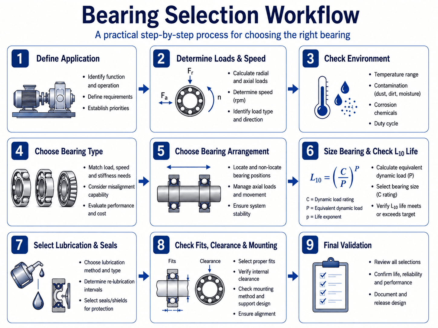
The fastest way to make a poor bearing choice is to begin with a catalog part number. Start with the machine instead: what must rotate, what loads act on the shaft, how accurately it must run, and what environment the bearing must survive.
Radial and axial loads, load direction, shaft speed, duty cycle, desired service life, shaft diameter, available envelope, temperature, contamination, and maintenance access.
Bearing family, locating/non-locating or paired arrangement, preliminary size, lubrication method, seal concept, and internal-clearance strategy.
Equivalent dynamic load, L10 life, static safety, speed capability, fits, operating clearance, thermal expansion, mounting method, inspection, and exact catalog limits.
-
Define the machine requirement.
Identify function, shaft motion, service hours, reliability target, maintenance strategy, environment, available shaft/housing envelope, and acceptable downtime.
-
Calculate bearing reactions.
Resolve radial, axial, combined, reversing, overhung, shock, and moment-producing loads at the bearing locations—not merely the externally applied machine load.
-
Choose a bearing family and arrangement.
Match load direction, speed, stiffness, misalignment tolerance, axial-location needs, thermal growth, and packaging.
-
Size and validate the bearing.
Use manufacturer data for equivalent dynamic load, basic rating life, static capacity, speed, lubrication, fits, clearance, seals, mounting, and other application-specific limits.
Selection-process basis: SKF — Bearing selection process identifies loads, precision and stiffness, speed, temperature, vibration, contamination, lubrication, fits, internal clearance, sealing, mounting, and other operating conditions as linked selection decisions.
Bearing Types by Load Direction, Speed, Stiffness, and Misalignment
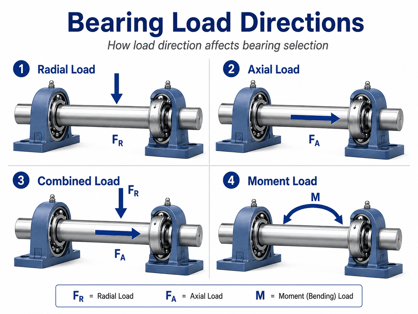
Load direction narrows the bearing family, but it does not finish the selection. Speed, stiffness, misalignment, available space, friction, and whether axial load reverses can change the best choice.
Start by calculating the load reactions at each support. A pulley, belt, gear, chain, impeller, coupling, rotor weight, or process force can produce radial reaction. Helical gears, pumps, screws, fans, and process thrust can add axial load. An overhung load can increase support reactions through bending even when the external force itself is moderate.
| Bearing Family | Load Capability | Relative Strength | Typical Selection Reason | Important Limitation to Check |
|---|---|---|---|---|
| Deep groove ball | Radial plus limited-to-moderate axial capability depending on the exact bearing and operating condition. | Low friction, broad speed capability, simple packaging. | General-purpose motors, fans, light gearboxes, pumps, and compact rotating machinery. | Misalignment, shock, sustained thrust, fit-induced clearance loss, seal friction, and exact axial-load limits. |
| Angular contact ball | Combined radial and axial load with direction determined by contact angle and arrangement. | High speed, axial stiffness, preload capability. | Spindles, pumps, gear shafts, precision rotation, and combined-load applications. | Axial-load direction, pair arrangement, preload, thermal behavior, mounting accuracy, and lubrication. |
| Cylindrical roller | High radial load; axial capability depends strongly on internal design. | High radial capacity and stiffness. | Gearboxes, motors, industrial shafts, and applications with high radial demand. | Misalignment, flange loading, axial capability, minimum load, and arrangement-specific displacement behavior. |
| Tapered roller | Combined radial and axial load. | High stiffness, adjustable endplay/preload, strong combined-load capability. | Vehicle hubs, gearboxes, wheels, heavy shafts, and paired bearing systems. | Adjustment, induced axial load, preload/endplay, lubrication, mounting geometry, and heat generation. |
| Spherical roller | High radial and substantial axial load with self-aligning capability. | Heavy load, shock tolerance, misalignment accommodation. | Fans, conveyors, crushers, vibrating equipment, and flexible industrial structures. | Speed, friction, lubrication, minimum load, axial-load magnitude, and actual misalignment limits. |
| Needle roller | High radial capacity in a small radial envelope. | Compact cross-section. | Transmissions, linkages, compact gearboxes, and space-constrained radial support. | Raceway surface requirements, alignment, shaft hardness/finish, lubrication, and separate axial support. |
| Thrust bearing | Primarily axial load; capability depends on thrust-bearing type. | Purpose-built axial support. | Vertical shafts, screws, turntables, and dedicated thrust positions. | Radial-load capability, speed, lubrication, alignment, and whether thrust reverses direction. |
| Plain bearing / bushing | Application-dependent radial or thrust sliding support. | Simple construction, oscillating/low-speed capability, dirt tolerance in some designs. | Pivots, joints, low-speed equipment, shock-prone or compact mechanisms. | PV limits, wear, lubrication, heat, shaft finish/hardness, material compatibility, and clearance. |
Swipe horizontally to view all table columns.
Radial and axial load must be evaluated together
For many radial bearings, the equivalent dynamic bearing load is not simply the radial reaction. Manufacturer equations combine radial and axial components using bearing-specific factors. SKF gives the general form P = XFr + YFa, where X and Y depend on the bearing type and operating condition. Do not invent X and Y or transfer them between bearing series.
Bearing spacing can be more valuable than oversizing
When an overhung pulley, gear, fan, or wheel creates high bearing reactions, changing the shaft layout can reduce bearing load before a larger bearing is considered. Moving the external load closer to the support or increasing effective support spacing can reduce reactions and shaft deflection. Use the Shaft Design guide when bearing selection and shaft reactions must be solved together.
Load-combination basis: SKF — Equivalent dynamic bearing load, P explains the bearing-specific use of radial and axial load factors in equivalent dynamic load calculations.
Locating, Non-Locating, and Paired Bearing Arrangements
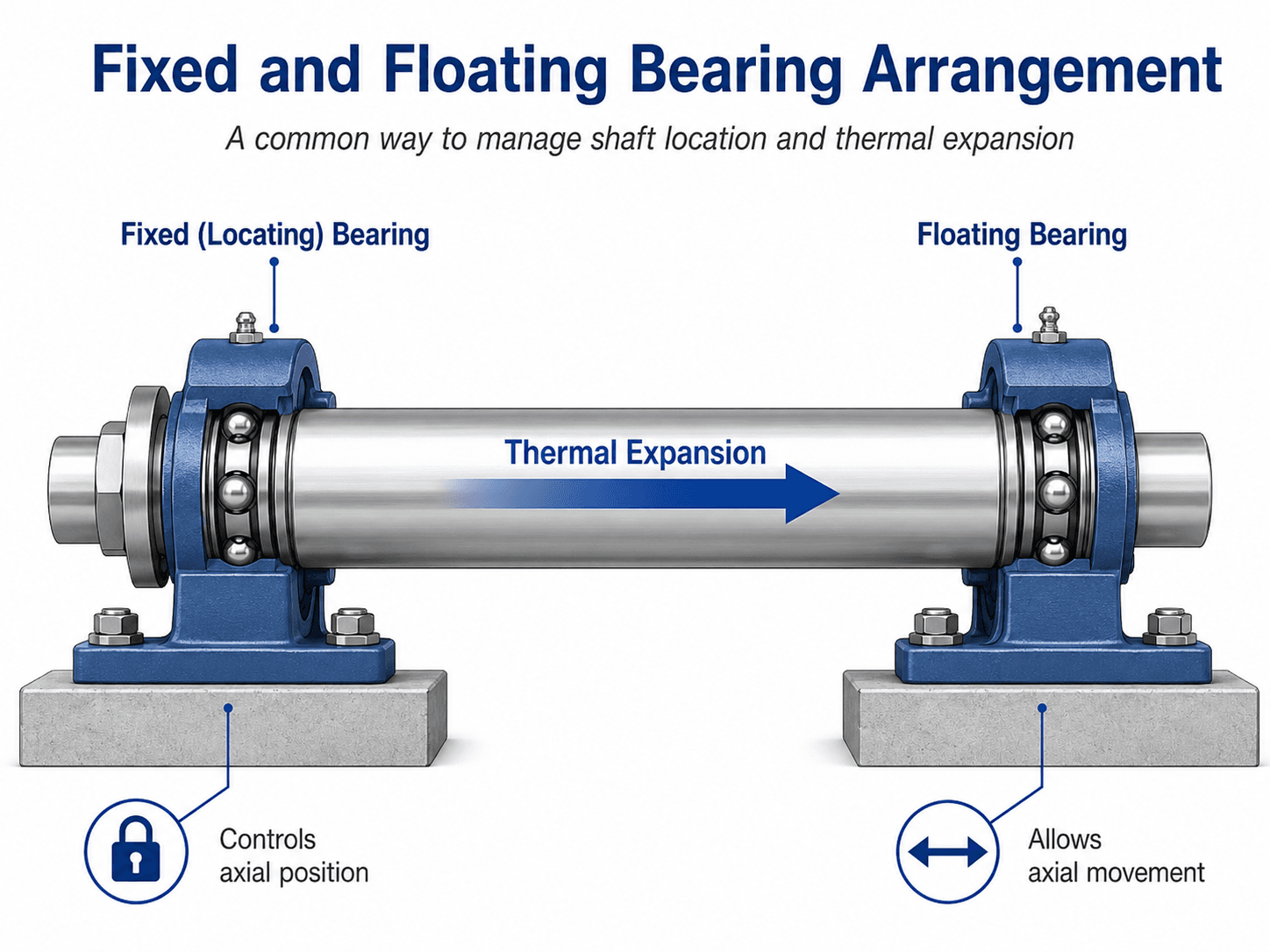
A bearing arrangement must support the radial load and control shaft position without unintentionally locking thermal expansion or creating an axial load path the bearings were not selected to carry.
Locating bearing position
The locating bearing position establishes the shaft’s axial position relative to the housing and may carry axial load in one or both directions. The bearing type, shoulders, locknuts, covers, spacers, retaining rings, and mating components must all support the intended axial load path.
Non-locating bearing position
The non-locating position supports radial load but permits axial displacement caused by shaft/housing temperature difference or dimensional change. SKF notes that this support accommodates axial displacement when thermal expansion changes the distance between bearing positions. If both supports are inadvertently axially locked, thermal growth can generate additional axial load or preload.
Paired angular-contact or tapered arrangements
Paired bearings are often used for bidirectional axial support, stiffness, preload control, or moment resistance. Back-to-back, face-to-face, and tandem arrangements do not behave the same way. Bearing contact angle, pair orientation, preload/endplay, shaft/housing rigidity, and thermal gradients must be evaluated with the exact product data.
Do not assume that calling one end “floating” makes it free to move. Interference fits, corrosion, housing distortion, shoulder geometry, seals, or friction can prevent the intended axial displacement. Verify how the non-locating function is physically achieved.
Arrangement basis: SKF — Arrangements and their bearing types distinguishes locating and non-locating positions and explains the role of axial displacement caused by shaft/housing thermal expansion.
Bearing Life, Equivalent Load, and Static Capacity Checks
Basic rating life is a fatigue calculation for rolling bearings under defined assumptions. ISO 281:2007 remains the published ISO standard for dynamic load ratings and rating life as of August 2026, while ISO is developing a revision. ISO specifies basic rating life at 90% reliability and also provides methods for modified rating life that consider additional operating influences.
1. Determine equivalent dynamic bearing load
For combined radial and axial loading, the exact load equation is bearing-specific. A common general form is:
- PEquivalent dynamic bearing load, force units such as N or kN.
- FrRadial load acting at the bearing, same force units as P.
- FaAxial load acting at the bearing, same force units as P.
- X, YDimensionless radial and axial load factors taken from the exact bearing manufacturer’s data and applicable load-ratio rules.
2. Calculate ISO basic rating life
For a bearing operating under a constant equivalent dynamic load, the familiar basic rating-life relationship is:
For conventional basic-life calculations, p = 3 for ball bearings and p = 10/3 for roller bearings. Keep C and P in the same force units.
- L10Basic rating life in millions of revolutions associated with 90% reliability under the standard’s assumptions.
- L10hBasic rating life converted to operating hours at constant speed.
- CBasic dynamic load rating from the exact bearing catalog, same force units as P.
- pLife exponent: 3 for ball bearings and 10/3 for roller bearings in the basic ISO relationship.
- nRotational speed in revolutions per minute.
3. Check static load separately
Basic fatigue life does not protect against permanent deformation under high static or peak load. Use the exact manufacturer’s equivalent static-load method and basic static load rating C0. A commonly used static safety-factor form is:
The acceptable static safety factor depends on bearing type, rotation/oscillation, shock, noise and precision requirements, and manufacturer guidance. Do not publish or apply one universal minimum s0 to every machine.
Basic rating life is not field service life
ISO 281 explicitly separates fatigue-rating calculations from failure modes such as wear, corrosion, and electrical erosion. Lubrication, contamination, temperature, mounting, fits, internal clearance, alignment, seals, shock, and electrical current can make real service life much shorter than a basic L10 result. Use modified-life methods or manufacturer application tools when the application requires a more realistic life model.
Rating-life basis: ISO 281:2007 — Rolling bearings — Dynamic load ratings and rating life defines basic dynamic load ratings and basic rating life at 90% reliability and also addresses modified rating life. SKF’s size selection based on rating life provides application guidance consistent with ISO 281.
Fits, Internal Clearance, Lubrication, Seals, Speed, and Mounting
The catalog bearing is only one component of the bearing system. Shaft and housing fits, operating clearance, lubricant, seals, temperature, speed, shoulders, and mounting force can determine whether a correctly sized bearing survives.
| Design Check | What Can Go Wrong | What to Verify | Catalog / Design Input |
|---|---|---|---|
| Shaft and housing fits | Ring creep, fretting, cracked rings, difficult mounting, or excessive clearance reduction. | Which ring sees rotating load, load magnitude/direction, material, temperature, surface finish, geometry, and mounting method. | Manufacturer fit tables and actual shaft/housing tolerance stack. |
| Internal clearance / preload | Too little operating clearance can create heat and preload; too much can reduce stiffness and increase vibration/noise. | Initial clearance, interference-fit reduction, temperature difference, preload method, and required operating clearance. | Bearing clearance class, fit calculation, thermal condition, application guidance. |
| Lubrication | Film starvation, excessive churning, high temperature, wear, corrosion, or short grease life. | Grease/oil type, viscosity, speed, load, temperature, relubrication method, quantity, compatibility, and cleanliness. | Manufacturer lubrication guidance and lubricant supplier data. |
| Sealing | Contamination ingress, lubricant loss, excess friction, pressure buildup, or seal wear. | Dust, water, washdown, chemicals, pressure, shaft speed, seal contact, labyrinth/purge strategy, and maintenance. | Integral seal/shield options and housing-seal design. |
| Speed and temperature | Heat generation, lubricant degradation, cage problems, seal overheating, and clearance change. | Reference/limiting speeds, actual lubrication method, bearing load, ambient temperature, heat removal, and seal type. | Exact product speed data and application-specific thermal check. |
| Misalignment | Edge loading, heat, reduced fatigue life, seal problems, and unstable load distribution. | Shaft deflection, housing alignment, base distortion, bearing self-aligning capability, and installation tolerance. | Shaft-analysis results and manufacturer’s permissible misalignment guidance. |
| Mounting | Brinelling, seal damage, ring cracking, contamination, cocked installation, or incorrect preload. | Force path, press/heating method, shoulder radii, mounting tools, cleanliness, retained clearances, and dismounting access. | Manufacturer mounting instructions and component drawing. |
Swipe horizontally to view all table columns.
Fit and clearance must be solved together
An interference fit can expand an inner ring or compress an outer ring and reduce internal clearance. Temperature differences between rings can change it again in operation. That means a bearing selected with “normal” internal clearance can run too tightly if the fit and thermal condition are ignored. The required clearance class is therefore application-specific.
Contamination control can dominate life
Increasing C does not solve a contaminated lubricant. If the machine operates in abrasive dust, moisture, washdown, process debris, or corrosive exposure, sealing and lubricant cleanliness can control service life more strongly than a modest change in dynamic rating.
Mounting force must pass through the ring being fitted
When pressing a bearing onto a shaft, force should be applied to the ring receiving the interference fit; when pressing into a housing, the load path should act through the outer ring. Forcing an interference fit through balls or rollers can indent raceways and damage a new bearing before the machine starts.
These choices also affect manufacturability and serviceability. Use the Design for Manufacturing guide to review shoulders, fits, tool access, inspection, assembly, and bearing replacement before the housing is released.
Worked Bearing Selection Example: Preliminary Ball-Bearing Life Check
Example problem
A continuously rotating shaft uses a candidate ball bearing after the shaft-reaction analysis and manufacturer load-factor calculation have already produced an equivalent dynamic bearing load. Assume C = 9.5 kN, P = 1.8 kN, and n = 1,750 rpm. The values are instructional assumptions, not a recommendation for a particular bearing series or machine.
Calculate basic rating life in revolutions
This establishes the ISO basic fatigue-life result before converting it to hours.
Convert the life to operating hours
Hours are easier to compare with a machine’s required duty and maintenance interval.
Interpret the result before selecting the bearing
A life number is useful only when compared with the required duty and the other bearing-system constraints.
C/P = 9.5/1.8 ≈ 5.28; cubing 5.28 gives about 147, so the order of magnitude is consistent.
P is assumed to have already been calculated with the correct manufacturer factors. This example does not establish X, Y, e, static safety, or modified life.
Compare required machine life with the result, then verify C0/P0, speed, lubrication, seals, fit, clearance, and exact product limits.
Because basic ball-bearing life varies with the cube of C/P, reducing equivalent load can be extremely valuable. Before jumping several bearing sizes, check whether pulley overhang, belt force, gear location, shaft deflection, or bearing spacing can be improved.
Why Bearings Fail Even When the Load Rating Looks Adequate
Repeated bearing failure usually means the limiting mechanism is not the catalog dynamic rating. Failure evidence should be traced back to lubrication, contamination, fit, clearance, alignment, mounting, electrical current, thermal growth, or the actual load path.
| Observed Symptom | Possible Causes | Evidence to Check | Design / Maintenance Response |
|---|---|---|---|
| High temperature | Insufficient operating clearance, excessive preload, excess lubricant, wrong viscosity, overload, seal friction, misalignment. | Temperature trend, grease quantity, fit data, internal-clearance calculation, shaft/housing alignment, load estimate. | Correct the cause before upsizing; a larger bearing can still overheat under the same system error. |
| Early noise / vibration | Mounting damage, contamination, brinelling, poor lubrication, misalignment, looseness. | Raceway marks, lubricant cleanliness, installation history, fit surfaces, vibration signature, shaft runout. | Improve mounting, cleanliness, fit, alignment, or storage/handling as indicated by evidence. |
| Fretting or creep at a ring seat | Fit too loose for the load condition, ring movement, vibration, unsuitable seat finish. | Shaft/housing marks, dimensional inspection, load direction, ring rotation relative to load, surface condition. | Re-evaluate manufacturer fit recommendations and the actual load condition. |
| Short fatigue-like life | Actual P higher than assumed, contamination, poor film, misalignment, shock, excessive preload. | Reaction calculation, duty cycle, lubricant analysis, seal condition, alignment, clearance, failure morphology. | Correct the load model and system conditions before selecting a higher C value. |
| Electrical fluting / erosion | Current passing through the bearing in motor or drive applications. | Characteristic raceway pattern, drive/grounding configuration, shaft voltage/current measurements. | Use appropriate grounding, insulated bearing solutions, filtering, or manufacturer-supported electrical protection. |
| Repeated seal or lubricant contamination | Wrong seal concept, shaft runout, pressure/washdown, damaged sealing surface, ineffective purge strategy. | Seal wear pattern, ingress path, shaft finish/runout, housing pressure, maintenance practice. | Redesign the sealing system rather than treating contamination as a bearing-capacity problem. |
Swipe horizontally to view all table columns.
Temperature, noise, vibration, and discoloration can have multiple causes. Preserve failed components and lubricant when possible, document installation and operating conditions, and use a structured damage-analysis method before changing the bearing design.
Damage-analysis context: SKF — Root Cause Bearing Damage Analysis treats operating environment, moisture/contamination, maintenance, lubrication, and application conditions as part of bearing-damage diagnosis rather than assuming overload is the only cause.
Senior Engineer Bearing Selection Checklist
Use this final review after a candidate bearing and arrangement have been identified. A missing answer is a design action, not a reason to assume the catalog bearing will be acceptable.
- Application and duty are defined: Speed range, operating hours, starts/stops, reversing duty, shock, reliability target, maintenance window, and consequences of failure are known.
- Bearing reactions are calculated: Radial and axial loads are based on the shaft free-body diagram, including overhung forces, gear/belt forces, process loads, weight, and credible transients.
- The bearing family matches the load path: Radial capacity, axial capability/direction, speed, stiffness, friction, misalignment, and packaging are appropriate.
- The arrangement has a defined axial strategy: Locating and non-locating functions or paired-bearing preload/endplay behavior are explicit.
- Thermal growth has a physical escape path: The non-locating position can actually displace as intended under real fits, friction, corrosion, and housing geometry.
- Equivalent dynamic load uses exact catalog factors: X, Y, e, and other required factors are taken from the selected manufacturer’s data.
- Required life is defined before sizing: The L10 or modified-life target is based on duty and reliability needs rather than accepting whatever life the first candidate produces.
- Static capacity is checked separately: Peak, parked, startup, press, impact, and low-speed loads are included where applicable.
- Speed capability is verified for the real lubrication/seal condition: A catalog speed value has not been treated as a universal rpm limit independent of heat and lubricant.
- Lubrication is engineered: Grease/oil type, viscosity, fill quantity, relubrication interval, delivery method, compatibility, temperature, and cleanliness are defined.
- Contamination control is credible: Integral seals, shields, labyrinths, external seals, purge strategy, housing protection, and maintenance match the environment.
- Shaft and housing fits are selected from the load condition: Ring rotation relative to load, load magnitude, seat material, temperature, surface finish, and mounting method are considered.
- Operating clearance or preload is checked after fits and temperature: Initial catalog clearance is not assumed to equal running clearance.
- Misalignment and shaft deflection are within the selected bearing’s capability: Housing alignment, base distortion, and shaft bending have been evaluated.
- Shoulders and adjacent geometry fit the actual bearing: Abutment dimensions, fillet radii, spacers, locknuts, snap rings, seals, and tools have sufficient clearance.
- Mounting force will not cross the rolling elements: Pressing/heating tools and installation sequence load the ring being fitted and protect seals and raceways.
- Dismounting and maintenance are possible: Puller access, oil injection/hydraulic features where needed, grease access, inspection, and replacement can occur without destroying unrelated components.
- Electrical-current risk is considered for motor/drive applications: Grounding or insulated-bearing measures are defined when bearing-current damage is credible.
- Exact manufacturer data closes the design: Product-specific ratings, clearance, speed, fits, lubrication, seals, cage, temperature limits, and mounting instructions have been checked before release.
Do not release the bearing system when the actual bearing loads are unresolved, the axial/thermal arrangement is ambiguous, the required life is unknown, operating clearance has not been checked after fit and temperature effects, or a critical product-specific limit is still being inferred from a generic bearing family.
Because bearing reactions, shaft diameter, deflection, shoulders, and fatigue are tightly linked, the most useful next design review is often Shaft Design. For the broader component-stress workflow, use Stress Analysis.
Bearing Selection Engineering References
Final bearing design must use the exact manufacturer’s current product data because load factors, speed limits, fits, internal clearance, lubrication, seals, cage designs, and permissible operating conditions vary by bearing series. The sources below support the general methods and limitations used on this page.
- ISO — ISO 281:2007, Rolling bearings — Dynamic load ratings and rating life Current published ISO 281 standard as of August 2026; defines basic dynamic load ratings, basic rating life at 90% reliability, and modified rating-life methods. ISO currently lists the standard as published and under revision.
- SKF — Bearing selection process Supports the system approach to selection using load, speed, stiffness, temperature, vibration, contamination, lubrication, fits, internal clearance, sealing, and mounting considerations.
- SKF — Equivalent dynamic bearing load, P Supports the general equivalent-load relationship and the need for bearing-specific radial/axial load factors.
- SKF — Arrangements and their bearing types Supports locating/non-locating bearing arrangements and accommodation of axial displacement caused by shaft/housing thermal expansion.
- Schaeffler — Criteria for bearing selection Provides independent manufacturer guidance on selecting rolling-bearing types based on radial/axial loading and other operating criteria.
- Timken — Engineering Manual Comprehensive manufacturer engineering reference covering bearing types, life analysis, tolerances, fits, mounting, lubrication, and application design.
Frequently Asked Questions
What is the first step in bearing selection?
Define the application and calculate the loads at the bearing positions. You need radial load, axial load, speed, duty cycle, desired life, shaft/housing envelope, temperature, contamination, stiffness and alignment needs, plus maintenance expectations before a bearing family or size can be selected intelligently.
How do I choose between a ball bearing and a roller bearing?
Do not choose from load capacity alone. Ball bearings are often attractive where low friction and speed matter; roller bearings often provide higher radial capacity and stiffness. The actual choice also depends on axial load, misalignment, packaging, preload/clearance, lubrication, speed, shock, and the exact bearing design.
What does L10 bearing life mean?
L10 is the basic rating life associated with 90% reliability under the ISO basic-life framework. It is a fatigue-rating quantity, not a guarantee of service life. Wear, contamination, lubrication failure, corrosion, electrical erosion, mounting damage, and other failure modes can end service much earlier.
Should both bearings on a shaft be fixed axially?
Not automatically. Many two-bearing shaft systems use one locating position and one non-locating position so differential thermal expansion can occur without creating unintended axial load. Other arrangements, including paired bearings and bearings capable of internal axial displacement, are used when the machine needs a different axial/stiffness strategy.
Why can a bearing fail even when its dynamic load rating is high enough?
Dynamic rating addresses only part of the system. Lubrication, contamination, fit, internal clearance, preload, alignment, thermal growth, mounting damage, seal performance, shock load, speed/temperature, and electrical current can control actual service life.