Key Takeaways
- Definition: A permeability test measures hydraulic conductivity, \(k\), which describes how easily water moves through soil, rock, or engineered fill.
- Use case: Engineers use it to evaluate seepage, drainage, dewatering, uplift, piping risk, and the time rate of pore-pressure dissipation.
- Main decision: The core judgment is matching the test method and specimen quality to the soil type, field condition, and design question.
- Outcome: After reading, you should be able to interpret permeability results, spot common testing errors, and connect \(k\) values to real design behavior.
Table of Contents
Introduction
In brief: A permeability test determines hydraulic conductivity so engineers can estimate how fast water will flow through soil and whether drainage or seepage control will work.
Who it’s for: Students, inspectors, and geotechnical designers.
If groundwater, drainage, consolidation, or seepage affects the project, permeability testing helps translate soil behavior into numbers that can actually be used in design.
Permeability Test infographic
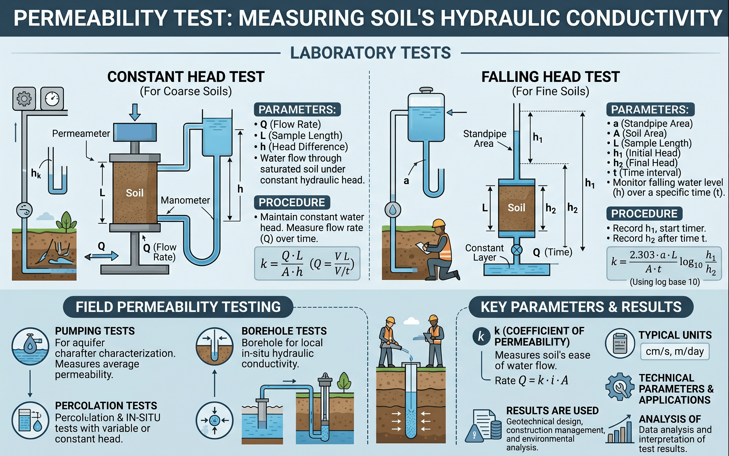
Start by noticing the head difference, specimen length, and flow direction. Those three ideas drive nearly every permeability equation, whether the test uses constant head, falling head, or a field-based method.
What is a permeability test?
A permeability test is a laboratory or field procedure used to estimate how readily water can move through a porous material. In geotechnical engineering, that material is usually soil, but the same concept also applies to rock masses, filter zones, drainage layers, and compacted liner systems. The output is typically hydraulic conductivity, \(k\), sometimes called the coefficient of permeability.
That number matters because groundwater rarely stays “in the background.” It changes effective stress, influences settlement timing, controls whether an excavation can be kept dry, and determines whether seepage through a dam core, embankment, retaining backfill, or pavement layer will be minor or serious. A low \(k\) soil can slow drainage and trap pore pressure. A high \(k\) soil can transmit water rapidly and increase inflow to a cut or trench.
From a design standpoint, permeability testing sits at the intersection of Soil Mechanics, Site Characterization, and groundwater interpretation. On real projects, engineers rarely ask only, “What is the permeability?” The more useful question is, “What permeability value is appropriate for this layer, this flow direction, and this design decision?”
Core principles, variables, and units
Most permeability testing is built around Darcy’s law, which relates discharge to hydraulic gradient, specimen geometry, and hydraulic conductivity. The law works best when flow is laminar, the porous medium is reasonably saturated, and the test setup avoids leakage around the specimen.
In this form, \(Q\) is the discharge rate, \(k\) is hydraulic conductivity, \(i\) is the hydraulic gradient, and \(A\) is the flow area. Since \(i = \Delta h/L\), the test setup is really trying to quantify how a known head difference across a known specimen length produces measurable flow.
Key variables and typical ranges
Hydraulic conductivity varies enormously with soil type and structure. Clean gravels may transmit water very quickly, while intact clays can be many orders of magnitude less permeable. That is why soil classification, specimen disturbance, and flow direction matter so much. A single published “typical” value can be a helpful starting point, but it should never replace project-specific testing and judgment.
- \(k\) Hydraulic conductivity; often reported in m/s or cm/s. Approximate ranges can span from about \(10^{-10}\) m/s for very tight clays to \(10^{-2}\) m/s or higher for coarse gravels.
- \(Q\) Discharge rate; volume per time, such as m³/s or cm³/s. The measured flow must be steady or interpreted correctly for the selected test method.
- \(i\) Hydraulic gradient, equal to head loss divided by specimen length. Large gradients can be convenient for testing, but they should still represent meaningful flow conditions.
- \(A\) Cross-sectional flow area of the specimen. Errors in diameter or cross section directly affect the calculated \(k\).
- \(L\) Specimen length along the flow path. Short specimens can exaggerate the impact of end effects or minor leakage.
- \(\Delta h\) Head difference across the specimen. This is the driving force for seepage and must be measured consistently.
Before trusting a permeability number, ask whether it represents horizontal flow, vertical flow, remolded soil, compacted fill, or intact structure. Those are often very different design values.
Main permeability test methods and when to use them
The best method depends on soil type, expected permeability, sample quality, and the question being answered. Engineers are not just selecting a test; they are selecting the failure mode they most want to avoid in design.
Coarse-grained, relatively free-draining soil usually points toward a constant head test. Finer-grained soil with slower flow usually points toward a falling head test. If in-situ structure, fractures, stratification, or large-scale heterogeneity control performance, a field test may be more meaningful than a lab-only value.
Constant head test
The constant head test is commonly used for sands and gravels where water moves fast enough to maintain a measurable steady discharge under a constant upstream head. Because flow is relatively high, the main advantage is simplicity: once steady conditions are established, you can measure volume over time and compute \(k\) directly. The challenge is that coarse materials are also prone to segregation, side leakage, and specimen disturbance if the setup is sloppy.
Falling head test
The falling head test is typically preferred for silts, fine sands, and other lower-permeability soils where constant-flow measurements become impractical. Here the water level in a standpipe drops with time, and the changing head is used in the calculation. The method is more sensitive for fine soils, but it still depends on good saturation and a representative specimen. Air bubbles, desiccation cracks, or leakage can ruin the result quickly.
Field permeability methods
Field tests become important when the in-situ soil fabric matters more than a trimmed laboratory specimen. Pumping tests, packer tests, infiltration tests, and borehole permeability procedures may capture stratification, fissures, macrovoids, and scale effects that a lab specimen misses. This is especially important in layered alluvium, fissured clay, weathered rock, and embankment materials where flow paths are not uniform.
Equations and calculations
The constant head and falling head tests are both derived from Darcy’s law, but they package the measurements differently. In practice, the math is the easy part; getting a representative, leak-free, saturated specimen is the hard part.
Constant head equation
Here, \(Q\) is the measured volume of water that passes through the specimen during time \(t\), \(L\) is specimen length, \(A\) is cross-sectional area, and \(\Delta h\) is the total head loss across the specimen. This form is useful when discharge is high enough to measure accurately over a short interval.
Falling head equation
In the falling head method, \(a\) is the standpipe cross-sectional area, \(A\) is the specimen cross-sectional area, \(L\) is specimen length, \(t\) is elapsed time, and \(h_1\) and \(h_2\) are the initial and final heads. Because the head changes over time, the logarithmic form captures the decay in driving force.
If your computed permeability for a plastic clay looks like clean gravel, or your coarse sand result looks like intact clay, stop and audit the specimen condition, units, and leakage path before reporting the number.
How engineers run and interpret a permeability test
Good interpretation starts long before the first drop of water moves through the specimen. The workflow usually begins with project context: What layer is being tested? Is the value needed for dewatering, seepage through a compacted barrier, underdrain design, or consolidation timing? That question determines whether intact sampling, remolded preparation, vertical orientation, or horizontal orientation matters.
- Define the design question. Identify whether the test is supporting seepage analysis, drainage design, liner performance, earthwork acceptance, or groundwater control.
- Classify the soil. Use tools such as Sieve Analysis and index testing so the expected permeability range makes sense before the test begins.
- Prepare the specimen carefully. Preserve structure when intact behavior matters, or compact to target density and moisture when engineered fill behavior matters.
- Saturate and seat the specimen. Trapped air can distort the result significantly, especially in finer soils.
- Run the correct method. Match coarse soils to constant head and finer soils to falling head unless a project-specific reason suggests otherwise.
- Check the result against geology and field observations. One laboratory value should be compared with boring logs, stratigraphy, groundwater behavior, and the broader site model.
Engineers then decide whether to report a single value, a range, or directional values. For layered deposits, a range is often more honest than a false sense of precision. A drainage blanket, clay liner, and natural subgrade may all require different interpretations even if each is tested with a “permeability test.”
Worked example
Example: constant head test on a drainage sand
Suppose a cylindrical sand specimen has a length of 0.15 m and a cross-sectional area of 0.00785 m². During a constant head test, 0.0012 m³ of water flows through the specimen in 60 seconds under a head difference of 0.30 m. Using \(k = \frac{Q\,L}{A\,\Delta h\,t}\), the hydraulic conductivity is:
That result is in a believable range for a relatively clean sand. The engineering interpretation is more important than the arithmetic: a value on the order of \(10^{-3}\) m/s suggests the material can function as a drainage layer, transmit seepage quickly, and allow pore pressures to dissipate much faster than a silt or clay would. It also suggests that an excavation in the same deposit could experience noticeable groundwater inflow if the water table is intercepted.
A senior reviewer would still ask follow-up questions: Was the specimen representative of the field deposit? Was the flow direction aligned with expected in-situ seepage? Was the sand uniformly graded or layered with fines? Those questions affect how confidently the value can be used in design.
Engineering judgment and field reality
This is where permeability testing gets interesting. Water does not care about the clean boundaries of a lab specimen. In the field, it follows the weakest or easiest path: fissures in clay, loose seams in fill, sandy partings in silt, joints in rock, poorly compacted lift interfaces, or utility trenches that become preferential drainage paths. A beautifully run lab test can still mislead a project if the specimen does not represent the real flow path.
Direction matters too. Many natural soils are anisotropic, meaning horizontal permeability can differ substantially from vertical permeability because of depositional layering. A vertical lab specimen may be fine for one analysis and misleading for another. The same issue appears in compacted earth structures, where lift interfaces and compaction method can alter directional flow behavior.
If the site contains layering, fissuring, root holes, desiccation cracks, or construction-induced disturbance, a single lab \(k\) value should be treated as one clue, not the whole groundwater model.
This is why permeability results should be folded back into Geotechnical Data Analysis and the site conceptual model. If piezometers, seepage faces, excavation inflow, or pumping response contradict the lab number, the field is telling you something important.
When this breaks down
Permeability testing breaks down when the method assumptions no longer match the actual ground behavior. Darcy-based interpretation becomes less reliable if flow is not laminar, if the specimen is not saturated, or if the sample has been disturbed enough to change its structure significantly. In fissured clay, highly variable fill, or fractured rock, a small specimen may completely miss the dominant field flow paths.
Another limitation appears when engineers want one number to serve too many roles. The permeability relevant to seepage through a compacted clay core is not automatically the right number for a temporary excavation inflow estimate. Likewise, the permeability controlling consolidation timing may be a vertical drainage value, while lateral seepage around a cutoff wall depends more on horizontal pathways.
Temperature, chemistry, degree of saturation, and fine-particle migration can also change behavior. Filters and transition zones that look acceptable at first can clog or reorganize under flow. Fine-grained soils can crack during drying. Remolded specimens can understate the effect of natural structure. Those are not minor details; they are often the reasons a design underperforms.
Common pitfalls and engineering checks
- Using a constant head setup on a soil that drains too slowly to produce reliable steady-flow measurements.
- Reporting a permeability value without stating whether the specimen was intact, remolded, or compacted to a target density and moisture.
- Ignoring anisotropy and assuming one measured value is valid for every seepage direction.
- Failing to saturate the specimen fully or overlooking trapped air in fine soils.
- Missing sidewall leakage, end leakage, or piping through a disturbed specimen edge.
- Using the result without comparing it to soil classification, groundwater observations, and the broader site model.
One of the most expensive mistakes is using an unrealistically low or high \(k\) value in dewatering or seepage analysis, then discovering in construction that groundwater inflow or underdrain performance behaves nothing like the model.
| Design question | What permeability controls | Preferred interpretation | Engineering check |
|---|---|---|---|
| Excavation dewatering | Rate of groundwater inflow | Field-scale or stratified value range | Compare against observed water table and pumping response |
| Clay liner or cutoff wall | Seepage resistance | Compacted/remolded low-permeability result | Check moisture-density control and construction defects |
| Drainage blanket or filter layer | Water transmission capacity | Higher-permeability coarse-grained value | Verify gradation compatibility and clogging risk |
| Settlement timing | Pore-pressure dissipation rate | Often vertical drainage-relevant value | Cross-check with consolidation testing and drainage path length |
Relevant standards and design references
Permeability results should be tied to recognized procedures and then interpreted in the context of project-specific geology and design objectives. The exact standard used may vary by agency and material type, but these are the references engineers commonly look for.
- ASTM D2434: Standard laboratory test method for permeability of granular soils using a constant head. Commonly applied to sands and gravels where steady flow can be measured.
- ASTM D5084: Laboratory hydraulic conductivity testing of saturated porous materials using flexible wall permeameters. Important for low-permeability soils and compacted barrier materials where side leakage control matters.
- ASTM D5856: Measurement of hydraulic conductivity of saturated porous materials using a rigid-wall, compaction-mold permeameter. Often relevant for compacted soils in earthwork and liner-related work.
- AASHTO and agency earthwork specifications: Project owners may supplement ASTM methods with acceptance criteria for liners, drains, roadway layers, and embankment materials.
- USACE, USBR, and dam or levee guidance: Frequently used where seepage control, filter compatibility, underseepage, and erosion resistance are major design drivers.
Frequently asked questions
It measures hydraulic conductivity, which tells you how easily water can pass through a soil or other porous material under a hydraulic gradient. In geotechnical work, that number is used to judge seepage, drainage, dewatering feasibility, and how quickly pore pressures may dissipate.
Constant head is generally better for coarse soils with high flow rates because steady discharge can be measured directly, while falling head is better for finer soils where flow is too slow for a practical constant-head setup. The choice depends on soil type, expected permeability range, and measurement sensitivity.
Usually not. Sites often contain layered soils, variable gradation, fissures, fill interfaces, and changing groundwater conditions, so engineers commonly work with ranges or different values for different strata and flow directions rather than one universal number.
Lab specimens are smaller, more controlled, and often cleaner than field conditions, so they may miss fractures, macrovoids, stratification, disturbance, or construction defects that dominate actual seepage. That is why permeability testing should be interpreted together with logs, groundwater observations, and field performance.
It appears in dewatering studies, excavation support, dam and levee seepage checks, drainage layer design, landfill and pond liner work, pavement drainage, retaining wall backdrain evaluation, and settlement analyses where pore-pressure dissipation rate matters.
Summary and next steps
A permeability test is one of the clearest ways to connect soil behavior to groundwater-driven design decisions. It turns a qualitative idea, “this soil drains fast” or “this layer is tight,” into a number that can support seepage estimates, drainage details, dewatering strategy, and settlement timing.
The most important engineering lesson is that permeability is not just a material property in the abstract. It depends on soil type, structure, anisotropy, specimen condition, and scale. Good geotechnical practice means matching the test method to the material, then matching the result to the actual design question.
When in doubt, treat permeability data as part of a larger site model rather than a stand-alone answer. If the value lines up with classification, groundwater observations, and field performance, it becomes much more useful and defensible.
Where to go next
Continue your learning path with these closely related geotechnical topics.
-
Read a deeper dive on Soil Mechanics
Build the theory behind seepage, effective stress, drainage, and the soil behavior that permeability results feed into.
-
Study Site Characterization
See how permeability results fit into the bigger subsurface model instead of being treated as an isolated lab number.
-
Review Soil Consolidation
Follow the link between permeability, pore-pressure dissipation, and the timing of settlement in fine-grained soils.