Key Takeaways
- Core idea: A generator converts mechanical rotation into electrical output by using electromagnetic induction.
- Engineering use: In power systems, generators supply real power, support voltage, interact with protection systems, and connect through switchgear and transformers.
- What controls it: The governor controls prime mover input and real power, while excitation and the AVR control voltage and reactive power behavior.
- Practical check: Nameplate ratings, cooling, grounding, synchronization, protection, and operating limits matter as much as the basic generator principle.
Table of Contents
Introduction
Generators are electric power-system machines that convert mechanical energy into electrical energy, most often by rotating a magnetic field relative to stationary windings. In engineering practice, a generator is not just a spinning machine; it is part of a controlled system that includes a prime mover, excitation system, governor, breaker, transformer, protection relays, and grid or load connection.
Generator System Overview
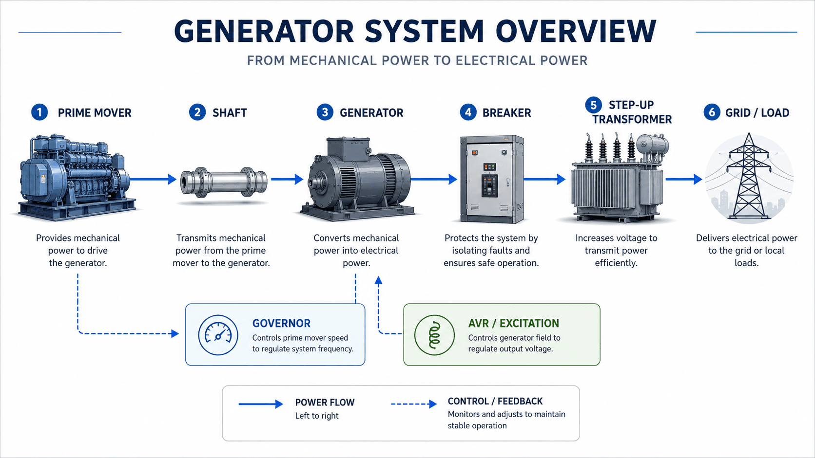
Read the diagram from left to right first: the prime mover supplies mechanical power, the shaft transfers torque, the generator converts energy, the breaker isolates faults, the transformer raises voltage, and the grid or local load receives electrical power.
What Is an Electric Generator?
An electric generator is an electromechanical energy conversion device. It accepts mechanical power at a rotating shaft and produces electrical power at its terminals. In most utility and industrial power systems, the machine is an AC generator, often a synchronous generator, because it can produce voltage at a controlled frequency and support grid operation.
The simplest explanation is “mechanical energy becomes electrical energy,” but that definition is incomplete for power systems engineering. A real generator must be controlled, cooled, protected, grounded, synchronized, and operated within rating limits. Its behavior affects voltage regulation, frequency stability, short-circuit current, reactive power flow, and the reliability of connected loads.
On this page, “generator” means an electric generator used in a power-system context. Portable engine-generator sets, standby generators, hydro generators, steam turbine generators, and utility-scale synchronous generators all use the same basic energy-conversion idea, but their controls, ratings, protection, and grid behavior can be very different.
How Generators Produce Voltage
Most generators operate by electromagnetic induction. A magnetic field moves relative to a set of conductors, causing voltage to be induced in the windings. In a common AC generator, the rotor spins and establishes a rotating magnetic field, while the stator contains the stationary output windings connected to the load or grid.
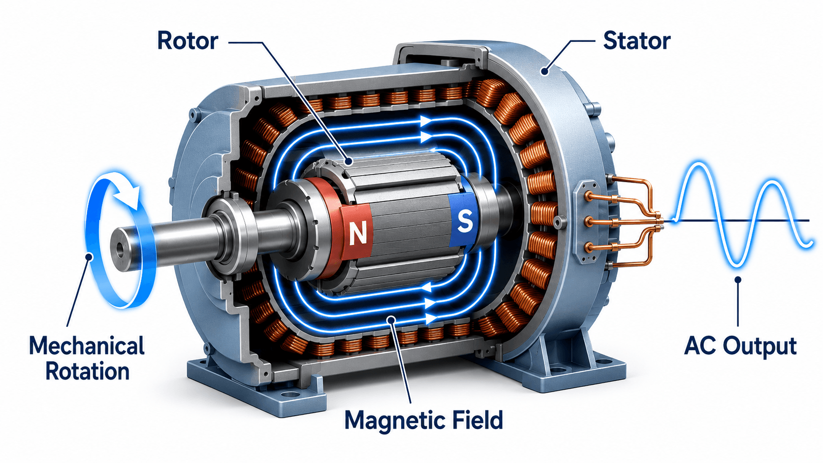
Rotor and stator roles
The rotor is the rotating part of the generator. In many synchronous generators, it carries the field system that creates magnetic flux. The stator is the stationary outer portion that contains the armature windings where output voltage is induced. This separation allows high-power output conductors to remain stationary, which is practical for insulation, cooling, and terminal connections.
Magnetic flux and induced voltage
The induced voltage depends on how quickly magnetic flux changes through the stator windings. A useful way to describe the principle is Faraday’s law:
In this expression, \(e\) is induced voltage, \(N\) is the number of winding turns, and \(\frac{d\Phi}{dt}\) is the rate of change of magnetic flux. The negative sign represents Lenz’s law, which means the induced voltage opposes the change that created it.
Why generator speed matters
For a synchronous AC generator, electrical frequency is tied to rotor speed and the number of magnetic poles. The common relationship is:
where \(f\) is frequency in hertz, \(P\) is the number of poles, and \(n\) is mechanical speed in revolutions per minute. This is why speed control is essential for stand-alone generators and why synchronized grid-connected generators must operate in step with the power system.
The simplified N-S rotor diagram is useful for learning, but actual generator rotors may be salient-pole machines, common in many hydro generators, or cylindrical rotors, common in high-speed steam and gas turbine generators.
Generator Terms That Are Often Confused
The word generator is broad, so searchers often mix together electric generators, alternators, standby generator sets, inverter generators, and inverter-based resources. The table below separates the most common terms.
| Term | What it usually means | Where it fits in power systems |
|---|---|---|
| Generator | A broad term for equipment that converts mechanical input into electrical output. | Used for utility generators, standby generators, industrial generators, and many rotating electrical sources. |
| Alternator | An AC generator, often used in vehicle, industrial, and rotating-machine language. | Technically a type of generator because it produces alternating current. |
| Synchronous generator | An AC generator whose rotor speed is locked to system frequency. | Common in large power plants and important for voltage control, inertia, and grid support. |
| Standby generator | An engine-generator set used for backup power during utility outages. | Important for facilities, data centers, hospitals, industrial sites, and emergency systems. |
| Inverter generator | A generator set that uses power electronics to condition the output. | Common in smaller portable units where cleaner voltage and variable-speed operation are useful. |
| Inverter-based resource | A source such as solar PV, battery storage, or some wind systems connected through power electronics. | Does not behave like a traditional rotating synchronous generator unless controls are designed to provide grid-support functions. |
Common Types of Generators in Power Systems
The correct generator type depends on the energy source, operating speed, grid connection, voltage requirements, control strategy, and protection philosophy. A generator used in a hydro plant does not behave exactly like a diesel standby generator or an inverter-connected renewable resource.
| Generator type | How it is commonly used | Power-system implication |
|---|---|---|
| Synchronous generator | Large thermal, hydro, nuclear, and many industrial power plants. | Can regulate voltage through excitation and contributes short-circuit current and rotational inertia. |
| Induction generator | Some wind and small hydro applications, especially older or simpler systems. | Usually depends on the grid or capacitors for magnetizing reactive power and behaves differently from a synchronous machine during faults. |
| DC generator | Specialized or legacy applications, battery charging, excitation systems, and educational examples. | Produces direct-current output but is less common for modern bulk power generation. |
| Engine-generator set | Diesel, natural gas, or other engine-driven backup and distributed generation systems. | The generator rating must be checked with starting current, load step, duty rating, cooling, fuel supply, and voltage dip requirements. |
| Inverter-based generation | Solar PV, battery energy storage, many modern wind turbines, and power electronics interfaces. | Fault current, inertia, voltage support, and frequency response depend heavily on inverter controls rather than rotating mass alone. |
In power plant discussions, “generator” often means a large synchronous generator. In residential or portable equipment discussions, “generator” may mean the entire engine-generator set, including fuel system, controls, enclosure, alternator, and breaker.
Generator Ratings: kW, kVA, Voltage, Frequency, and Power Factor
Generator ratings describe both the electrical output and the operating limits of the machine. A nameplate rating is not just a marketing number; it reflects thermal capacity, insulation limits, cooling, voltage class, winding current, power factor capability, and acceptable operating conditions.
| Rating or quantity | What it means | Engineering implication |
|---|---|---|
| kW | Real power delivered to loads or the grid. | Primarily controlled by mechanical input from the prime mover and limited by fuel, turbine output, engine capacity, and thermal rating. |
| kVA | Apparent power based on voltage and current. | Important for winding current and thermal loading; a generator can hit its kVA limit before reaching its maximum possible kW at low power factor. |
| kVAR | Reactive power exchanged with the power system. | Closely tied to excitation, voltage support, and generator capability curve limits. |
| Voltage | Generator terminal voltage, often stepped up for transmission. | Must match equipment insulation class, transformer ratio, switchgear rating, and system voltage-control requirements. |
| Frequency | AC cycles per second, typically 50 Hz or 60 Hz depending on system region. | In islanded operation, frequency follows generator speed; in grid-connected operation, the grid largely establishes frequency. |
| Power factor | Relationship between real power and apparent power. | Affects how much real power can be delivered without exceeding stator current or reactive capability limits. |
The common three-phase relationships are:
Here, \(S\) is apparent power, \(V_{LL}\) is line-to-line voltage, \(I\) is line current, \(P\) is real power, and PF is power factor. These relationships are why generator ratings often include both kVA and kW. For more support with this relationship, use the Power Factor Calculator.
If a generator is rated 1,000 kVA at 0.8 power factor, its rated real power is typically 800 kW. Loading it to 1,000 kW would exceed the intended real-power rating even though the kVA number looks larger.
Generator Capability Limits
A generator nameplate does not describe every possible operating limit. Large synchronous generators are often evaluated using a capability curve, which shows the acceptable combinations of real power and reactive power. This matters because a generator may be connected and spinning but still limited by heating, excitation, stator current, or stability constraints.
| Capability limit | What controls it | Why it matters |
|---|---|---|
| Prime mover limit | Fuel input, steam flow, water flow, turbine output, or engine mechanical capacity. | Limits sustained real power even if the electrical machine could carry more current. |
| Stator current limit | Armature winding current and stator thermal capacity. | Can limit kVA output before the generator reaches maximum kW. |
| Rotor field heating | Excitation current and rotor thermal capacity. | Limits overexcited operation and reactive power support. |
| Underexcitation limit | Low field current, end-region heating, and stability margin. | Restricts operation when the generator absorbs reactive power or operates near stability boundaries. |
| Cooling limit | Air, hydrogen, water, oil, ambient temperature, and cooling system performance. | Actual continuous output can be reduced when cooling conditions are worse than rating assumptions. |
This is why generator studies and operating procedures often look beyond a single kW value. The safe operating point depends on real power, reactive power, voltage, current, cooling, excitation, and system conditions at the same time.
Generator Control: Governor, Excitation, Voltage, and Frequency
Generator control is easier to understand when the two main control paths are separated. The governor changes mechanical input to the prime mover, while the excitation system changes the magnetic field of the generator. Together, these systems determine how the generator shares load, supports voltage, and remains stable.
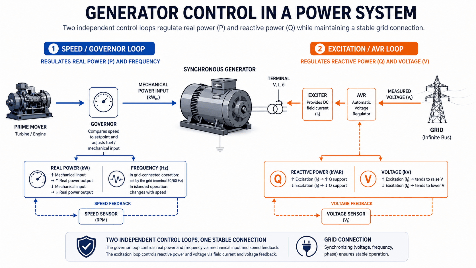
Governor and real power
The governor controls the prime mover input. In a turbine-generator set, that may mean changing steam valves, water gates, fuel flow, or combustion controls. Increasing mechanical input generally increases real power output when connected to a grid. In a strong grid, governor action changes the unit’s real-power output and contributes to system frequency response, but system frequency is determined by the balance of all generation and load.
Excitation and reactive power
The excitation system supplies field current to the rotor of a synchronous generator. The automatic voltage regulator, or AVR, adjusts that field current to maintain terminal voltage or reactive power behavior. More excitation generally increases reactive power support and tends to raise voltage, while less excitation reduces reactive support and tends to lower voltage. Leading and lagging terminology should always be interpreted using the project’s generator sign convention.
Grid-connected versus islanded behavior
A grid-connected generator is electrically tied to a much larger system. The grid strongly influences frequency and voltage, while the generator contributes real and reactive power according to its controls and limits. A stand-alone generator has no large grid to lean on, so load changes can cause larger voltage and frequency swings unless the governor and AVR respond properly.
Where Generators Are Used in Power Systems
Generators appear in many parts of the electrical system, from utility-scale plants to facility backup power. The basic conversion principle is similar, but the engineering priorities change depending on the source, duty cycle, voltage level, and connection point.
| Application | Typical generator context | Key engineering concern |
|---|---|---|
| Steam turbine generation | Large thermal, nuclear, biomass, or combined-cycle plants. | High-speed synchronous generator operation, cooling, excitation, protection, and step-up transformer connection. |
| Gas turbine generation | Simple-cycle and combined-cycle plants used for capacity, peaking, and grid support. | Fast start capability, load ramping, governor response, and generator thermal limits. |
| Hydro generation | Water turbine drives a generator, often at lower mechanical speed. | Salient-pole machines, water flow control, inertia, excitation, and grid synchronization. |
| Diesel or natural gas standby generation | Backup power for facilities, critical loads, microgrids, and emergency systems. | Load step response, motor starting, fuel supply, voltage dip, duty rating, and transfer scheme. |
| Wind turbine generation | Modern systems often use power electronics between the generator and grid. | Inverter controls, reactive support, fault ride-through, and grid-code requirements. |
| Industrial cogeneration | Combined heat and power systems serving plant loads and sometimes exporting power. | Parallel operation, protection coordination, heat recovery, load sharing, and interconnection rules. |
| Microgrids and stand-alone systems | Generators operate with other distributed resources or as the primary source. | Frequency control, voltage regulation, load sharing, black start, and coordination with inverters or batteries. |
For broader context on generation sources and system-level energy conversion, review Power Generation.
Connecting a Generator to the Grid
A generator cannot simply be switched onto an energized grid at any random moment. Before closing the breaker, the generator voltage must be synchronized with the system. Poor synchronization can create severe mechanical torque, high current, breaker stress, shaft stress, and voltage disturbance.
| Synchronization check | What must be reviewed | Why it matters |
|---|---|---|
| Voltage magnitude | Generator terminal voltage compared with bus voltage. | Large mismatch can create reactive current and voltage disturbance when the breaker closes. |
| Frequency | Generator frequency compared with grid frequency. | Frequency mismatch means the generator is not rotating at the correct synchronous speed relative to the grid. |
| Phase sequence | Correct A-B-C phase rotation. | Wrong phase sequence can cause severe electrical and mechanical problems when paralleled. |
| Phase angle | Angular difference between generator voltage and grid voltage. | Large phase-angle error can create high synchronizing current and torque shock. |
| Breaker and protection status | Breaker readiness, relay permissives, trip circuits, and synchronization logic. | Controls and protection must be ready before the generator is placed in service. |
In modern systems, synchronizing equipment and relay logic may automate much of this process, but the engineering checks remain the same: the generator and grid must be electrically compatible before they are paralleled.
Generator Protection Basics
Generator protection is designed to detect abnormal conditions and isolate the machine before damage spreads. Generators are expensive, mechanically complex, and strongly connected to the rest of the power system, so protection schemes must address both electrical faults and machine operating problems.
| Protection concern | What it detects | Why it matters for generators |
|---|---|---|
| Differential protection | Mismatch between current entering and leaving the protected generator zone. | Provides fast detection of internal winding or terminal faults. |
| Ground fault protection | Fault current involving the generator neutral, stator winding, or grounding system. | Grounding method strongly affects fault magnitude and relay sensitivity. |
| Reverse power | Power flowing into the generator instead of out of it. | Can indicate loss of prime mover input, causing the generator to motor the turbine or engine. |
| Loss of excitation | Weak or failed field current in a synchronous generator. | Can cause reactive power issues, overheating, instability, and abnormal machine behavior. |
| Over/under voltage and frequency | Terminal voltage or frequency outside acceptable operating range. | Protects the machine and connected loads from abnormal operating conditions. |
| Thermal protection | Excessive winding, bearing, coolant, or machine temperature. | Generator output is often limited by heat removal, not only by electrical theory. |
| Short-circuit behavior | Subtransient, transient, and sustained fault-current response. | Generator fault current is not constant, so protection studies must account for time-varying machine behavior. |
For a deeper relay-focused explanation, review Differential Protection and Protective Relays as related power-system protection topics.
Generators, Inertia, and Inverter-Based Resources
Traditional synchronous generators provide rotating inertia because their rotor mass is physically spinning in synchronism with the grid. That inertia helps resist sudden frequency changes after disturbances. It also contributes fault current and voltage behavior that protection systems and stability studies have historically relied on.
Inverter-based resources, such as solar PV and battery energy storage, connect through power electronics rather than directly through a large spinning synchronous machine. They can still support the grid, but their behavior depends on inverter controls, current limits, ride-through settings, and grid-forming or grid-following control strategy. This is why a solar or battery resource should not be modeled as a traditional generator unless the study assumptions support it.
When reviewing a generation resource, confirm whether it is a rotating synchronous generator, an induction generator, or an inverter-based resource. Fault current, voltage support, inertia, protection response, and stability behavior may be very different.
Practical Generator Sanity-Check Table
A generator review should connect the physical machine, the prime mover, the electrical output, and the operating environment. The table below is a practical checklist for understanding whether a generator is being described, modeled, sized, or operated correctly.
Start with the nameplate and connected system, confirm the prime mover and control mode, review kW/kVA/power factor limits, then verify protection, grounding, synchronization, cooling, and operating restrictions before treating the generator as available capacity.
| Generator check | What to look for | Why it matters |
|---|---|---|
| Nameplate kW and kVA | Rated apparent power, real power, voltage, phase, frequency, and power factor. | Prevents confusing electrical capacity with usable real-power output. |
| Prime mover limit | Turbine, engine, water flow, steam flow, fuel supply, or mechanical drive capability. | The generator cannot deliver more sustained real power than the mechanical source can provide. |
| Load and starting current | Motor starting, transformer energization, nonlinear loads, step loads, and voltage-dip tolerance. | Generator sizing is not only a steady-state kW problem; transient response can control the correct selection. |
| Cooling method | Air, hydrogen, water, oil, ventilation, ambient temperature, and cooling alarms. | Thermal limits often define continuous rating and overload capability. |
| Excitation and AVR mode | Voltage setpoint, reactive power control mode, field current, and limiter status. | Controls voltage support and reactive power behavior while protecting machine limits. |
| Governor response | Droop setting, speed setpoint, load-sharing behavior, and fuel or valve response. | Determines real-power response and frequency behavior, especially in islanded systems. |
| Synchronization readiness | Voltage, frequency, phase sequence, phase angle, breaker permissives, and synchronizer status. | Improper paralleling can damage equipment and disturb the system. |
| Protection and grounding | Relay functions, CT/VT inputs, neutral grounding, trip circuits, and alarm logic. | Fault behavior and protection sensitivity depend on the machine and system configuration. |
| Operating limits | Capability curve, underexcitation limit, overexcitation limit, stator current limit, and stability margin. | A generator may be electrically connected but still limited by reactive capability or thermal constraints. |
Engineering Judgment and Field Reality
Textbook diagrams often show a generator as a simple rotating magnet and coil. Real generators are more demanding. Winding insulation ages, cooling systems degrade, protective relays depend on correct instrument transformer data, governors can respond slowly, and excitation limiters can restrict output before an operator expects it.
Engineers also need to distinguish between grid-connected and islanded assumptions. A generator connected to a strong grid behaves differently from the same generator serving a small isolated load. In a weak or islanded system, a motor starting event, sudden load rejection, or poor AVR response can create voltage and frequency swings that would be barely noticeable on a strong utility grid.
A generator that looks large enough by kW alone may still be a poor fit if its short-circuit contribution, voltage recovery, cooling margin, neutral grounding, or reactive capability does not match the connected system.
When This Breaks Down
The simplified idea that a generator “makes electricity by spinning” is useful, but it breaks down when the machine is connected to real loads, protection systems, and grid operating constraints. At that point, generator behavior depends on controls, limits, system strength, fault conditions, and operating mode.
- Weak grid or islanded operation: Voltage and frequency may move significantly with load changes because there is no large grid to absorb disturbances.
- Low power factor loading: The generator can reach stator current or reactive capability limits before its kW rating is fully used.
- Fault conditions: Generator fault current changes through subtransient, transient, and steady-state periods, so short-circuit contribution is not a single fixed value.
- Thermal limits: Ambient conditions, cooling system performance, winding temperature, and overload duration can limit output.
- Control interactions: AVR, governor, limiters, stabilizers, and protection settings can interact during disturbances in ways a simple block diagram does not show.
- Inverter-based sources: Solar, battery, and many modern wind resources may not provide the same inertia, fault current, or voltage response as a rotating synchronous generator.
Common Generator Mistakes and Practical Checks
Many generator misunderstandings come from treating the machine as a black box. For power systems work, it is more useful to think in terms of energy conversion, ratings, control loops, protection zones, and the electrical strength of the connected system.
- Using kVA as if it were kW: Apparent power and real power are related, but they are not the same. Power factor matters.
- Ignoring reactive power capability: Voltage support can be limited by excitation, stator current, rotor heating, and stability limits.
- Assuming frequency control is the same in every mode: A generator connected to a strong grid does not set system frequency by itself; an islanded generator has much more direct frequency responsibility.
- Skipping synchronization details: Closing a generator breaker without matching voltage, frequency, phase sequence, and phase angle can create severe equipment stress.
- Underestimating protection coordination: Generator relays must coordinate with machine limits, grounding method, transformer connection, switchgear, and system protection.
- Calling every source a generator in studies: A synchronous generator, induction generator, and inverter-based resource can require different assumptions for load flow, short circuit, protection, and stability analysis.
Do not size or evaluate a generator using only the connected load kW. Starting current, power factor, voltage dip, motor loads, harmonic content, standby rating, ambient conditions, and allowable frequency deviation can all change the correct selection.
Useful References and Design Context
Generator design and application depend on the machine type, project requirements, protection philosophy, interconnection rules, operating mode, and owner standards. A public reference is useful for understanding the basic energy conversion path before moving into project-specific generator specifications.
- U.S. Energy Information Administration: EIA explanation of how electricity is generated describes how turbine-generator sets convert mechanical energy into electrical energy for electric power production.
- Project-specific criteria: Utility interconnection requirements, facility standards, generator manufacturer data, relay settings, grounding design, and local electrical codes can control the final engineering application.
- Engineering use: Engineers use generator references alongside equipment nameplates, system studies, load data, protection settings, and commissioning records to confirm the machine can operate safely in its intended system.
Frequently Asked Questions
A generator is the source machine that converts mechanical power into electrical power for loads or the grid. In a power system, it is normally connected with a prime mover, excitation system, governor, breaker, transformer, protection relays, and control equipment so the output can be delivered safely and reliably.
A generator produces electricity by moving a magnetic field relative to conductors. In most AC generators, a rotor creates a rotating magnetic field and the stator windings experience changing magnetic flux, which induces voltage at the generator terminals.
An alternator is a type of AC generator. In everyday language the terms are sometimes used interchangeably, but generator is the broader term because it can include AC generators, DC generators, synchronous generators, standby generator sets, and other electrical sources.
kW is real power that performs useful work, while kVA is apparent power based on voltage and current. The relationship depends on power factor, so a generator with a high kVA rating may not be able to deliver the same numeric value in kW unless the power factor supports it.
A generator and a motor are closely related electromechanical machines, but they convert energy in opposite directions. A generator converts mechanical input into electrical output, while a motor converts electrical input into mechanical output.
Before paralleling a generator with an energized grid, the voltage magnitude, frequency, phase sequence, and phase angle must be matched closely. Protection, breaker status, grounding, controls, and synchronization logic should also be verified before closing the generator breaker.
Summary and Next Steps
Generators convert mechanical power into electrical power, but their power-system role is much broader than the basic conversion principle. A useful generator explanation must include the rotor, stator, prime mover, excitation, governor, ratings, capability limits, protection, transformer connection, and grid or load interface.
In practice, engineers review kW, kVA, power factor, voltage, frequency, cooling, grounding, synchronization, and protection before assuming a generator can support a load or grid connection. The most important split is that mechanical input primarily drives real power, while excitation primarily affects voltage and reactive power behavior.
Where to go next
Continue your learning path with related Turn2Engineering resources.
-
Power Generation
See how generators fit into the larger process of converting energy sources into grid-ready electrical power.
-
Load Flow Analysis
Learn how generator real and reactive power output is represented in steady-state power-system studies.
-
Differential Protection
Explore one of the most important protection methods used for generators, transformers, buses, and other major equipment.