Key Takeaways
- Core idea: A heat engine converts part of an input heat flow into useful work while rejecting the remaining heat to a lower-temperature sink.
- Engineering use: Engineers use heat engine analysis to evaluate steam turbines, gas turbines, internal combustion engines, power plants, and propulsion systems.
- What controls it: Efficiency depends on hot-side temperature, cold-side temperature, cycle design, heat transfer quality, pressure losses, and irreversibilities.
- Practical check: Carnot efficiency is only an upper limit; real engines always perform below it because of friction, finite heat transfer, leakage, exhaust losses, and material limits.
Table of Contents
Introduction
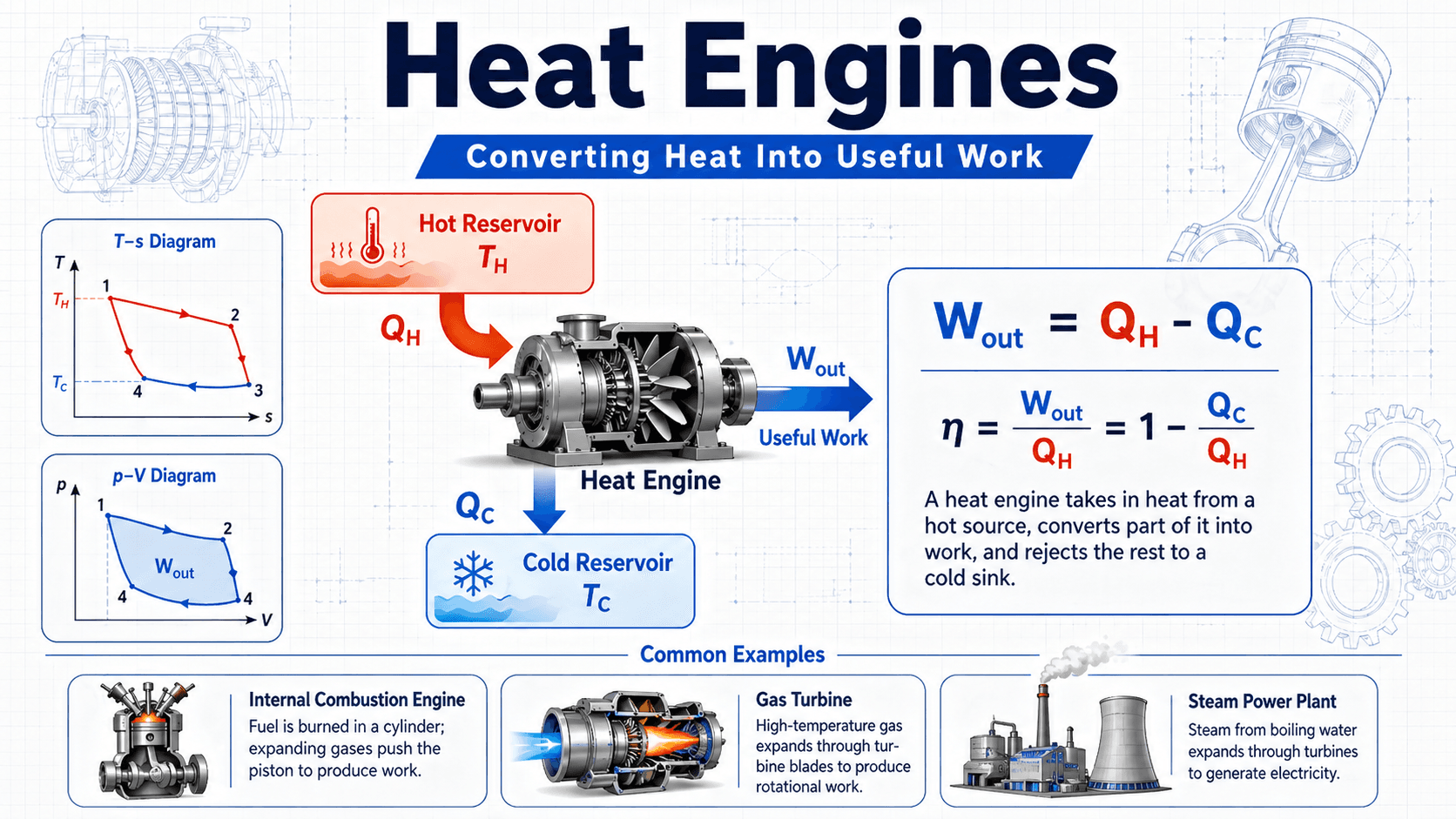
Heat engines are thermodynamic devices that convert heat into useful work by operating between a hot reservoir and a cold reservoir. They absorb heat from a high-temperature source, produce mechanical or shaft work, and reject unused heat to a lower-temperature sink. This simple idea explains car engines, steam turbines, gas turbines, and many power generation systems.
How Heat Engines Work
Notice that the engine does not turn all incoming heat into work. The rejected heat is not a minor detail; it is part of what makes a cyclic heat engine possible and is the reason thermal efficiency is always less than 100 percent.
What is a Heat Engine?
A heat engine is a system that repeatedly goes through a thermodynamic cycle to convert thermal energy into useful work. The working fluid may be combustion gas, steam, air, refrigerant, or another fluid depending on the engine type. During the cycle, the system receives heat, expands or otherwise produces work, rejects heat, and returns to its starting state.
In mechanical engineering, heat engines are not just textbook diagrams. They are the foundation behind steam power plants, gasoline engines, diesel engines, aircraft turbines, combined-cycle plants, and many industrial power systems. The key engineering question is not simply whether heat can become work, but how much work can be extracted reliably, safely, and economically from a given temperature difference.
The Basic Heat Engine Cycle
Every heat engine needs three basic roles: a high-temperature energy source, a working device or fluid that produces work, and a lower-temperature sink that receives rejected heat. The engine repeats this process so that it can deliver continuous or repeated work output rather than a single one-time expansion.
Hot Reservoir, Heat Input, and Expansion
The hot reservoir supplies heat, often labeled \(Q_H\). In a gasoline engine, this heat comes from combustion inside the cylinder. In a steam power plant, fuel or another heat source produces steam that expands through a turbine. In an idealized cycle, this heat input raises the energy of the working fluid so it can expand and push a piston, spin a turbine, or generate shaft power.
Work Output and Heat Rejection
The useful work output, often labeled \(W_{out}\), is the part of the incoming energy that becomes mechanical output. The remaining energy is rejected as \(Q_C\) to a cold sink, such as the atmosphere, cooling water, exhaust stream, radiator, condenser, or surrounding environment. A practical engine must manage both sides: extracting useful work and removing waste heat without overheating equipment.
Where Heat Engines Are Used in Mechanical Engineering
Heat engines appear anywhere engineers need to convert thermal energy, chemical energy, or fuel energy into motion, electricity, or propulsion. The same thermodynamic principles apply across many machines, even when the hardware looks completely different.
- Power plants: Steam turbines and gas turbines convert heat into shaft work that drives generators.
- Transportation: Gasoline engines, diesel engines, jet engines, and marine engines convert fuel energy into propulsion.
- Industrial systems: Turbines, engines, and waste-heat recovery systems support pumps, compressors, generators, and mechanical drives.
When comparing heat engines, do not compare efficiency alone. Also check power output, operating temperature, duty cycle, fuel type, emissions, cooling requirements, maintenance burden, startup time, and how much rejected heat can be recovered or reused.
What Controls Heat Engine Performance?
A heat engine is controlled by more than its fuel source. Efficiency and power output depend on temperature limits, pressure ratios, working fluid behavior, heat transfer rates, component losses, and how closely the actual cycle follows the ideal cycle used in analysis.
| Factor | Why it matters | Engineering implication |
|---|---|---|
| Hot-side temperature | A higher source temperature increases the theoretical opportunity to convert heat into work. | Engineers often seek higher combustion, steam, or turbine inlet temperatures, but materials and cooling limits become critical. |
| Cold-side temperature | A lower sink temperature improves the theoretical efficiency limit. | Condensers, radiators, cooling towers, and ambient conditions can strongly affect real performance. |
| Irreversibility | Friction, turbulence, pressure drops, heat leakage, and non-ideal combustion destroy useful work potential. | Reducing losses often requires better component design, tighter tolerances, improved heat exchangers, and better controls. |
| Cycle type | Different cycles add and reject heat in different ways. | Otto, Diesel, Brayton, Rankine, Stirling, and combined cycles are selected for different fuels, scales, and operating goals. |
| Operating load | Engines rarely operate at their ideal design point all the time. | Part-load operation, transient duty, startup losses, and cycling can reduce real-world efficiency below rated values. |
Heat Engine Efficiency Equations
The most common heat engine calculation compares useful work output to heat input. For a complete cycle, the net work output equals heat received from the hot reservoir minus heat rejected to the cold reservoir.
This equation shows why reducing rejected heat or increasing useful work improves efficiency, but it does not mean rejected heat can be reduced to zero. A cyclic heat engine must reject heat to operate between two reservoirs.
- \(Q_H\) Heat absorbed from the hot reservoir, usually in joules, kilojoules, Btu, or kJ/kg for specific cycle analysis.
- \(Q_C\) Heat rejected to the cold reservoir, condenser, exhaust, radiator, cooling water, or surrounding environment.
- \(W_{out}\) Useful net work output from the cycle, often measured as shaft work, brake work, turbine work, or specific work.
- \(\eta\) Thermal efficiency, usually reported as a decimal or percentage.
Carnot Efficiency
The Carnot efficiency gives the maximum possible efficiency for any heat engine operating between a hot reservoir and a cold reservoir. It is an upper bound, not a prediction of real engine performance.
The reservoir temperatures \(T_H\) and \(T_C\) must be absolute temperatures, normally Kelvin. Using Celsius or Fahrenheit in this equation is one of the most common heat engine calculation errors.
Types of Heat Engines
Heat engines can be grouped by where combustion occurs, what working fluid is used, and which thermodynamic cycle best represents the process. The ideal cycle is a model; the real machine includes losses, controls, hardware limits, and operating constraints.
| Engine or cycle | Common example | Useful engineering idea |
|---|---|---|
| Otto cycle | Spark-ignition gasoline engine | Useful for understanding compression ratio, combustion timing, and piston engine efficiency. |
| Diesel cycle | Compression-ignition diesel engine | Important for heavy vehicles, generators, marine engines, and high-torque applications. |
| Brayton cycle | Gas turbine or jet engine | Used for propulsion, power generation, and combined-cycle power plants. |
| Rankine cycle | Steam turbine power plant | Central to steam power generation, boilers, condensers, pumps, and turbine analysis. |
| Stirling cycle | External combustion engine | Useful for understanding external heat addition, regeneration, and temperature-difference engines. |
| Carnot cycle | Ideal reference engine | Defines the theoretical efficiency limit between two reservoirs. |
PV Diagrams and Work Output
A pressure-volume diagram helps show how a heat engine produces net work over a cycle. For a closed loop on a PV diagram, the area inside the loop represents net work. A clockwise loop typically represents a heat engine because the system produces positive net work over the cycle.
Why the Loop Matters
A single expansion process may produce work once, but a useful engine must repeat. That is why cycle analysis matters. The system must return to its initial state so the process can continue, which means heat input, work output, heat rejection, and compression or reset processes all matter.
What a PV Diagram Does Not Show by Itself
A PV diagram can show pressure-volume work, but it does not automatically show all real losses. Friction, heat leakage, incomplete combustion, pump work, compressor work, turbulence, valve losses, and mechanical efficiency must be considered separately in real machine analysis.
Heat Engine Analysis Checklist
Use this checklist when reviewing a heat engine problem, comparing engine types, or interpreting an efficiency value. It helps separate ideal thermodynamics from practical engine behavior.
Start with the energy flows: identify \(Q_H\), \(Q_C\), and \(W_{out}\). Then confirm the cycle type, reservoir temperatures, working fluid, units, and whether the result is ideal, indicated, brake, net, or overall system efficiency. Finally, compare the result against the Carnot limit and look for real losses that explain the gap.
| Check or decision | What to look for | Why it matters |
|---|---|---|
| Define the system boundary | Engine only, turbine only, full plant, vehicle powertrain, or combined-cycle system. | Efficiency changes depending on what losses are included inside the boundary. |
| Confirm the heat reservoirs | Hot source temperature, cold sink temperature, condenser temperature, radiator conditions, or ambient temperature. | The temperature difference sets the theoretical opportunity for work production. |
| Check units and temperature scale | Use Kelvin for Carnot efficiency and consistent units for heat and work. | Unit mistakes can produce impossible efficiencies or misleading comparisons. |
| Identify the efficiency type | Thermal, indicated, brake, cycle, component, or overall plant efficiency. | Two engines can appear different simply because the calculation boundary is different. |
| Look for rejected heat recovery | Exhaust heat, condenser heat, recuperators, regenerators, or combined-cycle steam bottoming. | Recovering waste heat can improve total system performance even when the base engine efficiency is limited. |
Worked Example: Basic Heat Engine Efficiency
Suppose a heat engine receives \(1{,}000 \, \text{kJ}\) of heat from a hot reservoir during one cycle and rejects \(620 \, \text{kJ}\) to a cold reservoir. The net work output is the difference between heat input and heat rejection.
Interpretation
The engine converts 38 percent of the supplied heat into useful work and rejects 62 percent as waste heat. That does not automatically mean the engine is poorly designed. The correct judgment depends on the cycle, temperature range, fuel, load, cost, reliability target, and whether any rejected heat can be recovered.
Sanity Check
The efficiency must be less than 100 percent and below the Carnot limit for the same hot and cold reservoir temperatures. If a calculation gives an efficiency greater than the Carnot limit, the most likely causes are a unit error, an incorrect boundary, a sign convention mistake, or an unrealistic assumption.
Engineering Judgment and Field Reality
Real heat engines operate under constraints that ideal diagrams do not show. A turbine blade cannot simply tolerate unlimited inlet temperature. A piston engine cannot increase compression ratio indefinitely without knock, stress, emissions issues, or cooling problems. A steam plant cannot reject heat perfectly because condenser performance depends on cooling water temperature, fouling, vacuum quality, and site conditions.
The best heat engine design is usually not the one with the highest theoretical efficiency. Engineers often balance efficiency against durability, emissions, startup time, controllability, cost, maintenance access, noise, vibration, fuel flexibility, and safety margins.
When This Breaks Down
Simple heat engine models are useful for learning the energy flow, but they break down when the ideal assumptions no longer describe the physical machine. Real engines have finite-rate heat transfer, non-equilibrium combustion, pressure losses, friction, leakage, material limits, transient operation, and control constraints.
- Reversible cycle assumptions fail: Real processes generate entropy because of friction, turbulence, heat transfer across finite temperature differences, and mixing.
- Reservoir temperatures are not constant: Exhaust gases, combustion chambers, cooling systems, and condensers often vary with load and time.
- Component performance dominates: A poor compressor, fouled heat exchanger, leaking piston ring, or degraded turbine can reduce performance more than the ideal cycle suggests.
- Part-load operation changes everything: Engines designed for high efficiency at one operating point may perform much worse during startup, cycling, low load, or rapid transients.
Common Mistakes and Practical Checks
Most heat engine mistakes come from mixing ideal and real assumptions, using the wrong efficiency boundary, or treating the Carnot limit as if it were a realistic design target.
- Using Celsius in Carnot efficiency: Carnot calculations require absolute temperature, normally Kelvin.
- Confusing heat and work: Heat input, heat rejection, and work output are different energy transfers and should not be used interchangeably.
- Ignoring the cold sink: The low-temperature reservoir is not optional; it strongly affects theoretical and practical performance.
- Comparing unlike efficiencies: Brake thermal efficiency, cycle efficiency, turbine efficiency, and overall plant efficiency are not the same metric.
- Assuming high temperature is always better: Higher temperature can improve efficiency potential, but it also increases material, cooling, oxidation, emissions, and maintenance challenges.
Never judge a real heat engine only by the ideal cycle equation. Always check whether the calculation includes auxiliary loads, compressor work, pump work, mechanical losses, heat exchanger losses, and operating conditions.
Useful References and Design Context
Heat engines are usually introduced through thermodynamics textbooks and then applied through machine-specific design references, manufacturer data, test standards, and plant performance procedures. For a resource page, the most useful references are those that clarify energy balances, cycle analysis, and real equipment performance.
- Thermodynamics textbooks: Core engineering texts explain the First Law, Second Law, entropy generation, power cycles, Carnot limits, and ideal cycle models used to analyze engines.
- ASME performance test codes: In power and turbomachinery applications, ASME test procedures are commonly used to define how equipment performance is measured and reported.
- Manufacturer performance maps: Real engines, turbines, compressors, and generators are evaluated using tested performance curves rather than ideal cycle efficiency alone.
- Plant heat rate and balance documentation: Power plants often use heat balance diagrams, heat rate calculations, condenser data, and auxiliary load accounting to understand total system performance.
Frequently Asked Questions
A heat engine is a device that takes heat from a hot source, converts part of that energy into useful work, and rejects the remaining heat to a cooler sink. Car engines, steam turbines, and gas turbines are common examples.
A cyclic heat engine cannot convert all incoming heat into work because some heat must be rejected to a cold reservoir. Real engines also lose useful energy through friction, heat transfer limits, pressure drops, combustion losses, leakage, and other irreversibilities.
The basic heat engine efficiency formula is efficiency equals useful work output divided by heat input from the hot reservoir. For a cycle, it is also written as eta equals one minus rejected heat divided by heat input.
A heat engine produces work by allowing heat to move from a hotter region to a colder region. A refrigerator or heat pump uses work input to move heat in the opposite practical direction, from a colder region toward a warmer region.
Summary and Next Steps
Heat engines convert thermal energy into useful work by operating between a hot reservoir and a cold reservoir. The main idea is simple, but real engine performance depends on temperatures, cycle design, working fluid behavior, component losses, and how the system is operated.
The most important practical checks are to define the system boundary, track \(Q_H\), \(Q_C\), and \(W_{out}\), use Kelvin for Carnot efficiency, and avoid confusing ideal cycle limits with real machine performance. In engineering work, the gap between the ideal cycle and the actual engine is often where the most important design decisions are found.
Where to go next
Continue your learning path with related Turn2Engineering resources.
-
Second Law of Thermodynamics
Understand why heat engines have efficiency limits and why rejected heat is required in a cyclic process.
-
Thermodynamic Cycles
Review the cycle framework used to analyze engines, refrigeration systems, turbines, and power plants.
-
Heat Transfer
Learn how conduction, convection, and radiation affect heat input, waste heat rejection, and real engine performance.