Key Takeaways
- Core idea: Transmission lines move large amounts of electrical power at high voltage between generation sources, substations, and major grid nodes.
- Engineering use: Engineers use transmission lines to transfer bulk power efficiently while managing voltage, losses, thermal loading, protection, clearance, and stability.
- What controls it: Voltage level, current, conductor resistance, line reactance, capacitance, thermal rating, reactive power, sag, and right-of-way constraints all affect performance.
- Practical check: Transmission capacity is not always controlled by conductor ampacity; voltage stability, sag clearance, relay protection, and contingency loading can also control.
Table of Contents
Introduction
Transmission lines are high-voltage electrical paths that move bulk power from generation sources to substations and major load centers. In power systems engineering, they are designed to transfer energy efficiently over long distances while controlling voltage drop, conductor heating, reactive power flow, fault isolation, physical clearance, and system reliability.
How Transmission Lines Fit Into the Power System
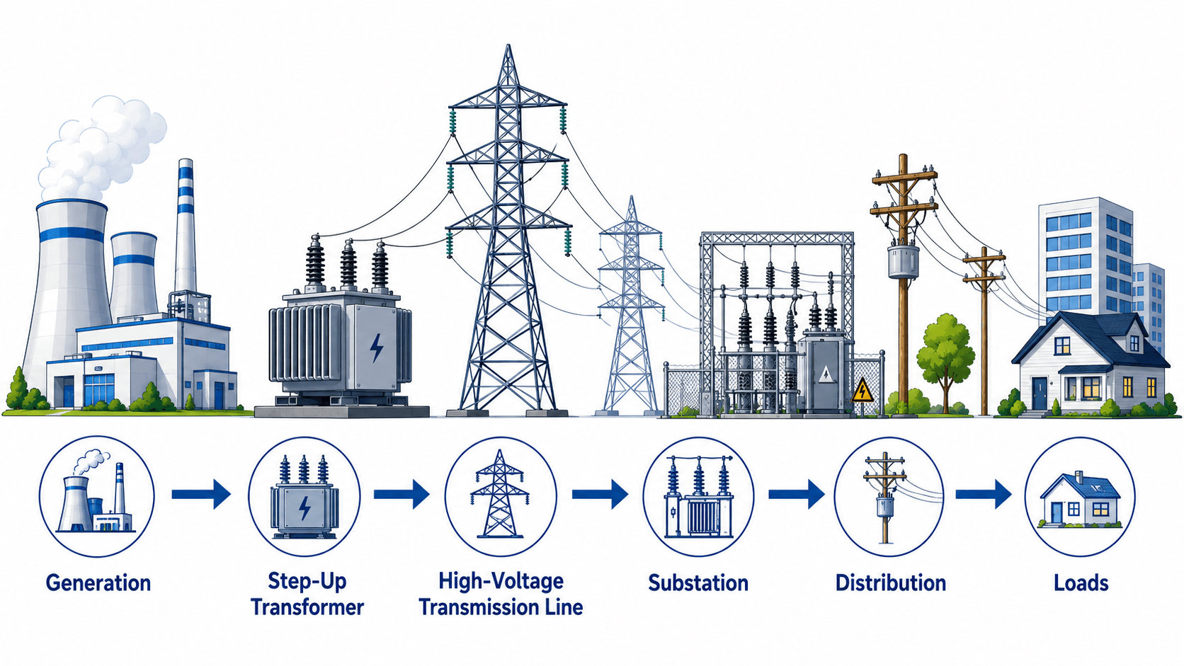
Read the power path from left to right: voltage is raised for efficient long-distance transfer, then reduced again so local distribution equipment and customer loads can use it safely.
What Is a Transmission Line?
A transmission line is a power system circuit built to carry large amounts of electrical energy across long distances. In utility-scale systems, transmission lines connect generating plants, renewable energy projects, switching stations, substations, interties, and large load areas. They may be overhead, underground, submarine, alternating current, or direct current depending on the project.
The visible part of an overhead transmission line is usually a set of conductors supported by steel towers or poles. The engineering system is larger than that: it also includes insulation, grounding, shielding, protection relays, breakers, terminal equipment, communications, right-of-way, access, and operating limits. A technically correct explanation must include both the electrical model and the physical corridor.
| System level | Primary purpose | Typical engineering concern |
|---|---|---|
| Generation connection | Moves power from a plant, wind farm, solar project, or interconnection point into the grid. | Transformer rating, interconnection voltage, protection, stability, and export limit. |
| Bulk transmission | Transfers high power across long distances between major grid nodes. | Thermal loading, voltage profile, reactive power, losses, contingency limits, and right-of-way. |
| Substation interface | Connects lines to buses, breakers, transformers, relays, and switching equipment. | Fault clearing, switching arrangement, insulation coordination, grounding, and maintainability. |
Typical Transmission Line Voltage Levels
Transmission line voltage depends on the utility system, distance, transferred power, interconnection requirements, and equipment class. In the United States, common transmission voltages include 115 kV, 138 kV, 161 kV, 230 kV, 345 kV, 500 kV, and 765 kV, with lower sub-transmission voltages used in some regional systems and higher-voltage HVDC used for special corridors.
| Voltage category | Common examples | Typical use |
|---|---|---|
| Sub-transmission | 34.5 kV, 46 kV, 69 kV | Regional transfer, large load supply, or interface between transmission and distribution systems. |
| High-voltage transmission | 115 kV, 138 kV, 161 kV, 230 kV | Bulk power transfer between substations, generation interconnections, and regional grid nodes. |
| Extra-high-voltage transmission | 345 kV, 500 kV, 765 kV | Long-distance bulk corridors, major interties, and high-capacity network backbones. |
| HVDC transmission | Project-specific, often hundreds of kV | Long-distance point-to-point transfer, submarine cables, renewable export corridors, or asynchronous grid ties. |
Voltage class is not selected from distance alone. Engineers also consider required MW transfer, losses, insulation level, equipment availability, right-of-way, grid strength, short-circuit duty, reactive power, and expansion plans.
Main Parts of an Overhead Transmission Line
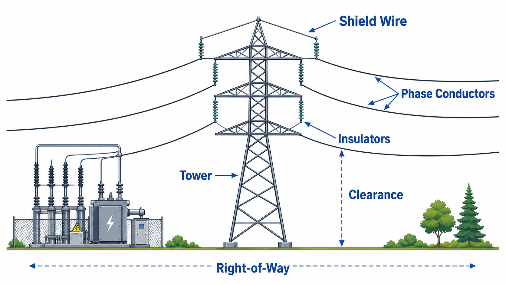
The most common image of a transmission line is an overhead tower carrying several conductors across open land. Each visible part has a specific engineering role: conductors carry current, insulators maintain electrical separation, towers provide height and structure, shield wires reduce lightning exposure, and the right-of-way protects the corridor around the energized line.
| Component | What it does | Engineering issue to watch |
|---|---|---|
| Phase conductors | Carry three-phase power along the line. | Conductor size affects ampacity, resistance, sag, losses, and corona performance. |
| Insulators | Hold energized conductors away from grounded structures. | Insulator selection depends on voltage, contamination, lightning, switching surges, and mechanical load. |
| Towers or poles | Support conductors and maintain physical clearance. | Structure design must handle wind, ice, line tension, terrain, access, and maintenance requirements. |
| Shield wire | Provides a grounded path above phase conductors to reduce lightning exposure. | Shielding angle, grounding, and tower footing resistance affect lightning performance. |
| Right-of-way | Provides corridor width for safety, access, vegetation control, and clearances. | ROW constraints can control route selection, constructability, reliability, and project cost. |
Types of Transmission Lines
Transmission lines are grouped by construction, current type, circuit arrangement, and network role. A rural overhead AC line, an urban underground cable, a submarine export cable, and an HVDC intertie can all be transmission lines, but they behave differently and require different design checks.
| Transmission line type | Where it is used | Key engineering tradeoff |
|---|---|---|
| Overhead AC transmission line | Common bulk power corridors, regional networks, and utility interconnections. | Usually cost-effective and accessible, but requires right-of-way, visual impact review, weather design, and clearance management. |
| Underground transmission cable | Urban corridors, constrained rights-of-way, sensitive locations, and short high-value crossings. | Reduces overhead visual impact but increases cost, thermal complexity, capacitance, repair time, and installation difficulty. |
| Submarine transmission cable | Offshore wind, island interconnections, bay crossings, and underwater grid ties. | Requires specialized cable design, installation vessels, protection from anchors, and difficult fault repair logistics. |
| HVDC transmission line | Long-distance point-to-point transfer, asynchronous grid ties, submarine links, and renewable export paths. | Offers controllable power flow, but converter stations, controls, filtering, and DC protection add complexity. |
| Double-circuit overhead line | Corridors where more transfer capacity is needed on the same structure or right-of-way. | Improves corridor utilization but can increase outage exposure if both circuits share the same structure or corridor risk. |
Transmission Lines vs Distribution Lines
Transmission and distribution lines both move electricity, but they serve different parts of the grid. Transmission lines move bulk power over longer distances at higher voltage. Distribution lines deliver power locally at lower voltage after substations have reduced the voltage for neighborhoods, campuses, commercial districts, and industrial loads.
| Comparison point | Transmission lines | Distribution lines |
|---|---|---|
| Role in the grid | Move bulk power between generation, substations, interties, and major load centers. | Deliver power from local substations to customers and smaller loads. |
| Voltage level | Usually high voltage or extra-high voltage depending on the system. | Lower voltage than transmission, then stepped down again near end users. |
| Primary design concern | Long-distance transfer, stability, voltage control, losses, line loading, and fault isolation. | Customer voltage, feeder loading, local reliability, service transformers, protection coordination, and voltage regulation. |
| Common structure | Large towers, monopoles, underground cables, submarine cables, or dedicated corridors. | Wood poles, concrete poles, pad-mounted equipment, underground ducts, and local service conductors. |
| Related Turn2Engineering resource | Transmission line protection explains how high-voltage lines are isolated during faults. | Distribution lines explains the lower-voltage delivery side of the grid. |
Why Transmission Lines Use High Voltage
The main reason transmission lines use high voltage is to reduce current for a given power transfer. Lower current reduces conductor heating because real power loss in the conductor is proportional to the square of current. That is why the grid commonly uses step-up transformers near generation and step-down transformers near load centers.
- \(P\) Three-phase real power transferred by the line, usually expressed in MW for utility transmission.
- \(V_L\) Line-to-line voltage. Higher voltage allows lower current for the same real power transfer.
- \(I_L\) Line current. Current drives conductor heating, voltage drop, and many equipment loading limits.
- \(R\) Effective conductor resistance over the line length. Resistance changes with conductor material, size, temperature, and length.
Numerical example: 100 MW at 115 kV vs 230 kV
Assume a three-phase line transfers 100 MW at a 0.95 power factor. At 115 kV, the approximate line current is:
If the same power is transferred at 230 kV with the same power factor, the approximate current becomes:
Doubling voltage roughly halves the current. Because resistive conductor loss follows \(I^2R\), the loss ratio is approximately:
That means the higher-voltage case would have about one-quarter of the resistive loss for the same conductor resistance. In real projects, the final comparison also includes equipment cost, insulation, clearance, right-of-way, reactive power, and system planning requirements.
Do not treat high voltage as automatically “better” in every case. Higher voltage improves transfer efficiency, but it also increases insulation requirements, clearance distances, switching surge concerns, equipment cost, and right-of-way complexity.
Transmission Line Parameters: R, L, C, and G
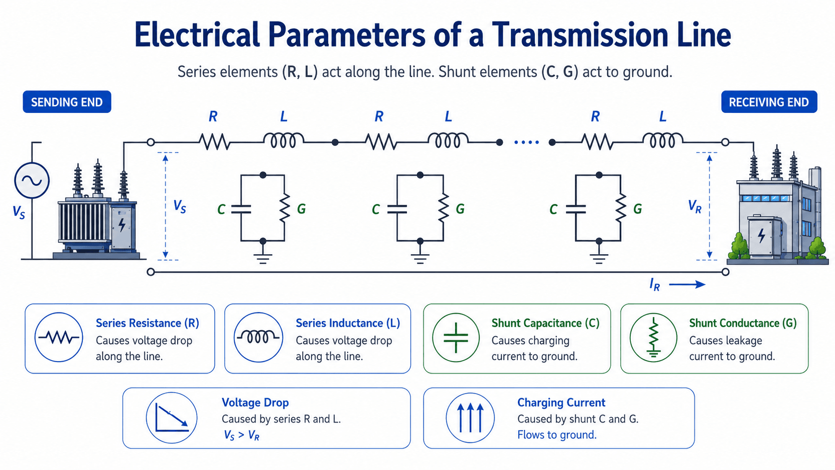
A transmission line is modeled with four core electrical parameters: resistance \(R\), inductance \(L\), capacitance \(C\), and conductance \(G\). Short lines can often be approximated with simple series impedance, while longer lines require shunt capacitance and distributed behavior because the line itself stores and exchanges electric and magnetic energy.
| Parameter | Physical meaning | Practical effect |
|---|---|---|
| Resistance \(R\) | Opposition to current flow in the conductor. | Creates \(I^2R\) losses, heating, voltage drop, and thermal loading concerns. |
| Inductance \(L\) | Magnetic field effect around the conductors. | Contributes to line reactance, voltage drop, reactive power behavior, and transfer limits. |
| Capacitance \(C\) | Electric field storage between conductors and between conductors and ground. | Creates charging current, affects voltage profiles, and becomes important on long lightly loaded lines. |
| Conductance \(G\) | Leakage path through insulation, air, contamination, or surface effects. | Usually small in overhead line models, but relevant to losses, insulation condition, and abnormal leakage paths. |
Short, Medium, and Long Transmission Line Models
Line length changes how accurately the circuit must be modeled. A short line may be close enough to a series impedance model for many introductory calculations, while a long line behaves like a distributed electrical system. Choosing the wrong model can make voltage regulation, reactive power, and loading results misleading.
| Model type | Use this when | What the model includes | What can be missed |
|---|---|---|---|
| Short line model | The line is short enough that shunt capacitance does not materially affect the result. | Series resistance and inductive reactance. | Charging current, light-load voltage rise, and shunt effects are usually not captured. |
| Medium line model | The line is long enough that capacitance matters, but lumped approximations are acceptable. | Series impedance plus lumped shunt capacitance, often as nominal-pi or nominal-T models. | Still approximates distributed behavior and may be insufficient for very long corridors. |
| Long line model | The line is long enough that impedance and admittance should be treated as distributed. | Distributed series impedance and shunt admittance along the line length. | Requires more careful data and assumptions, but better represents long-distance voltage and reactive effects. |
Why long lines behave differently
On longer transmission lines, capacitance is no longer a small detail. Charging current can exist even when load is light, and voltage behavior may depend strongly on line length, load level, compensation, and system strength at each end. This is why transmission planning relies on trusted line data and power flow models rather than only simple hand equations.
Where ABCD parameters fit
For a more formal transmission line model, sending-end voltage and current can be related to receiving-end voltage and current using ABCD parameters. This is a compact way to represent the behavior of a line section, especially when comparing nominal-pi, nominal-T, and long-line models.
In practical studies, these parameters are usually embedded inside power system software or line models. The important engineering point is that \(V_S\), \(I_S\), \(V_R\), and \(I_R\) are linked by the line’s impedance, admittance, length, and loading condition.
For the broader study workflow behind bus voltages, MW/MVAR flow, and line loading, see load flow analysis.
Voltage Drop, Losses, and Efficiency
Transmission line performance is often judged by delivered voltage, real power losses, equipment loading, and transfer capability. Voltage drop is the reduction in voltage caused by line impedance under load. Loss is the real power converted to heat and other non-useful forms. The two are related, but they are not the same engineering quantity.
Efficiency improves when the same useful power is delivered with lower losses. In transmission work, that can involve higher voltage, larger conductors, improved power factor, reactive compensation, better operating dispatch, reconductoring, new lines, or changes to how power flows across the network.
| Performance issue | What causes it | Engineering response |
|---|---|---|
| Conductor heating | High current flowing through conductor resistance. | Check ampacity, emergency ratings, ambient conditions, sag, and loading under contingencies. |
| Voltage drop | Series impedance and load current, especially with reactive power flow. | Review voltage profile, compensation, transformer taps, operating cases, and receiving-end voltage limits. |
| Reactive power effects | Line inductance, line capacitance, load power factor, and system strength. | Evaluate shunt reactors, capacitor banks, static VAR equipment, transformer taps, and operating limits. |
| Corona and high-voltage effects | High electric field stress near conductors, especially at higher voltage and unfavorable weather. | Review conductor bundle, spacing, voltage class, surface condition, audible noise, and radio interference limits. |
For a deeper look at system-level losses, see power system efficiency. For voltage behavior across operating conditions, see voltage regulation.
What Limits the Capacity of a Transmission Line?
The capacity of a transmission line is not always the same as the conductor ampacity. A line may be thermally acceptable but still limited by voltage stability, angular stability, contingency loading, relay protection, sag clearance, or operating procedures. The controlling limit depends on the system case being studied.
| Limiting factor | Usually controls when | What engineers check |
|---|---|---|
| Thermal limit | The conductor heats up under high current, especially during peak load or emergency operation. | Conductor temperature, ampacity, wind speed, ambient temperature, solar heating, emergency rating, and sag. |
| Sag and clearance | Higher conductor temperature causes expansion and reduced ground or crossing clearance. | Worst-case conductor temperature, terrain, crossings, roadways, vegetation, structures, and right-of-way envelope. |
| Voltage drop | Receiving-end voltage becomes too low during heavy loading or poor power factor conditions. | Voltage profile, transformer taps, reactive support, system strength, load power factor, and operating scenario. |
| Voltage stability | The line is long, heavily loaded, or connected to a weak receiving-end system. | Reactive margin, P-V curves, contingency cases, compensation, and load-flow sensitivity. |
| Angular stability | Large power transfers occur across long AC paths between generation and load areas. | System strength, power angle, transient stability, clearing time, generator response, and contingency results. |
| Protection and fault clearing | Relay reach, fault current, weak infeed, series compensation, or communication-assisted protection affects security. | Distance relay zones, pilot schemes, breaker clearing time, CT/VT inputs, backup protection, and power swing blocking. |
| Right-of-way or constructability | The corridor cannot support the required structures, clearances, access, or environmental constraints. | Route constraints, land rights, access roads, vegetation, crossings, environmental restrictions, and maintenance needs. |
A transmission line rating is not a single universal number. Normal ratings, emergency ratings, seasonal ratings, contingency limits, voltage limits, and stability limits may all describe different operating conditions.
AC and HVDC Transmission Lines
Most transmission networks use high-voltage alternating current because AC voltage can be transformed efficiently and integrated into synchronous grids. High-voltage direct current, or HVDC, is used when its benefits justify converter stations, controls, and protection complexity.
| Transmission type | Where it is useful | Key tradeoff |
|---|---|---|
| High-voltage AC | Most interconnected grid transmission, substation networks, regional lines, and conventional bulk power paths. | Transformer-friendly and widely standardized, but long lines require reactive power and voltage control. |
| HVDC | Long-distance bulk transfer, submarine cables, asynchronous grid ties, and some renewable integration corridors. | Can control power flow well, but converter stations add cost, complexity, controls, harmonics, and protection challenges. |
| Underground or submarine cable | Urban constraints, water crossings, offshore connections, and sensitive corridors. | Can reduce visual impact, but thermal, capacitance, repair access, and cost constraints are significant. |
Senior Engineer Review Checklist for Transmission Lines
A useful transmission line review checks more than whether the conductor can carry current. The line must be electrically acceptable, mechanically safe, protectable, maintainable, and realistic under normal, emergency, and abnormal operating conditions.
Start with the required power transfer and voltage class, then check electrical loading, voltage profile, losses, reactive power, protection, physical clearance, environmental exposure, access, and contingency operation. A line that passes one check can still fail another.
| Transmission line check | What to look for | Why it matters |
|---|---|---|
| Voltage class and insulation | Nominal voltage, surge expectations, insulator selection, air clearances, and switching surge exposure. | Voltage class drives physical size, equipment selection, safety clearances, and insulation coordination. |
| Thermal ampacity | Normal and emergency current, ambient temperature, wind, solar heating, conductor temperature, and sag. | Overheating can reduce clearance, damage conductors, and violate operating limits. |
| Voltage and reactive power | Receiving-end voltage, charging current, VAR flow, compensation, and operating cases. | Long lines can create voltage control problems that are not obvious from MW transfer alone. |
| Protection and fault clearing | Relay zones, breaker arrangement, CT/VT inputs, communication-assisted schemes, and backup protection. | Faults must be cleared selectively and quickly enough to protect equipment and maintain stability. |
| Right-of-way and access | Corridor width, vegetation control, terrain, land use, crossings, access roads, and maintenance constraints. | The best electrical route may be impractical if it cannot be built, accessed, or maintained safely. |
| System contingency performance | N-1 loading, rerouted flows, outage cases, stability limits, and post-contingency voltage behavior. | Transmission lines are part of a network, so a single outage can shift loading to other paths. |
Engineering Judgment and Field Reality
Textbook diagrams show straight lines, ideal sources, and clean impedances. Real transmission corridors include terrain, vegetation, weather, permitting, outages, access restrictions, aging equipment, tower grounding variation, conductor temperature changes, contaminated insulators, relay settings, and neighboring lines that influence mutual coupling and fault behavior.
A transmission line can be electrically adequate on a normal load-flow case and still be unacceptable because of sag clearance, lightning performance, vegetation risk, access limitations, protection coordination, or emergency loading under a nearby outage.
What experienced reviewers watch for
- Line ratings based on unrealistic ambient temperature, wind, or conductor temperature assumptions.
- Voltage studies that ignore low-load, light-load, or open-ended charging current behavior.
- Protection settings that look correct on paper but are vulnerable to load encroachment, weak infeed, communication failure, or high-resistance faults.
- Route choices that underestimate maintenance access, vegetation management, wildfire exposure, or crossing complexity.
When This Breaks Down
Simplified transmission line explanations break down when the line is long, highly loaded, weakly supported by the surrounding grid, heavily compensated, exposed to severe weather, or operated near stability and voltage limits. At that point, the line must be treated as part of a dynamic network rather than an isolated conductor.
- Long lines: Distributed capacitance, charging current, voltage rise, and reactive power behavior can dominate simple series-impedance assumptions.
- Heavy transfers: Thermal limits may not be the only limit; voltage stability, angular stability, and contingency loading can become controlling constraints.
- Unusual corridors: Underground, submarine, compact urban, or heavily constrained routes can behave differently from typical overhead transmission lines.
- Protection edge cases: Weak infeed, mutual coupling, series compensation, power swings, and communication problems can affect line protection performance.
Common Mistakes and Practical Checks
Transmission line mistakes often come from treating the line as a simple wire instead of a high-voltage system with electrical, mechanical, protection, and operational constraints. The most useful check is to ask which limit actually controls the line under the case being studied.
| Common mistake | Why it is wrong | Better engineering check |
|---|---|---|
| Assuming higher voltage only means higher danger | Higher voltage also reduces current for the same power transfer, which reduces resistive losses. | Check both the efficiency benefit and the added insulation, clearance, and equipment requirements. |
| Confusing voltage drop with power loss | Voltage drop is a voltage profile issue; loss is real power converted to heat or other non-useful forms. | Review receiving-end voltage, MW loss, MVAR flow, and conductor loading separately. |
| Ignoring shunt capacitance on long lines | Charging current and voltage rise can be important when the line is long or lightly loaded. | Use an appropriate medium or long line model and review reactive compensation needs. |
| Assuming line capacity equals conductor ampacity | Ampacity may not be the controlling limit if voltage stability, sag, protection, or contingency cases control first. | Compare thermal rating, sag clearance, voltage behavior, relay constraints, and N-1 transfer limits. |
| Checking ampacity but not sag clearance | A thermally loaded conductor expands and sags, which can reduce ground or crossing clearance. | Review conductor temperature, weather case, ruling span, clearance envelope, and right-of-way constraints. |
| Designing protection as an afterthought | Fault clearing depends on relays, breakers, CTs, VTs, communications, and backup schemes. | Coordinate the line electrical model with the protection design and terminal equipment. |
Do not evaluate a transmission line from normal operating current alone. The controlling issue may be voltage stability, emergency loading, sag, fault clearing, reactive power, right-of-way, or a contingency case.
Useful References and Design Context
Transmission line engineering is usually governed by utility standards, owner criteria, interconnection requirements, protection philosophy, reliability practices, and project-specific routing constraints. Public references are useful for understanding the basic grid role of high-voltage transmission, while final design requires project-specific criteria and qualified engineering review.
- U.S. Department of Energy: DOE overview of electric transmission and distribution infrastructure explains transmission networks, substations, transformers, switching equipment, and common high-voltage transmission levels used in the electric grid.
- Project-specific criteria: Transmission line designs commonly depend on utility design standards, interconnection studies, route constraints, environmental conditions, equipment ratings, and operating procedures.
- Engineering use: Engineers use references and project criteria to move from the simple power-transfer concept to a complete line design, model, protection scheme, and operating limit.
Frequently Asked Questions
A transmission line is the high-voltage electrical path used to move bulk power from generation sources to substations and major load centers. It includes conductors, towers or poles, insulators, shield wires, grounding, right-of-way, and terminal equipment that allow large amounts of power to travel efficiently over long distances.
Transmission lines use high voltage because, for the same power transfer, higher voltage allows lower current. Lower current reduces conductor heating losses because real power loss rises with the square of current, so high-voltage operation improves long-distance power delivery efficiency.
Transmission lines move bulk power over longer distances at higher voltages, usually between generation plants, renewable resources, substations, and major grid nodes. Distribution lines operate at lower voltages and deliver power from local substations to homes, businesses, and smaller end-use loads.
The main electrical parameters are resistance, inductance, capacitance, and conductance. Resistance and inductance act along the line and influence voltage drop and losses, while capacitance and conductance act between the conductors and ground and influence charging current, leakage, and long-line behavior.
Transmission line capacity can be limited by conductor heating, sag clearance, voltage drop, voltage stability, angular stability, relay protection, right-of-way constraints, or contingency loading. The controlling limit depends on line length, voltage level, conductor type, grid strength, weather, and operating scenario.
Summary and Next Steps
Transmission lines are the high-voltage backbone of the power system. They allow bulk electrical power to move from generation and interconnection points to substations and major load centers while balancing efficiency, voltage control, reliability, and physical corridor requirements.
The most important concepts are voltage level, current, conductor resistance, line impedance, shunt capacitance, thermal loading, sag, right-of-way, protection, and operating limits. A strong review treats the line as both an electrical model and a real field asset exposed to weather, faults, access limits, and changing grid conditions.
Where to go next
Continue your learning path with related Turn2Engineering resources.
-
Transmission Line Protection
Learn how relays, zones, breakers, and communication schemes detect and isolate faults on high-voltage transmission circuits.
-
Load Flow Analysis
Understand how engineers evaluate bus voltages, MW/MVAR flows, line loading, and system losses across a network.
-
Distribution Lines
Compare the lower-voltage delivery side of the grid with the bulk transmission system.