Key Takeaways
- Core idea: Switchgear is not one device; it is an equipment assembly used to control, protect, meter, and isolate electrical circuits.
- Engineering use: Engineers apply switchgear to distribute power, clear faults, isolate equipment for maintenance, and keep healthy feeders energized.
- What controls it: Voltage class, continuous current, available fault current, interrupting rating, bus rating, enclosure type, and protection coordination drive switchgear selection.
- Practical check: A switchgear lineup is only as reliable as its ratings, relay settings, maintenance condition, labels, access clearances, and field documentation.
Table of Contents
Introduction
Switchgear is the electrical equipment assembly that controls, protects, meters, and isolates power circuits. In a power system, it typically combines breakers, switches, fuses, busbars, relays, instrument transformers, controls, cable compartments, and grounding so faults can be cleared and equipment can be operated safely.
Where Switchgear Fits in a Power System
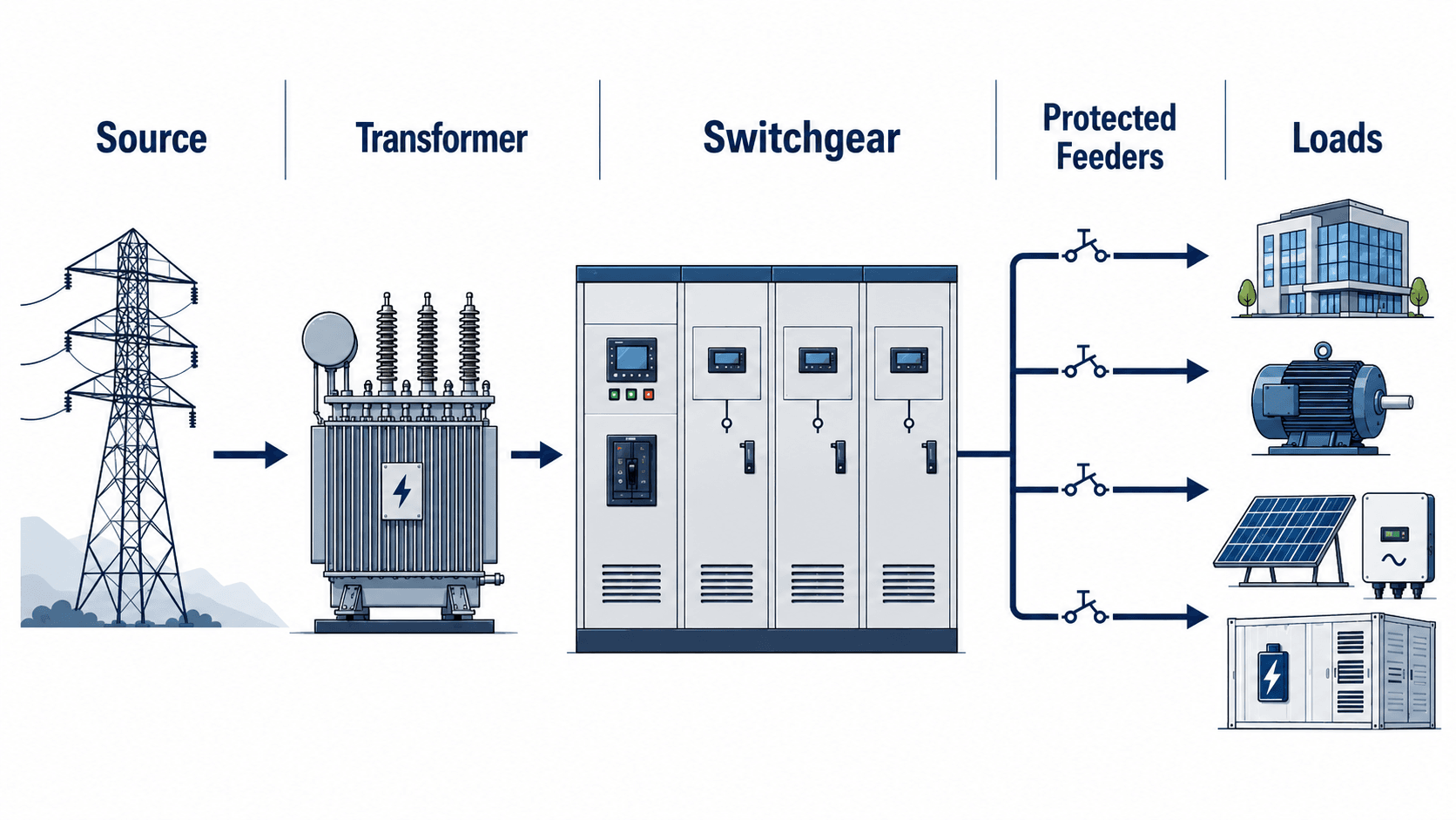
Notice that the switchgear is not simply a breaker symbol. It is a central lineup that connects the incoming source to multiple protected outgoing circuits.
What Is Switchgear?
Switchgear is a grouped assembly of electrical switching, interrupting, protection, metering, and control equipment. In practical power systems, it is used to energize circuits, de-energize equipment, interrupt fault current, isolate sections for maintenance, and organize power distribution through a safe enclosure.
A useful way to think about switchgear is as a controlled boundary between a source and a protected zone. On one side is the incoming service, transformer, generator, feeder, or bus. On the other side are outgoing feeders and loads. The switchgear provides the devices and logic needed to decide what remains energized and what must be disconnected when conditions change.
The purpose of switchgear is not just to turn power on and off. Its real engineering value is selective control: interrupt the right circuit, at the right rating, fast enough to limit damage, while keeping the rest of the system available when practical.
How Switchgear Appears on a One-Line Diagram
On a one-line diagram, switchgear is usually shown as an incoming source, a main breaker or main switch, a bus, and multiple outgoing feeder breakers or switches. Medium-voltage switchgear may also show current transformers, voltage transformers, protective relays, tie breakers, bus sections, and feeder names.
This simplified drawing is not just documentation. Engineers use it to understand the protection zones, switching sequence, load paths, normal operating configuration, and what portions of the system should remain energized after a fault.
| One-line diagram item | What it represents | Why it matters |
|---|---|---|
| Incoming breaker or main switch | The primary device connecting the switchgear to the source, transformer, generator, or upstream feeder. | Defines how the lineup is energized and how the entire bus can be disconnected. |
| Bus | The common electrical connection feeding multiple outgoing circuits. | Bus rating and bracing affect every feeder connected to the lineup. |
| Feeder breakers | Protective and switching devices for downstream circuits. | Each feeder breaker defines a protection zone and outage boundary. |
| CTs, VTs, and relays | Measurement and protection elements used for metering and trip logic. | Ratios, wiring, and relay settings affect how faults are detected and cleared. |
| Tie breaker or bus tie | A device that can connect two switchgear buses or sections. | Improves operating flexibility but changes available fault current and coordination assumptions. |
How Switchgear Works During a Fault
During normal operation, switchgear carries load current through busbars, breakers, and outgoing feeders. During an abnormal condition, such as a short circuit or ground fault, the protection system must detect the condition, command interruption, and isolate the affected circuit before damage spreads.
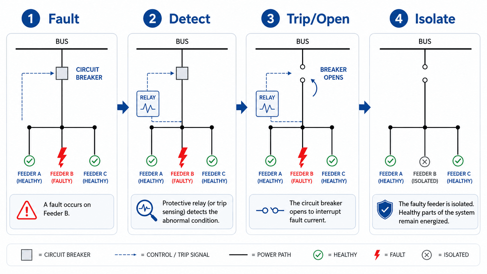
Fault detection
In low-voltage equipment, the breaker trip unit may sense current directly. In medium-voltage and higher-voltage switchgear, protective relays often receive current and voltage signals from current transformers and voltage transformers. The relay compares those measurements against its settings and logic.
Interruption and isolation
When the trip condition is met, the breaker opens and interrupts current. The switchgear enclosure, bus structure, insulation, breaker mechanism, and protective device ratings must all be suitable for the voltage and available short-circuit current at that location.
Selective protection
Good switchgear application is not just about tripping quickly. It is about tripping the correct device. If the feeder breaker clears the fault before the main breaker trips, the faulty circuit is isolated while the rest of the lineup can often remain energized.
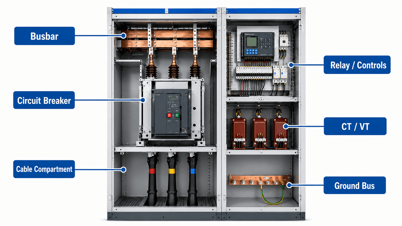
Main Components Inside Switchgear
A switchgear lineup is usually divided into functional compartments. Exact construction depends on voltage class, manufacturer, insulation method, and whether the equipment is low-voltage, medium-voltage, metal-clad, metal-enclosed, or arc-resistant.
| Switchgear component | What it does | Why it matters in practice |
|---|---|---|
| Busbar | Conducts power through the lineup and connects incoming and outgoing sections. | Bus rating, bracing, insulation, and fault withstand capability affect the entire switchgear lineup. |
| Circuit breaker | Opens and closes a circuit and interrupts fault current within its rating. | The breaker must match the voltage, continuous current, interrupting duty, control power, and application requirements. |
| Protective relay or trip unit | Detects abnormal conditions and initiates breaker operation. | Incorrect settings can cause nuisance trips, failure to trip, or poor selectivity with upstream and downstream protection. |
| CTs and VTs/PTs | Provide scaled current and voltage signals for relays, metering, and controls. | Instrument transformer ratio, burden, polarity, and wiring errors can affect protection performance. |
| Cable compartment | Provides space for incoming or outgoing cable terminations. | Termination quality, bending space, clearances, shielding, grounding, and labeling affect reliability and maintainability. |
| Ground bus | Provides a bonding and grounding path for equipment enclosures and fault current return paths. | Loose, corroded, or missing grounding connections can create serious safety and protection problems. |
Types of Switchgear
Switchgear is usually classified by voltage class, construction, and insulation or interruption method. Those classifications matter because the equipment ratings, physical clearances, maintenance needs, arc-flash behavior, and protection schemes can change significantly.
Switchgear by voltage class
| Type | Common use | Engineering implication |
|---|---|---|
| Low-voltage switchgear | Commercial buildings, industrial facilities, data centers, service entrances, motor control areas, and facility distribution. | Often focuses on breaker trip units, short-circuit current rating, selective coordination, maintenance access, and arc-flash reduction features. |
| Medium-voltage switchgear | Substations, large campuses, industrial plants, renewable energy facilities, feeders, transformers, motors, and collector systems. | Frequently uses relays, CTs, VTs, vacuum interrupters, metal-clad construction, and detailed protection coordination. |
| High-voltage switchgear | Utility substations, transmission interconnections, and high-voltage switching yards. | Insulation coordination, switching surges, breaker duty, clearances, and system protection studies become central design concerns. |
The practical difference between low-voltage and medium-voltage switchgear is not just voltage. It affects insulation, breaker technology, relay strategy, compartment design, maintenance methods, working clearances, and the studies engineers rely on before approving equipment.
Switchgear by construction or insulation method
| Switchgear category | What it generally means | Where engineers pay attention |
|---|---|---|
| Air-insulated switchgear | Uses air as the primary insulating medium between energized parts. | Requires adequate clearances, good insulation condition, clean compartments, and proper environmental control. |
| Gas-insulated switchgear | Uses insulating gas inside sealed compartments to reduce space and improve dielectric performance. | Useful where compactness is important, but gas handling, leak management, and manufacturer procedures matter. |
| Vacuum-interrupting switchgear | Uses vacuum interrupters, commonly in medium-voltage breakers. | Breaker mechanism condition, contact wear, insulation integrity, and relay coordination remain important even when interruption technology is robust. |
| Arc-resistant switchgear | Designed to redirect or contain arc energy under specified test conditions. | Ratings only apply when doors, covers, exhaust paths, installation details, and maintenance condition match the tested configuration. |
Switchgear vs Switchboard vs Panelboard vs MCC
Many readers use these terms interchangeably, but they do not mean the same thing in engineering practice. The practical difference is usually tied to equipment construction, accessibility, protective-device type, short-circuit duty, serviceability, and the role the assembly plays in the distribution system.
| Equipment | Typical role | Practical distinction |
|---|---|---|
| Switchgear | Primary control, protection, switching, and isolation for larger or more critical circuits. | Often compartmentalized and designed for higher duty, maintainability, protective relays, drawout breakers, and defined fault-interruption performance. |
| Switchboard | Distribution of power from service equipment, transformers, generators, or large feeders. | Typically a distribution assembly with protective devices and bus, but not always built with the same compartmentalization or interrupting arrangement as switchgear. |
| Panelboard | Branch-circuit and feeder distribution for buildings and equipment. | Usually smaller, wall-mounted or cabinet-mounted, and used closer to final branch loads than major switchgear lineups. |
| Motor control center | Grouping of motor starters, overload protection, drives, and control buckets for multiple motors. | Focused on motor control rather than serving as the primary switchgear lineup for major source-to-feeder protection. |
| Disconnect switch | Manual or motor-operated isolation point for a circuit or piece of equipment. | A disconnect may be part of a switchgear lineup, but by itself it is not the complete protection and distribution assembly. |
Do not classify equipment by appearance alone. Review the nameplate, one-line diagram, listing, voltage class, protective devices, interrupting rating, construction type, and project specifications.
Switchgear Ratings Engineers Check First
The most important switchgear details are usually found on the nameplate, equipment drawings, protection study, and one-line diagram. These ratings determine whether the lineup can carry normal load and survive credible abnormal conditions.
| Rating or data point | What it tells you | Engineering check |
|---|---|---|
| Rated voltage | The maximum system voltage class the switchgear is designed to serve. | Match the equipment voltage class to the system voltage, grounding method, and insulation requirements. |
| Continuous current rating | The current the bus, breaker, or section can carry under defined conditions. | Compare against load current, future load growth, ambient conditions, and equipment ventilation. |
| Interrupting rating | The maximum fault current the breaker can interrupt safely. | Must exceed the available short-circuit current at the switchgear location. |
| Short-time or withstand rating | The ability of bus and equipment to withstand fault current for a short duration. | Coordinate with protective device clearing times and upstream fault contribution. |
| Bus bracing | The mechanical strength of bus supports during high fault forces. | Important when available fault current is high or utility/source changes increase duty. |
| Basic insulation level | A dielectric strength measure used especially in medium-voltage and high-voltage contexts. | Check insulation coordination where surges, switching events, or exposed equipment matter. |
| Control voltage | The voltage used by trip coils, close coils, relays, lights, meters, and controls. | Loss of control power can prevent a breaker from operating even if the power circuit is properly rated. |
| Enclosure rating | The environmental protection level for indoor, outdoor, dusty, wet, or corrosive service. | Match the enclosure to the installation environment, not just the electrical load. |
| Arc-resistant rating | The tested ability to manage internal arcing energy under specified conditions. | Only valid when installation, doors, covers, exhaust paths, and maintenance condition match the tested arrangement. |
How Engineers Select Switchgear
Switchgear selection starts with the electrical system requirements and ends with a coordinated, maintainable equipment lineup. The key is to match the equipment to both normal operating current and credible abnormal conditions.
- Voltage class: The insulation system and equipment rating must match the system voltage and grounding method.
- Continuous current: The bus, breaker, and feeder ratings must support the expected load and future capacity where required.
- Available fault current: The interrupting rating and withstand rating must exceed the short-circuit duty at the equipment location.
- Protection coordination: Breakers, relays, fuses, and upstream devices should trip selectively where the system requires continuity.
- Environment: Indoor, outdoor, corrosive, dusty, humid, high-altitude, and temperature conditions can change enclosure and maintenance requirements.
- Access and maintainability: Cable space, working clearances, racking method, labeling, and documentation affect long-term safety and serviceability.
A breaker with the correct amp rating is not enough. The complete switchgear assembly must also have suitable voltage rating, short-circuit rating, bus rating, enclosure rating, trip logic, control power, grounding, and installation configuration.
Senior Engineer Switchgear Review Checklist
A practical switchgear review checks whether the lineup can safely carry load, interrupt faults, coordinate with the system, and remain maintainable over its life. The checklist below is useful during design review, equipment replacement, commissioning, or field troubleshooting.
Start with the one-line diagram, verify system voltage and available fault current, check switchgear ratings, review the protection scheme, then confirm field details such as clearances, labeling, grounding, control power, maintenance condition, and documentation.
| Switchgear review item | What to look for | Why it matters |
|---|---|---|
| Voltage and insulation rating | Nameplate voltage, basic insulation level where applicable, system grounding, and equipment class. | Underrated insulation can fail during normal operation, switching events, or fault conditions. |
| Short-circuit and interrupting rating | Available fault current at the lineup compared with breaker interrupting rating and assembly withstand rating. | Switchgear must safely interrupt and withstand the maximum credible fault duty at its location. |
| Bus and continuous current rating | Main bus, feeder bus, breaker frame, sensor or trip unit rating, and expected loading. | Overloaded bus or mismatched breaker hardware can lead to overheating and premature failure. |
| Relay and trip settings | Pickup, delay, instantaneous, differential, ground-fault, and interlocking logic where used. | Settings determine whether the correct breaker trips and whether healthy portions of the system stay energized. |
| Arc-flash study assumptions | Equipment labels, fault current, clearing time, working distance, maintenance mode, and recent system changes. | Labels can become misleading when settings, utility contribution, transformers, or equipment configurations change. |
| Cable terminations and compartment condition | Torque, insulation, stress cones, shielding, bending space, phasing, and visible heating or tracking. | Many switchgear failures start at terminations, contamination, loose joints, or degraded insulation. |
| Grounding and bonding | Ground bus continuity, bonding jumpers, equipment grounding conductor, and enclosure bonding. | Grounding supports fault clearing, touch-voltage control, and safe operation of metal enclosures. |
| Maintenance access and documentation | Working clearances, racking method, spare parts, manuals, one-line diagrams, and breaker test records. | Switchgear that cannot be safely accessed, tested, or identified is difficult to maintain correctly. |
Common Switchgear Failure Modes
Switchgear failures often start as small mechanical, thermal, insulation, or documentation problems. The goal of inspection and maintenance is to catch these warning signs before they turn into a forced outage, arc-flash event, or equipment replacement.
| Failure mode | Typical cause | Field warning sign | Why it matters |
|---|---|---|---|
| Loose bus joint | Thermal cycling, poor torque, vibration, or aging hardware. | Hot spot on infrared scan, discoloration, or damaged insulation near a joint. | Can escalate into arcing, bus damage, or a line-up-wide outage. |
| Contaminated insulation | Dust, moisture, conductive debris, rodents, chemical contamination, or poor housekeeping. | Tracking marks, surface deposits, odor, corona evidence, or insulation discoloration. | Reduces dielectric strength and increases the likelihood of phase-to-ground or phase-to-phase failure. |
| Breaker mechanism failure | Lack of exercise, worn mechanism parts, dried lubrication, or poor maintenance. | Slow operation, failed trip test, racking difficulty, or inconsistent open/close indication. | A rated breaker is not protective if it cannot open when commanded. |
| Control power failure | Battery charger issue, blown control fuse, wiring fault, failed trip coil, or poor terminal connection. | Relay alarm, missing indicating lights, failed trip command, or intermittent control behavior. | Protection logic may detect a fault but fail to operate the breaker. |
| Incorrect relay settings | System changes, bad coordination study data, replaced transformers, or undocumented field modifications. | Nuisance trips, upstream breaker trips, or poor agreement between settings and the one-line diagram. | Protection can become too slow, too sensitive, or poorly coordinated. |
| Cable termination distress | Poor installation, excessive bending, moisture ingress, shield issues, or thermal stress. | Partial discharge evidence, tracking, insulation cracks, heat, odor, or visible termination damage. | Terminations are common weak points in medium-voltage and high-load switchgear applications. |
Engineering Judgment and Field Reality
Real switchgear rarely behaves like a perfectly clean one-line diagram. Age, dust, moisture, loose connections, breaker mechanism wear, obsolete parts, misapplied relays, missing labels, and undocumented field modifications can all change the risk profile of a lineup.
In existing facilities, the most important switchgear question is often not “what is the nominal rating?” but “does the installed and maintained equipment still match the assumptions in the short-circuit study, coordination study, arc-flash study, and one-line diagram?”
A switchgear lineup may appear functional for years while hidden problems develop at cable terminations, bus joints, breaker mechanisms, control wiring, or relay settings. Thermal scanning, trip testing, insulation checks, cleaning, and documentation reviews help catch these issues before they become failures.
When Switchgear Assumptions Break Down
The simplified explanation of switchgear as “equipment that controls and protects circuits” breaks down when ratings, protection zones, maintenance condition, or field configuration are ignored. In real systems, the switchgear must be evaluated as part of the complete power system.
- Fault current changes: Utility upgrades, transformer replacements, generator additions, or parallel sources can increase available fault current beyond older assumptions.
- Relay settings no longer match the system: Load growth, feeder changes, or equipment replacement can make old protection settings too slow, too sensitive, or poorly coordinated.
- Maintenance condition changes performance: A breaker may be properly rated but still fail to operate correctly if the mechanism is dirty, worn, misadjusted, or not tested.
- Arc-resistant features are misunderstood: Arc-resistant ratings depend on specific installation and operating conditions, not simply the presence of a label or special enclosure.
- Documentation is outdated: Missing one-line updates, mislabeled feeders, undocumented taps, or incorrect CT ratios can make troubleshooting and switching hazardous.
Common Switchgear Mistakes and Practical Checks
Most switchgear mistakes come from treating the lineup as a generic cabinet instead of a rated protection and distribution assembly. Good engineering review connects the physical equipment to the one-line diagram, available fault current, protection settings, and actual field condition.
- Calling every electrical cabinet switchgear: Panelboards, switchboards, MCCs, control panels, and switchgear can look similar to non-specialists but have different applications and ratings.
- Checking ampacity but not interrupting rating: Continuous current rating does not prove the equipment can interrupt available fault current.
- Ignoring control power: Medium-voltage switchgear may depend on DC control power, trip coils, close coils, relays, and auxiliary contacts that must function during abnormal conditions.
- Assuming old labels are still valid: Arc-flash and equipment labels should be reviewed after system changes, study updates, or major equipment replacement.
- Skipping mechanical condition: Breakers that rarely operate can still require exercise, testing, lubrication, cleaning, and inspection according to applicable maintenance practices.
Do not assume a switchgear lineup is acceptable because it is energized and carrying load. The critical questions are whether it can interrupt the next fault safely, whether the correct device will trip, and whether personnel can operate or maintain it under controlled conditions.
Safety Standards, References, and Design Context
Switchgear design and operation depend on equipment standards, electrical codes, owner requirements, maintenance practices, and site-specific studies. Engineers commonly encounter NEC/NFPA 70 for installation context, NFPA 70E for electrical safety work practices, IEEE C37 standard families for switchgear and circuit breaker applications, and NEMA switchgear-related standards for equipment construction context.
- OSHA arc-flash safety guidance: OSHA guidance on protecting employees from electric-arc flash hazards explains why energized electrical work can be dangerous and why hazard analysis, safe work practices, and worker protection matter around equipment such as switchgear.
- Project-specific criteria: Final switchgear requirements may be controlled by the adopted electrical code, owner standards, utility requirements, equipment listings, manufacturer instructions, and the authority having jurisdiction.
- Engineering use: Engineers typically combine short-circuit studies, coordination studies, arc-flash studies, equipment ratings, and field inspection data before approving or modifying a switchgear lineup.
Frequently Asked Questions
Switchgear is an assembly of electrical equipment used to control, protect, meter, and isolate circuits in a power system. It may include circuit breakers, disconnect switches, fuses, protective relays, busbars, instrument transformers, control wiring, grounding, and metal enclosures.
A circuit breaker is one device that interrupts current. Switchgear is the larger assembly that houses breakers along with busbars, relays, meters, instrument transformers, controls, cable compartments, grounding, and enclosure systems needed to distribute and protect power.
Switchgear is primarily used for power distribution, switching, protection, and isolation of feeders or larger circuits. A motor control center is focused on controlling multiple motors and may include starters, overload protection, variable frequency drives, and motor control buckets.
Switchgear is important because it allows power to be routed, monitored, isolated, and interrupted when abnormal conditions occur. Properly applied switchgear limits equipment damage, supports selective fault clearing, improves maintainability, and helps keep healthy portions of the system energized.
Switchgear is commonly grouped by voltage class, such as low-voltage, medium-voltage, and high-voltage switchgear, and by construction or insulation method, such as air-insulated, gas-insulated, vacuum-interrupting, metal-clad, metal-enclosed, or arc-resistant equipment.
Summary and Next Steps
Switchgear is the control, protection, metering, and isolation assembly that connects power sources to protected circuits. It combines physical equipment, ratings, protective logic, and safe operating practices so power can be distributed and faults can be isolated.
The most important switchgear checks are voltage rating, current rating, interrupting duty, bus rating, protection coordination, grounding, arc-flash assumptions, maintenance condition, and documentation. In real projects, the equipment name is less important than whether the installed lineup is correctly rated and maintained for the system it serves.
Where to go next
Continue your learning path with related Turn2Engineering resources.
-
Protective Relays
Understand how relays detect abnormal current, voltage, frequency, and equipment conditions before commanding breakers to trip.
-
Overcurrent Protection
Review overloads, short circuits, trip curves, ground faults, and coordination logic used with switchgear protection.
-
Transmission Line Protection
Continue into protection schemes that use breakers, relays, instrument transformers, and communication channels to isolate line faults.