Key Takeaways
- Core idea: Gear design turns speed, torque, ratio, life, space, material, and manufacturing constraints into a gear pair that transmits motion reliably.
- Engineering use: Engineers use gear design to size power transmission systems, control speed reduction, route forces into shafts and bearings, and prevent tooth failure.
- What controls it: The most important decisions are gear type, tooth count, module or diametral pitch, face width, material, heat treatment, backlash, lubrication, and alignment.
- Practical check: A gear pair that meshes correctly in CAD can still fail if bending stress, contact stress, lubrication, tolerance stack-up, shaft deflection, or mounting stiffness are ignored.
Table of Contents
Introduction
Gear design is the engineering process of selecting gear type, tooth geometry, ratio, size, material, backlash, lubrication, and strength capacity so rotating parts can transmit torque and speed reliably. Good gear design balances geometry, load capacity, manufacturing tolerance, noise, efficiency, heat, wear, and failure prevention rather than treating gears as simple toothed wheels.
Gear Design Workflow at a Glance
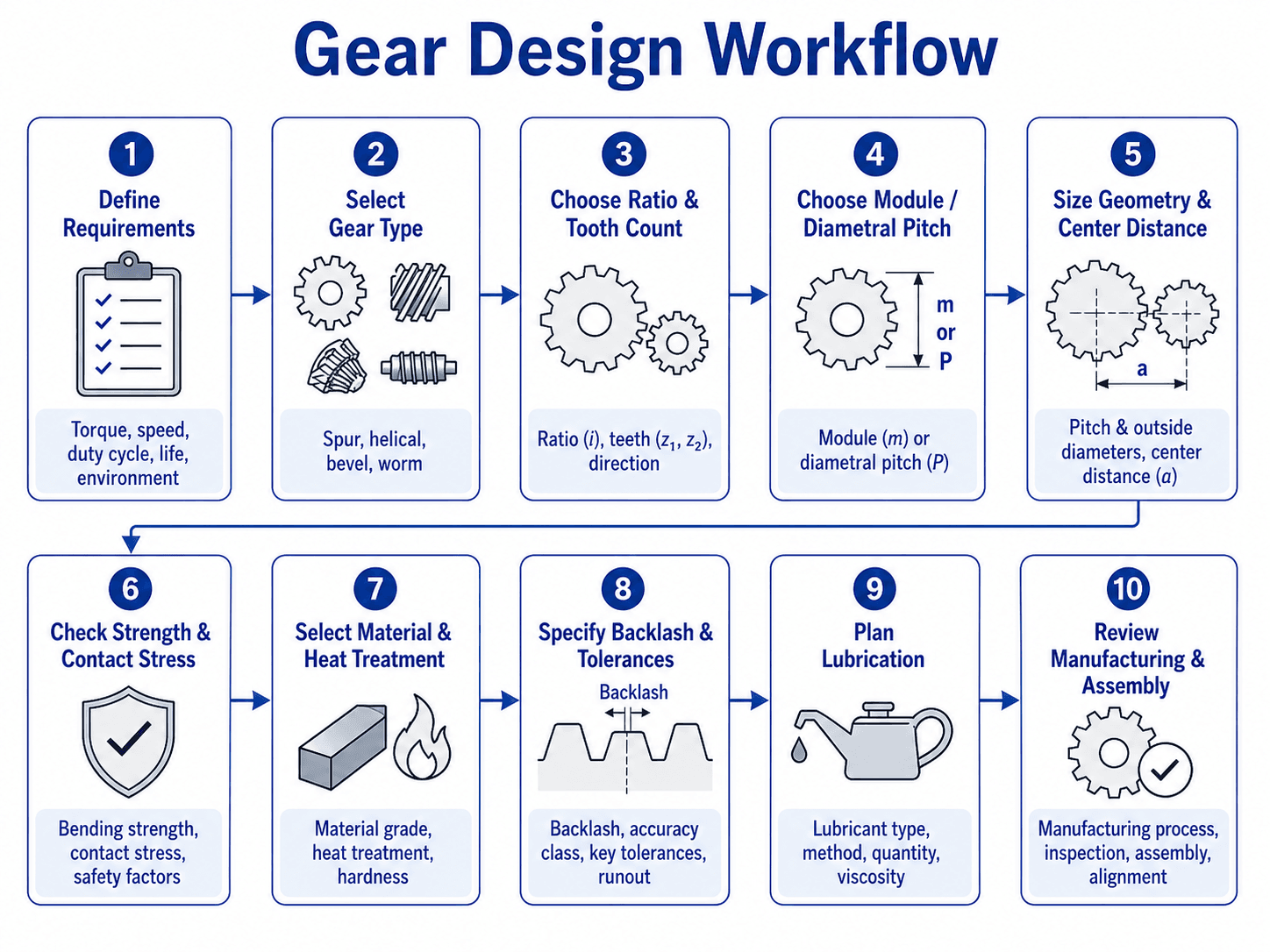
The most important point is sequence. Tooth count and module should come after the torque, speed, ratio, duty cycle, environment, and shaft arrangement are known.
What Is Gear Design?
Gear design is the process of turning a required speed ratio and torque transfer into a physical gear system. It includes gear type selection, gear ratio, tooth count, pitch diameter, module or diametral pitch, pressure angle, face width, material, heat treatment, lubrication, backlash, shaft support, and manufacturing quality.
In mechanical design, gears are not designed in isolation. A gear pair affects shafts, bearings, housings, seals, lubrication systems, noise, vibration, thermal behavior, inspection requirements, and maintenance access. A design that looks correct geometrically may still be unacceptable if the teeth are too weak, the contact stress is too high, the housing is too flexible, or the backlash closes under thermal growth.
Treat gear design as a load-path problem. The torque enters one shaft, becomes tangential force at the pitch circle, creates radial and sometimes axial bearing loads, and exits through the driven gear. If those forces are not carried by the shafts, bearings, and housing, the gear teeth will not stay aligned.
Gear Design vs Gear Selection
Gear design and gear selection are closely related, but they are not the same task. Gear selection usually means choosing a standard catalog gear that matches a required ratio, bore, pitch, material, and load rating. Gear design means defining the tooth geometry, strength, material, heat treatment, tolerance, lubrication, manufacturing method, and inspection requirements for the gear system.
| Task | Typical goal | Engineering risk if skipped |
|---|---|---|
| Catalog gear selection | Choose an available gear with acceptable bore, tooth count, pitch, material, width, and rating. | The gear may fit geometrically but fail if the actual duty cycle, shock load, lubrication, or alignment is worse than the catalog assumption. |
| Custom gear design | Define tooth geometry, material, heat treatment, tolerance, rating, inspection, and manufacturing requirements. | A gear may be expensive or impossible to manufacture consistently if production constraints are ignored. |
| Hybrid design and selection | Calculate loads and geometry first, then select standard gears that satisfy the engineering requirements. | This is common in machine design because it balances reliability, cost, lead time, and availability. |
Gear Design Inputs Engineers Need Before Sizing Teeth
Gear design should begin with requirements, not tooth geometry. The designer needs to know what the gear system must transmit, how long it must operate, how much space is available, and what conditions will change the load. These inputs determine whether a simple spur gear pair is enough or whether the design needs a helical, bevel, worm, planetary, hardened, ground, enclosed, or lubricated system.
| Design input | Why it matters | Engineering implication |
|---|---|---|
| Power, torque, and RPM | These define the transmitted load and pitch-line velocity. | Higher torque usually pushes the design toward larger teeth, wider face width, stronger materials, or multiple reduction stages. |
| Required ratio | The ratio controls output speed and torque multiplication. | Tooth counts must meet the target ratio while avoiding poor geometry, undercutting, excessive size, or impractical center distance. |
| Duty cycle and shock loading | A gear in intermittent light service is different from a continuously loaded gearbox with starts, stops, or impact. | Shock, reversing loads, and long run time increase the need for service factors, fatigue checks, stronger materials, and better lubrication. |
| Shaft arrangement | Parallel, intersecting, and non-parallel shafts require different gear types. | Spur and helical gears suit parallel shafts, bevel gears suit intersecting shafts, and worm gears suit non-parallel right-angle drives. |
| Space and center distance | The available package limits pitch diameter, face width, shaft spacing, and bearing placement. | Compact designs may require higher-strength materials, multi-stage reductions, planetary gears, or tighter tolerance control. |
| Noise, accuracy, and positioning | Gear tooth quality and backlash affect vibration, smoothness, and repeatability. | Low-noise or positioning systems need better alignment, controlled backlash, higher quality gears, and often helical or ground teeth. |
| Environment and lubrication | Temperature, contamination, speed, and accessibility change the lubricant film and wear rate. | Open gears, dirty environments, high temperatures, or high speeds require more careful lubricant selection and maintenance planning. |
What Controls Gear Design?
The controlling variable in gear design is not always the same. Some gearsets are limited by tooth bending strength, others by surface pitting, noise, heat, lubrication, package size, backlash, or manufacturing quality. A good design review identifies which factor is actually controlling before increasing size or material cost.
| Design control | If it increases | What usually changes |
|---|---|---|
| Torque | Tooth load and shaft load increase. | Larger module, wider face width, stronger material, heat treatment, or additional reduction stages may be needed. |
| Speed | Dynamic load, noise, heat, and lubrication demand increase. | Gear quality, balance, lubricant selection, enclosure design, and pitch-line velocity checks become more important. |
| Ratio | Gear size or tooth count difference grows. | Multiple stages, planetary gearing, worm gearing, or alternate packaging may be better than one oversized gear pair. |
| Shock load | Peak tooth stress can exceed steady-state design loads. | Service factors, fatigue margin, material toughness, root strength, and overload protection become more important. |
| Space constraint | Pitch diameters, face width, and bearing spacing are limited. | The design may need stronger materials, tighter tolerances, planetary gearing, or a different power transmission layout. |
| Noise requirement | Small geometry errors become more noticeable. | Helical gears, better tooth quality, improved alignment, controlled backlash, and stiffer housings may be required. |
| Lubrication limit | Film thickness and heat removal become less reliable. | Speed, material, surface finish, enclosure design, lubricant viscosity, and maintenance access may control the design. |
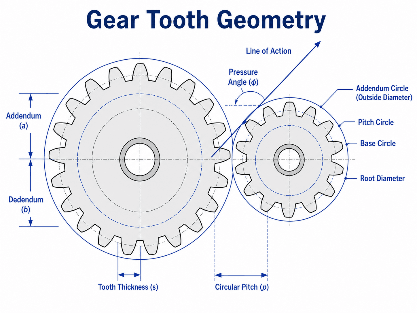
Gear Tooth Geometry Terms That Control the Design
Gear tooth geometry describes how the teeth are shaped and where the gears theoretically contact each other. The pitch circle is the reference circle used for speed ratio and force calculations. The base circle controls involute action. The addendum and dedendum define tooth height above and below the pitch circle. Pressure angle determines the direction of the contact force and strongly affects tooth strength, bearing load, and smoothness.
Module, diametral pitch, and tooth size
Metric gear design commonly uses module \(m\), which is the pitch diameter divided by the number of teeth. U.S. customary gear design commonly uses diametral pitch \(P_d\), which is the number of teeth per inch of pitch diameter. Larger module means larger teeth. Larger diametral pitch means smaller teeth.
Pressure angle and line of action
The pressure angle describes the direction of the normal force between meshing teeth. A larger pressure angle can improve tooth strength but increases radial load on bearings. A smaller pressure angle can reduce radial load but may be more sensitive to tooth strength and interference. This is why gear geometry cannot be separated from shaft and bearing design.
Gear Design Calculations and Core Formulas
First-pass gear design uses simple equations to connect tooth count, pitch diameter, ratio, speed, torque, and transmitted force. These equations are not a complete gear rating method, but they are essential for early layout and sanity checking before detailed stress and durability analysis.
| Formula | Use | Engineering note |
|---|---|---|
| \(i=\frac{N_g}{N_p}\) | Gear ratio for a simple external gear pair. | Relates output speed and torque multiplication before losses. |
| \(d=mN\) | Metric pitch diameter. | Used when gear size is defined by module. |
| \(d=\frac{N}{P_d}\) | Imperial pitch diameter. | Used when gear size is defined by diametral pitch. |
| \(a=\frac{d_p+d_g}{2}\) | Center distance for two external spur gears. | Controls package size, mesh quality, and backlash sensitivity. |
| \(v=\frac{\pi d n}{60}\) | Pitch-line velocity when \(d\) is in meters and \(n\) is RPM. | Higher pitch-line velocity increases noise, heat, dynamic effects, and lubrication demand. |
| \(T=\frac{9550P}{n}\) | Torque from power and speed, using \(P\) in kW and \(n\) in RPM. | Useful when the design starts from motor power instead of measured torque. |
| \(F_t=\frac{2T}{d}\) | Tangential tooth force at the pitch circle. | This is the useful force that transmits torque and drives tooth bending checks. |
| \(F_r=F_t\tan\phi\) | Radial force for a spur gear using pressure angle \(\phi\). | This force pushes gears apart and loads shafts, bearings, and housings. |
| \(F_n=\frac{F_t}{\cos\phi}\) | Normal force at the tooth contact. | Useful for understanding contact loading along the line of action. |
- \(i\) Gear ratio; dimensionless. Used to relate input and output speed.
- \(N_p, N_g\) Number of teeth on the pinion and gear.
- \(m\) Module, usually in millimeters per tooth for metric gears.
- \(P_d\) Diametral pitch, usually teeth per inch of pitch diameter.
- \(d\) Pitch diameter, typically in mm, m, or inches depending on the equation.
- \(a\) Center distance between gear shafts.
- \(T\) Torque at the shaft. Use consistent units with pitch diameter when calculating force.
- \(F_t\) Tangential force at the pitch circle. This drives tooth load and gear reaction forces.
- \(F_r\) Radial separating force created by the pressure angle.
- \(\phi\) Pressure angle, commonly used to resolve gear mesh forces.
Spur, Helical, Bevel, Worm, and Planetary Gear Design Choices
Gear type selection depends on shaft layout, ratio, efficiency, noise, load capacity, space, cost, and manufacturability. Spur gears are simple and common, but they are not always the best choice. Helical gears can run smoother but create axial thrust. Bevel gears change direction between intersecting shafts. Worm gears provide high reduction in a compact right-angle layout but can be less efficient and more heat-sensitive.
| Gear type | Shaft arrangement | Best use case | Main tradeoff | Avoid when |
|---|---|---|---|---|
| Spur gear | Parallel shafts | Simple reduction, moderate speed, easy manufacturing, educational examples. | Simple and efficient, but can be noisier at high speed because tooth engagement is abrupt. | Low noise, high speed, or very smooth torque transfer is critical. |
| Helical gear | Parallel or crossed shafts, depending on configuration | Smoother, quieter operation with better tooth engagement. | Higher contact ratio, but axial thrust must be carried by bearings. | The bearing arrangement cannot handle thrust or axial positioning is weak. |
| Bevel gear | Intersecting shafts | Changing direction between shafts, commonly at right angles. | Compact directional change, but alignment and mounting stiffness are demanding. | The housing cannot hold accurate shaft intersection and alignment. |
| Worm gear | Non-parallel, non-intersecting shafts | High reduction in a compact right-angle drive. | Large reduction is possible, but efficiency, heat, lubrication, and wear require close attention. | High efficiency, low heat, or continuous high-power operation is required without strong thermal control. |
| Planetary gear set | Coaxial input and output | Compact high torque density, load sharing, and multi-stage reductions. | Excellent packaging is possible, but design and manufacturing complexity increase. | Low-cost simple manufacturing or easy visual inspection is the main priority. |
For early ratio decisions, a tool such as the Gear Ratio Calculator can help compare driver teeth, driven teeth, speed ratio, and torque multiplication before the final tooth geometry is selected.
Gear Mesh Forces, Backlash, and Center Distance in Gear Design
Gear teeth do not simply push each other in the direction of rotation. The contact force acts along the line of action and can be resolved into tangential and radial components. The tangential component transmits torque. The radial component pushes the gears apart and loads the shafts, bearings, and housing. Helical, bevel, and worm gears may also create axial force.
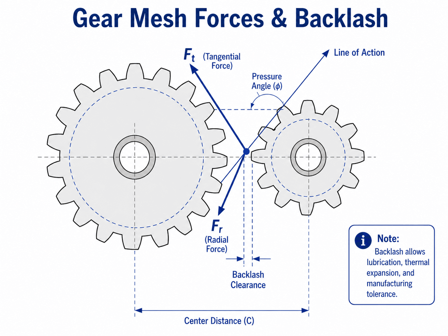
Why backlash is not optional
Backlash is the small clearance between mating tooth flanks. Designers control it because real gears need space for lubrication film, manufacturing tolerance, assembly variation, shaft deflection, housing distortion, and thermal expansion. A zero-backlash gear pair may sound precise, but in many mechanical systems it is more likely to bind, overheat, or wear rapidly unless special anti-backlash geometry is intentionally designed.
Why center distance affects more than packaging
Center distance changes mesh quality, backlash, contact pattern, and load distribution. A housing that flexes under load can effectively change center distance and tooth alignment during operation. This is one reason gearbox design must consider gear teeth, shafts, bearings, and housing stiffness as a connected system.
Gear Materials, Heat Treatment, and Surface Durability
Material selection controls tooth-root strength, surface durability, wear resistance, manufacturability, cost, and noise. A lightly loaded plastic gear may be chosen for quiet motion, while a high-load industrial gear may require alloy steel, case hardening, grinding, and controlled lubrication. The right material depends on the load, speed, environment, service life, and manufacturing method.
| Material or treatment | Where it fits | Design implication |
|---|---|---|
| Low-carbon alloy steel with case hardening | High-load gears that need hard wear-resistant surfaces and tougher cores. | Useful for surface durability and pitting resistance, but heat-treatment distortion and grinding allowance must be considered. |
| Through-hardened medium-carbon steel | Moderate to heavy-duty gears where uniform strength is needed. | Simpler than case hardening but may not provide the same surface durability for severe contact conditions. |
| Cast iron | Lower-speed gears, large gears, and some machinery applications. | Can offer damping and manufacturability benefits, but impact toughness and tooth bending limits must be reviewed. |
| Bronze | Often paired with steel worms in worm gear drives. | Can improve sliding compatibility, but wear, heat, lubricant selection, and efficiency are critical. |
| Engineering plastics | Light-duty, low-noise, low-load, or low-cost mechanisms. | Quiet and corrosion-resistant in some uses, but temperature, creep, wear, moisture, and strength limits matter. |
| Surface finishing and grinding | High-speed, low-noise, high-accuracy, or long-life gearsets. | Improves tooth quality and contact behavior, but increases cost and requires tighter process control. |
A harder surface usually improves wear and pitting resistance, but gear teeth also need a core that can resist shock and bending. The best gear material is not simply the hardest material; it is the material and heat-treatment combination that matches the load, speed, lubricant, manufacturing process, and inspection plan.
Worked Spur Gear Design Example
A simple example shows how early gear design decisions connect. Suppose a motor drives a machine through a spur gear reduction. The motor runs at 1,800 RPM, delivers 2 kW to the pinion, and the design needs roughly a 3:1 speed reduction. The pinion is selected with 20 teeth and the driven gear with 60 teeth.
Step 1: Check the ratio and output speed
The driven gear rotates at one-third of the motor speed, so the output speed is approximately 600 RPM before losses and downstream effects are considered.
Step 2: Estimate input torque
With a 3:1 reduction, the ideal output torque is approximately three times the pinion torque before losses. Real output torque will be lower because of gear mesh friction, bearing losses, lubricant drag, and other inefficiencies.
Step 3: Select a first-pass module
If a first-pass metric module of \(m=3\ \text{mm}\) is selected, the pitch diameters are:
The center distance for the gear pair is:
Step 4: Estimate tangential and radial force
The tangential force at the pinion pitch circle is:
For a 20° pressure angle spur gear, the radial separating force is:
Step 5: Interpret the design
This layout gives the target ratio, estimated output speed, first-pass center distance, tangential tooth load, and radial bearing load. It still does not prove the gears are strong enough. The next checks are bending stress, contact stress, face width, material, heat treatment, service factor, lubrication, backlash, shaft deflection, bearing reactions, and housing stiffness.
If the calculated center distance is too large, the designer can reduce module, split the ratio across multiple stages, use a different gear type, or reconsider the required speed reduction. If the teeth are too weak, the designer may need larger module, wider face width, better material, heat treatment, or a different load-sharing arrangement.
Senior Engineer Gear Design Review Checklist
A useful gear design review checks more than the gear ratio. The goal is to confirm that the tooth geometry, load capacity, material, mounting, lubrication, tolerance, and manufacturing plan all support the same operating requirement.
Requirements → gear type → ratio and tooth count → module or diametral pitch → center distance and face width → tooth bending and contact checks → material and heat treatment → backlash and tolerances → lubrication → shaft, bearing, housing, manufacturing, and inspection review.
| Review check | What to look for | Why it matters |
|---|---|---|
| Requirements are defined | Power, torque, RPM, ratio, duty cycle, life, shock load, operating temperature, and environment are known. | Gear geometry selected without load and duty information is usually guesswork. |
| Gear type matches the shaft layout | Spur or helical for parallel shafts, bevel for intersecting shafts, worm for compact right-angle reduction, planetary for coaxial compact power density. | The wrong gear type can create unnecessary thrust load, poor efficiency, excessive noise, or packaging problems. |
| Tooth count avoids poor geometry | Pinion tooth count, pressure angle, profile, and ratio do not create unacceptable undercut, weak teeth, or poor contact behavior. | The pinion often sees the highest cycle count and is commonly the controlling member in fatigue. |
| Module or diametral pitch is reasonable | Tooth size fits load capacity, center distance, available cutters, face width, and package constraints. | Too small a tooth may fail; too large a tooth may create unnecessary size, cost, inertia, and noise. |
| Face width is not used as a shortcut | Face width is compatible with alignment, shaft stiffness, housing stiffness, and manufacturing quality. | A wider gear does not help if the load is concentrated on one edge due to misalignment. |
| Backlash and tolerance stack-up are specified | Backlash, center distance tolerance, runout, tooth quality, and assembly adjustment are defined. | Uncontrolled backlash causes noise, heat, positioning error, binding, or impact loading. |
| Material and heat treatment match the duty | Material grade, hardness, case depth, surface finish, and wear resistance are appropriate for the load and life. | Tooth geometry alone cannot compensate for poor material or inadequate surface durability. |
| Lubrication is designed, not assumed | Lubricant type, viscosity, delivery method, sump or grease plan, speed, temperature, and contamination control are addressed. | Many gear failures start as lubrication or contamination problems rather than pure strength failures. |
| Shafts, bearings, and housing are checked | Tangential, radial, and axial forces are passed into shaft deflection, bearing reaction, and housing stiffness checks. | Gear teeth cannot run correctly if the support system lets them move out of alignment. |
| Manufacturing and inspection are realistic | Cutting method, grinding, quality grade, runout, surface finish, inspection tools, and assembly process are achievable. | A theoretically good gear design can fail if it cannot be manufactured or inspected to the required quality. |
Practical Gear Design Sanity Checks
Sanity checks help catch unrealistic gear designs before detailed rating work. These checks do not replace formal calculations, but they help identify designs that are likely to be noisy, fragile, difficult to manufacture, or sensitive to field conditions.
| Check | Healthy sign | Red flag |
|---|---|---|
| Pinion tooth count | The pinion has enough teeth to avoid poor tooth form and excessive undercut risk. | Very low tooth count is used only to force a compact ratio. |
| Face width | Face width is proportional to tooth size and supported by shaft and housing stiffness. | A very wide face is used while alignment, deflection, and contact pattern are not checked. |
| Backlash | Backlash is specified, measurable, and compatible with operating temperature and tolerance stack-up. | The design assumes zero backlash without a special anti-backlash mechanism. |
| Contact pattern | Contact is centered and distributed across the intended tooth face. | Contact is concentrated near one edge, indicating misalignment or deflection. |
| Lubrication | Lubricant type, viscosity, delivery method, and maintenance interval match speed, load, and temperature. | Generic grease or oil is assumed without checking temperature, contamination, or pitch-line velocity. |
| Gear quality | Tooth quality and runout requirements match speed, noise, and positioning needs. | A low-cost gear is used in a high-speed or low-noise system without quality review. |
| Support stiffness | Shafts, bearings, and housing keep the gears aligned under load. | The tooth design is checked, but the support structure is treated as perfectly rigid. |
Common Gear Failure Modes and What They Usually Mean
Gear failures are often symptoms of a system problem. A broken tooth may be caused by overload, but it may also be caused by poor load sharing, shaft deflection, misalignment, shock loading, poor heat treatment, or a stress concentration at the root. Good gear design anticipates how the gear will actually fail if the assumptions are wrong.
| Failure mode | Typical sign | Likely design or operating cause |
|---|---|---|
| Bending fatigue | Crack starts near the tooth root and grows until the tooth breaks. | Tooth root stress is too high, face width is too small, material is insufficient, shock loading is underestimated, or the pinion sees too many cycles. |
| Surface pitting | Small pits form on the tooth contact surface. | Contact stress, surface hardness, lubrication film, contamination, or alignment is not adequate for the duty cycle. |
| Scuffing or scoring | Scratched, smeared, or torn-looking tooth surfaces. | Lubrication breaks down because of high speed, high temperature, poor viscosity, inadequate supply, or contamination. |
| Excessive wear | Tooth profile changes, backlash increases, and noise grows over time. | Lubricant contamination, poor material pairing, open gear exposure, poor surface finish, or inadequate hardness. |
| Noise and vibration | Whine, chatter, rattle, or cyclic vibration. | Poor tooth quality, misalignment, incorrect backlash, shaft deflection, resonance, eccentricity, or uneven load sharing. |
| Overheating | High gearbox temperature, lubricant breakdown, discoloration, or odor. | Excess friction, poor lubrication, excessive sliding, high speed, overload, bearing problems, or insufficient heat rejection. |
If a design concern appears to be stress-related, the next step is usually a more complete stress analysis and support-system review. If the issue is recurring wear or fracture, compare it against broader failure modes in mechanical design.
CAD Gear Geometry Is Not a Complete Gear Rating
CAD tools and gear generators are useful for creating tooth geometry, layouts, assemblies, and interference checks. They can help visualize tooth count, pitch diameter, center distance, and packaging. However, a generated gear model does not automatically prove that the gear can survive the required load, speed, temperature, duty cycle, tolerance, and lubrication conditions.
Do not treat a clean involute model as a validated gear design. CAD geometry should still be checked for tooth bending, contact stress, backlash, material, heat treatment, lubrication, shaft and bearing loads, housing stiffness, runout, surface finish, and inspection requirements.
The same warning applies to imported catalog models. A catalog gear may have the right tooth count and bore but still be wrong for the service life, shock load, lubrication method, temperature, or positioning accuracy of the machine.
Engineering Judgment and Field Reality
Real gear systems rarely operate under a perfectly steady load. Motors start and stop, machines jam, shafts deflect, housings heat unevenly, lubricant gets contaminated, and operators sometimes exceed the intended duty cycle. The best gear design accounts for these realities through service factors, material selection, support stiffness, inspection access, and maintenance planning.
The contact pattern tells a story. If the load is concentrated on one edge of the tooth face, increasing face width may not fix the problem. The real issue may be shaft deflection, bearing placement, housing stiffness, gear runout, or assembly misalignment.
Design teams also need to think about manufacturability. A gear that requires tight tolerances, special heat treatment, grinding, inspection, or unusual material may be technically possible but too expensive or slow to produce. This is where design for manufacturing becomes part of the gear design decision, not a separate step after the design is finished.
When This Breaks Down
Simplified gear formulas are useful for first-pass design, but they break down when the gear system is highly loaded, high speed, shock loaded, noisy, safety-critical, thermally sensitive, or tightly packaged. At that point, the designer needs detailed rating methods, tolerance analysis, lubrication review, deflection analysis, and manufacturing quality control.
- High-speed gearsets: Pitch-line velocity, dynamic load, balance, lubricant churning, heat generation, and noise can control the design more than simple tooth geometry.
- Shock-loaded machines: Crushers, presses, conveyors, indexing systems, and start-stop drives can impose peak loads far above nominal motor torque.
- Flexible housings or long shafts: Deflection can move the gears out of alignment and concentrate load on one tooth edge.
- Precision positioning systems: Backlash, torsional stiffness, tooth quality, and repeatability can matter more than maximum torque capacity.
- Poor lubrication environments: Dust, water, temperature, speed, and maintenance access can dominate wear life.
A gear design method that ignores the support structure is incomplete. Even accurately rated teeth can fail early if shaft deflection, bearing clearance, housing flexibility, heat, or assembly error changes the actual tooth contact pattern.
Common Gear Design Mistakes and Practical Checks
Most gear design mistakes come from treating the gear pair as a geometry problem instead of a loaded mechanical system. The following checks help catch common problems before the design reaches prototype or production.
- Reversing driver and driven teeth: This flips the ratio and can produce the wrong output speed or torque expectation.
- Ignoring pinion fatigue: The smaller gear usually rotates more times and can accumulate fatigue cycles faster than the larger gear.
- Using no backlash: Zero clearance can cause binding when tolerances, heat, lubricant film, or shaft deflection are present.
- Oversizing face width without checking alignment: A wide gear face is only useful if the load is distributed across it.
- Forgetting bearing loads: Tangential force transmits torque, but radial and axial forces still need a support path.
- Assuming material solves everything: Better steel or heat treatment does not fix poor lubrication, misalignment, or an undersized shaft.
- Skipping manufacturing review: Tooth quality, runout, surface finish, and heat-treatment distortion can control noise and life.
Before freezing the design, calculate the ratio, pitch diameters, center distance, pitch-line velocity, tangential force, bearing reactions, expected backlash, and contact pattern. Then ask whether manufacturing and inspection can actually hold the assumptions used in the design.
AGMA, Gear Rating, and Design Validation
For learning, layout, and early design decisions, the equations and workflow above are useful. For critical equipment, production gearboxes, safety-sensitive machinery, and formal rating work, engineers typically use recognized gear standards, manufacturer data, and project-specific requirements.
- Motion + Power Manufacturers Alliance / AGMA standards: MPMA and AGMA gear standards and technical resources cover gear-related standards, technical publications, manufacturing quality, performance, and international gear standardization context.
- Project-specific criteria: Owner requirements, equipment duty, reliability targets, noise limits, maintenance intervals, and manufacturing capabilities may control the final gear specification.
- Engineering use: Designers use standards and manufacturer data to move from first-pass geometry into formal bending, contact, material, quality, lubrication, and inspection requirements.
Frequently Asked Questions
The first step in gear design is defining the required power, torque, speed, gear ratio, duty cycle, shaft arrangement, operating environment, and target life. Tooth geometry should not be selected until the load case and motion requirements are clear.
Module is the metric measure of gear tooth size and is equal to pitch diameter divided by tooth count. Diametral pitch is the imperial measure and is equal to tooth count divided by pitch diameter in inches. A higher module means larger teeth, while a higher diametral pitch means smaller teeth.
Backlash provides clearance between mating gear teeth so the gear pair does not bind when manufacturing tolerance, thermal expansion, lubrication film, shaft deflection, and assembly variation are present. Too little backlash can cause heat, noise, and seizure; too much backlash can cause impact, positioning error, and vibration.
Common gear tooth failures include bending fatigue, overload fracture, surface pitting, scoring, scuffing, abrasive wear, and noise or vibration from poor alignment. The root cause is often a combination of load, material, heat treatment, lubrication, tooth geometry, mounting stiffness, and tolerance control.
Simple gear formulas are useful for layout, ratio, first-pass sizing, and learning the relationships between tooth count, pitch diameter, speed, and force. Formal designs for critical equipment should still be checked against applicable AGMA, ISO, manufacturer, or project-specific rating methods.
Summary and Next Steps
Gear design is the process of creating a reliable gear system from speed, torque, ratio, geometry, material, tolerance, lubrication, and manufacturing constraints. The design has to satisfy motion requirements while preventing bending fatigue, pitting, wear, heat, noise, and misalignment problems.
A strong design workflow starts with requirements, selects the right gear type, sizes the ratio and tooth geometry, checks forces and stresses, controls backlash, and verifies that the shafts, bearings, housing, material, lubricant, and manufacturing process all support the same duty cycle.
Where to go next
Continue your learning path with related Turn2Engineering resources.
-
Gear Ratio Calculator
Compare driver teeth, driven teeth, speed ratio, torque ratio, and multi-stage gear behavior.
-
Torque Calculator
Estimate shaft torque from force, lever arm, power, and rotational speed before evaluating gear tooth loads.
-
Horsepower Formula
Review how horsepower relates to torque, RPM, watts, kilowatts, force, and velocity in rotating equipment.