Key Takeaways
- Core idea: Precast concrete structures are assembled from concrete members cast before placement, then transported, lifted, and connected into a complete structural system.
- Engineering use: Engineers use precast systems for buildings, parking structures, bridges, utility structures, industrial facilities, and repeated structural layouts where speed and quality control matter.
- What controls it: Member strength matters, but the final structure is often controlled by connections, bearing, diaphragm action, erection stability, tolerances, and transportation limits.
- Practical check: A good precast design must be buildable before it is beautiful on paper; connection access, crane picks, camber, joint widths, and tolerance stack-up can control the real project.
Table of Contents
Introduction
Precast concrete structures are buildings or infrastructure systems assembled from concrete members that are cast and cured before being placed in their final position. Common members include wall panels, beams, columns, hollow-core slabs, double tees, stairs, piles, and bridge girders. Their performance depends on member strength, connection detailing, load paths, tolerances, handling, and erection sequencing.
Visual Guide to Precast Concrete Structures
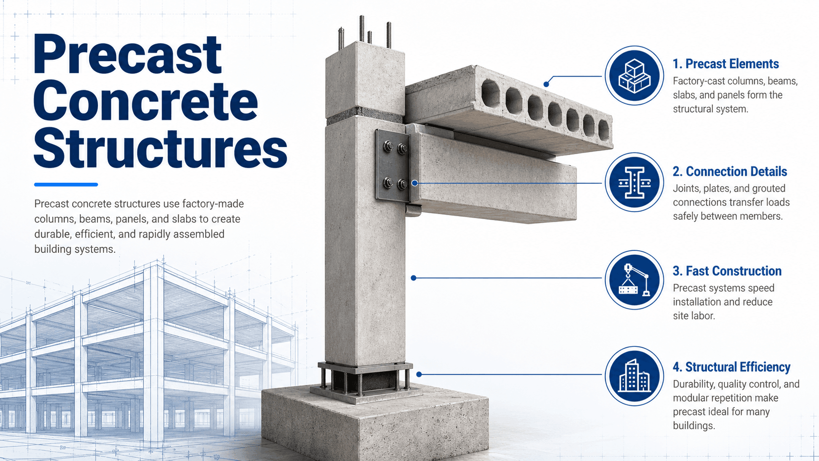
Notice that the individual pieces are not the whole story. The structural behavior depends on how slabs, beams, columns, wall panels, diaphragms, bearing points, and connections work together after erection.
What Are Precast Concrete Structures?
Precast concrete structures are structural systems built from concrete elements that are cast in reusable forms, cured under controlled conditions, stored, transported to the jobsite, and assembled in their final location. Unlike cast-in-place concrete, which is poured and cured where it will remain, precast concrete is manufactured before it becomes part of the completed structure.
In structural engineering, the important word is structures. A precast wall panel, beam, column, hollow-core plank, or double tee may be strong by itself, but the finished structure must still have a continuous load path, stable supports, coordinated tolerances, durable joints, and connections that can transfer the right forces. That is why precast concrete design is as much about system behavior as it is about material strength.
Precast describes when and where the concrete is made. Prestressed describes how internal reinforcement is tensioned to improve span, crack control, and load capacity. A member can be precast, prestressed, both, or neither.
How Precast Concrete Structures Work
A precast structure works by turning individually manufactured components into a stable load-resisting assembly. Floor and roof members collect gravity loads. Beams, bearing walls, and columns transfer those loads downward. Diaphragms, shear walls, cores, frames, and connection groups help transfer wind, seismic, and other lateral forces into the foundation.
Gravity load path
Gravity loads usually begin at the floor or roof surface and move into hollow-core slabs, double tees, solid slabs, or deck systems. Those members bear on beams, ledges, walls, or columns, which transfer reactions to foundations. Bearing length, bearing pad material, ledge geometry, embed plates, and local reinforcement all matter because concentrated reactions can create splitting, spalling, or local crushing if they are not detailed correctly.
Lateral load path
Wind and seismic forces typically move through the floor or roof diaphragm into vertical lateral-force-resisting elements such as precast shear walls, cores, braced frames, or moment-resisting systems. The diaphragm must have enough strength and continuity to drag forces to the resisting elements, and the connections must be able to transfer those forces without relying on accidental friction or unclear load paths.
Temporary stability during erection
Precast components may be stable in the final structure but unstable during erection. Wall panels often require braces, beams may need temporary bearing security, and partially completed diaphragms may not yet provide lateral restraint. A safe precast plan considers the structure at every stage, not just after the last connection is complete.
Main Components of Precast Concrete Structures
Precast systems are selected by span, load, repetition, architectural requirements, transportation limits, plant capability, and erection access. The same project may combine structural precast, architectural precast, prestressed members, cast-in-place topping, steel framing, and field-poured connection zones.
| Precast member | Typical structural role | Practical design note |
|---|---|---|
| Hollow-core slabs | Floor or roof planks spanning between supports | Efficient for repeated spans, but openings, diaphragm reinforcement, topping, and bearing details need early coordination. |
| Double tees | Long-span floor or roof members | Common in parking structures and industrial buildings; camber, flange connections, and drainage slope are important. |
| Precast beams | Horizontal members supporting slabs, tees, or wall loads | Bearing seats, ledges, torsion, connection access, and local reinforcement often control details. |
| Precast columns | Vertical gravity-load members | Splices, base connections, corbels, transportation length, and erection tolerances must be planned carefully. |
| Wall panels | Load-bearing, shear, cladding, insulated, or architectural members | Panels may carry gravity, lateral, thermal, or enclosure loads depending on whether they are structural or nonstructural. |
| Precast stairs and landings | Factory-made egress components | Fit-up, bearing pockets, rail embeds, code dimensions, and finish coordination are common review items. |
| Precast piles and foundations | Deep foundation and support elements | Driving stresses, splice details, geotechnical conditions, and connection to pile caps control performance. |
| Bridge girders and deck panels | Transportation structure components | Prestressing, camber, staged construction, bearing design, and deck continuity are major considerations. |
Types of Precast Concrete Structural Systems
A precast structure may use only a few precast pieces, or it may be a total precast system where the frame, floors, walls, stairs, and façade are largely manufactured off site. The best system depends on the building layout, lateral demand, repetition, construction schedule, architectural finish, site access, and local precast market.
- Total precast buildings: Frames, floors, walls, and stairs are primarily precast, reducing site formwork and speeding erection.
- Precast frame systems: Precast columns and beams support floor or roof members, often with separate lateral-force-resisting elements.
- Precast wall systems: Load-bearing walls, shear walls, insulated panels, or architectural panels provide structure, enclosure, or both.
- Precast floor and roof systems: Hollow-core slabs, double tees, solid slabs, or composite topping systems create horizontal diaphragms and gravity support.
- Hybrid systems: Precast members work with cast-in-place cores, steel frames, masonry walls, or field-poured topping slabs.
- Bridge and infrastructure systems: Precast girders, piles, panels, vaults, culverts, and drainage structures improve construction speed and repeatability.
Precast is usually strongest where repetition is high. A simple repeated bay can be economical and fast; a project with every member unique may lose much of the manufacturing advantage.
Precast Concrete Connections
Connections are the critical transition between separate precast pieces and a complete structure. They transfer load, restrain movement, accommodate tolerances, provide stability, support erection, and protect the long-term durability of the joint. In many projects, the connection details are where constructability problems appear first.
Common connection types
- Bearing connections: Members bear on ledges, corbels, walls, beams, or bearing pads to transfer vertical reactions.
- Welded plate connections: Embedded steel plates are welded in the field to provide shear, tension, or restraint.
- Bolted connections: Bolts and slotted holes can provide adjustability for erection tolerances and future access.
- Dowel and pocket connections: Reinforcing bars, dowels, pockets, and grout transfer forces between members.
- Grouted sleeve connections: Reinforcement is developed through proprietary or detailed sleeve systems, often used in columns or walls.
- Wet joints: Field-placed concrete or grout creates continuity between precast elements.
- Dry joints: Mechanical bearing, welding, bolting, or post-tensioning provides structural action without a large field-poured joint.
- Post-tensioned connections: Tendons compress members together and can improve continuity, serviceability, or seismic behavior when detailed properly.
Why connection behavior matters
The same joint may need to support gravity load, resist lateral force, allow thermal movement, accommodate fabrication tolerance, protect embedded steel from corrosion, and remain accessible to the erector. A detail that looks strong in section can still fail as a project detail if the weld cannot be reached, the slotted plate cannot adjust enough, or the grout pocket cannot be inspected.
Precast Concrete Construction Process
Precast construction starts long before the crane arrives. The engineering design, shop drawings, embeds, tolerances, and erection plan must be coordinated early because field changes after fabrication are expensive and sometimes structurally difficult.
- System selection: The project team chooses whether precast will serve as frame, floor, wall, façade, bridge, utility, or hybrid system.
- Design and coordination: Gravity loads, lateral loads, member sizes, openings, inserts, connection loads, and erection assumptions are established.
- Shop drawings: The precaster develops member drawings, embed locations, lifting points, reinforcement, strand patterns, finishes, and connection details.
- Manufacturing: Forms are prepared, reinforcement and embeds are placed, concrete is cast, and members are cured under controlled conditions.
- Quality control: Dimensions, strength, finishes, embeds, lifting hardware, and tolerances are checked before shipping.
- Storage and transportation: Members are supported and braced to avoid cracking, distortion, or damage before erection.
- Erection: Cranes lift members into place following a planned sequence with temporary bracing where required.
- Final connections: Welding, bolting, grouting, field concrete, topping slabs, joint sealing, and inspections complete the system.
A precast project can lose its schedule advantage if embeds are missed, bearing seats are not ready, anchor bolts are out of tolerance, or the erection sequence forces the crew to install connections out of reach.
What Controls Precast Concrete Design?
Precast concrete design is controlled by more than compressive strength. The final solution must balance structural performance, shipping size, lifting forces, plant production, erection sequence, connection access, dimensional tolerance, serviceability, fire resistance, durability, and cost.
| Factor | Why it matters | Engineering implication |
|---|---|---|
| Load path | Forces must move continuously from slabs and walls to beams, columns, lateral systems, and foundations. | Unclear load paths create risky assumptions at joints, diaphragms, bearing seats, and temporary erection stages. |
| Connection design | Connections transfer gravity, lateral, restraint, and erection loads between separate members. | Connection strength, ductility, access, corrosion protection, and adjustability often control detailing. |
| Tolerances | Members, foundations, embeds, bearing surfaces, and adjacent systems are never perfectly located. | Product, erection, and interfacing tolerances must be coordinated so the structure can actually fit together. |
| Transportation limits | Member length, width, weight, route restrictions, and turning radii limit what can be delivered. | Spans and panel sizes may be controlled by logistics before strength becomes the governing issue. |
| Lifting and handling | Members experience different stresses during stripping, storage, hauling, and crane picks than they do in service. | Lifting inserts, pickup locations, temporary reinforcement, and bracing must be checked for each handling condition. |
| Camber and deflection | Prestressed members may camber upward while long-span members deflect under load. | Floor elevations, drainage, façade alignment, topping thickness, and serviceability can be affected. |
| Durability exposure | Parking decks, bridge elements, coastal sites, and deicing exposure increase corrosion and freeze-thaw concerns. | Concrete cover, joint sealing, drainage, embedded plates, grout pockets, and connection protection need special attention. |
Precast Concrete vs Cast-in-Place Concrete
Precast and cast-in-place concrete are not simply “fast” versus “slow.” They create different design and construction workflows. Precast shifts more work into planning, manufacturing, shipping, and erection, while cast-in-place concrete keeps more flexibility on site through formwork, reinforcement placement, and field-poured continuity.
| Category | Precast concrete | Cast-in-place concrete |
|---|---|---|
| Production | Cast before placement in a plant or controlled casting area | Cast directly in its final location on site |
| Schedule | Can be manufactured while site work continues and erected quickly | Often depends on site formwork, reinforcement, placing, curing, and stripping cycles |
| Quality control | Controlled forms, curing, repeatability, and plant inspection | More dependent on weather, site access, workmanship, and field conditions |
| Structural continuity | Continuity depends heavily on connections and field joints | Can provide more monolithic continuity when detailed and poured correctly |
| Flexibility | Field changes are difficult after fabrication | More adaptable to late field adjustments before placement |
| Equipment | Requires hauling, staging, cranes, rigging, and erection planning | Requires formwork, shoring, concrete placement equipment, and curing time |
| Best fit | Repetition, speed, long spans, factory finish, and constrained jobsite labor | Irregular geometry, field adaptability, monolithic systems, and complex one-off shapes |
Precast Design Review Checklist
Use this checklist as a practical review path when evaluating a precast concrete structure. It is not a substitute for project-specific design, but it helps identify the items that often control coordination, constructability, and structural behavior.
Start with the load path, then review member sizing, then connections, then erection sequence, then tolerances. If any one of those steps is unclear, the structure may be strong in theory but difficult or unsafe to build in practice.
| Check or decision | What to look for | Why it matters |
|---|---|---|
| Confirm the gravity load path | Slabs or tees bearing on beams, walls, ledges, or columns with adequate reaction path to foundations | Precast members often rely on discrete bearing points, so local crushing, splitting, and eccentric reactions must be checked. |
| Confirm the lateral system | Diaphragm continuity, collectors, shear walls, cores, frame action, and connections that transfer wind or seismic forces | A floor system that supports gravity loads may not automatically provide a reliable lateral load path. |
| Review connection access | Weld plates, bolts, grout sleeves, pockets, and inspection points reachable by the erection crew | A structurally adequate connection can still be a poor detail if it cannot be installed, welded, grouted, or inspected properly. |
| Check tolerance stack-up | Product tolerances, foundation layout, embed locations, joint widths, bearing seats, and adjacent façade or MEP systems | Small deviations can accumulate until plates do not reach, panels do not align, or bearing length becomes inadequate. |
| Check handling and erection loads | Pickup points, lifting insert capacity, temporary bracing, storage supports, transport orientation, and partially completed stability | Some precast members see their worst stress before they are in their final design position. |
| Review serviceability | Camber, deflection, vibration, cracking, drainage slope, joint movement, and finish alignment | Even when strength is adequate, serviceability issues can drive repairs, owner complaints, or water intrusion. |
| Coordinate durability details | Joint sealants, drainage paths, cover, exposed plates, corrosion protection, freeze-thaw exposure, and deicing salts | Many long-term precast problems begin at joints, edges, embeds, and moisture traps rather than in the main concrete member. |
Where Precast Concrete Structures Are Used
Precast concrete is widely used where repeated members, controlled production, accelerated schedules, long spans, or durable factory-made components are valuable. The best applications usually have enough repetition to justify the planning and manufacturing effort.
Buildings and parking structures
Parking garages, warehouses, schools, apartments, hotels, dormitories, stadiums, and industrial buildings often use precast beams, columns, wall panels, hollow-core slabs, double tees, and stairs. Parking structures are a common fit because repeated bays, long spans, durability demands, and rapid erection align well with precast production.
Bridges and transportation structures
Precast bridge girders, deck panels, barriers, piles, caps, and segmental components can reduce traffic disruption and improve construction speed. Transportation projects often benefit from precast because work can shift away from the roadway and into a controlled production environment.
Utility and underground structures
Manholes, vaults, culverts, box structures, drainage units, electrical structures, and communication enclosures are commonly precast. These applications benefit from repeatable forms, controlled quality, and rapid installation in trenches or congested utility corridors.
Engineering Judgment and Field Reality
Precast concrete structures reward early decisions. Member sizes, reinforcement, prestressing, embeds, sleeves, openings, connection plates, finishes, joint widths, crane picks, and delivery sequence must be coordinated before fabrication. Late changes that would be simple in cast-in-place construction may require replacement members, field drilling, supplemental steel, or redesign in precast construction.
Experienced engineers also watch for the difference between theoretical continuity and actual field continuity. A diaphragm connection may look continuous on a plan, but if the welded plate is offset, the grout is poorly consolidated, the joint is not cleaned, or the bearing length is reduced by tolerance error, the real load path may be weaker than the drawings imply.
The most expensive precast issues are often not caused by weak concrete. They are caused by missed embeds, inaccessible connections, uncoordinated openings, unexpected camber, poor drainage at joints, or tolerance conflicts between precast, steel, foundations, and façade systems.
When This Breaks Down
A simplified explanation of precast concrete breaks down when it treats the structure as a kit of strong pieces rather than a coordinated structural system. The main risk is assuming that manufactured members automatically create a stable building once they are lifted into place.
- Connection assumptions are vague: If the design does not clearly define connection loads, movements, access, and installation requirements, the load path can become dependent on field judgment.
- Tolerances are not coordinated: Product tolerances, erection tolerances, embed locations, foundation layout, and adjacent construction can conflict if each trade assumes perfect geometry.
- Temporary conditions are ignored: A partially erected structure may not have its final diaphragm, bracing, or load-sharing behavior in place.
- Transportation controls the design: A member that works structurally may be too heavy, too long, too tall, or too difficult to deliver to the project site.
- Water management is poor: Joints, ledges, pockets, and exposed embeds can become durability weak points if drainage and sealing are not considered.
Common Mistakes and Practical Checks
The most common mistakes with precast concrete structures come from treating precast like cast-in-place concrete with a different construction schedule. Precast requires different thinking because the structure is divided into manufactured pieces, and every division creates a joint, tolerance issue, erection question, or connection detail.
- Confusing precast with prestressed: Precast refers to the casting method; prestressed refers to reinforcement behavior.
- Overlooking bearing length: Bearing seats must remain adequate after tolerances, camber, rotation, and erection adjustments are considered.
- Ignoring diaphragm continuity: Floor planks or tees do not automatically create a reliable diaphragm without properly detailed joints and collectors.
- Designing connections without access: Welds, bolts, grout pockets, and inspections must be reachable in the actual erected condition.
- Forgetting erection loads: Lifting, storage, transportation, and temporary bracing can control reinforcement or insert design.
- Leaving openings too late: MEP penetrations, sleeves, embeds, and blockouts should be coordinated before fabrication whenever possible.
Do not judge a precast structure only by the capacity of individual members. The connections, support conditions, erection sequence, and tolerance strategy are what make those members act as a safe structure.
Standards, Manuals, and Design References
Precast concrete design should be developed using the governing project code, contract documents, and recognized precast guidance. The references below are useful for understanding how structural precast systems are typically designed, detailed, manufactured, and erected.
- ACI/PCI CODE-319-25: Provides requirements and commentary specific to structural precast concrete materials, design, and detailing for buildings and applicable nonbuilding structures.
- ACI CODE-318: Provides broader structural concrete design requirements that work with precast-specific provisions where applicable.
- PCI Design Handbook: A major industry reference for precast and prestressed concrete member design, system behavior, connection concepts, and practical detailing.
- PCI tolerance guidance: Helps designers and contractors coordinate product tolerances, erection tolerances, and interfacing tolerances so members can be manufactured and assembled within acceptable limits.
- Project specifications and shop drawings: Define the actual member geometry, embeds, finishes, connection details, erection assumptions, and inspection requirements for the specific project.
Frequently Asked Questions
A precast concrete structure is a building, bridge, utility structure, or other structural system assembled from concrete members that are cast before placement. The members are manufactured in controlled forms, cured, transported, lifted into position, and connected so they work together as a complete load-resisting system.
Common precast concrete members include wall panels, beams, columns, hollow-core slabs, double tees, stairs, piles, bridge girders, utility vaults, and modular units. In structural buildings, slabs and tees usually support floor loads, beams and walls transfer those loads, and columns or bearing walls carry forces down to the foundation.
Precast members are connected with bearing pads, welded plates, bolted plates, dowels, grouted sleeves, pockets, corbels, wet joints, dry joints, and sometimes post-tensioning. The connection type depends on the load path, erection sequence, tolerance needs, durability exposure, and whether the joint must transfer shear, tension, compression, or moment.
The biggest design challenge is making individually fabricated members behave as one coordinated structural system. That requires clear load paths, connection detailing, erection stability, tolerance coordination, camber control, bearing design, diaphragm continuity, and early coordination between the engineer, precaster, erector, architect, and contractor.
Summary and Next Steps
Precast concrete structures are assembled from factory-made or controlled-cast concrete members that become a complete structural system only after they are transported, lifted, aligned, supported, and connected. The main engineering challenge is not simply making strong pieces; it is making those pieces work together through a reliable load path.
Strong precast design requires careful attention to connections, bearing, diaphragms, tolerances, camber, transportation, erection sequence, durability, and field coordination. A well-planned precast system can improve speed and quality, but a poorly coordinated one can create fit-up problems, temporary stability risks, and long-term joint issues.
Where to go next
Continue your learning path with related Turn2Engineering resources.
-
Reinforced Concrete Structures
Learn how concrete and reinforcement work together in structural members and systems.
-
Load Path Analysis
Study how gravity and lateral forces move through structural systems into foundations.
-
Concrete Design
Build a broader foundation in strength, serviceability, durability, and concrete member behavior.