Key Takeaways
- Definition: Concrete design sizes and details concrete members so they resist loads, control cracking, and remain durable.
- Use case: It is used for beams, slabs, columns, walls, footings, cores, parking structures, bridges, and concrete frames.
- Main decision: The designer must balance strength, serviceability, durability, ductility, constructability, and code detailing.
- Outcome: Good concrete design creates a clear load path with practical reinforcement that can actually be built in the field.
Table of Contents
Introduction
In brief: Concrete design proportionally sizes concrete, steel reinforcement, and detailing so structural members safely carry loads and perform over time.
Who it’s for: Students and early-career designers.
For informational purposes only. See Terms and Conditions.
Concrete design is not just selecting a compressive strength. It is the process of turning structural loads, material behavior, detailing rules, and construction realities into safe, serviceable concrete members.
Concrete design infographic
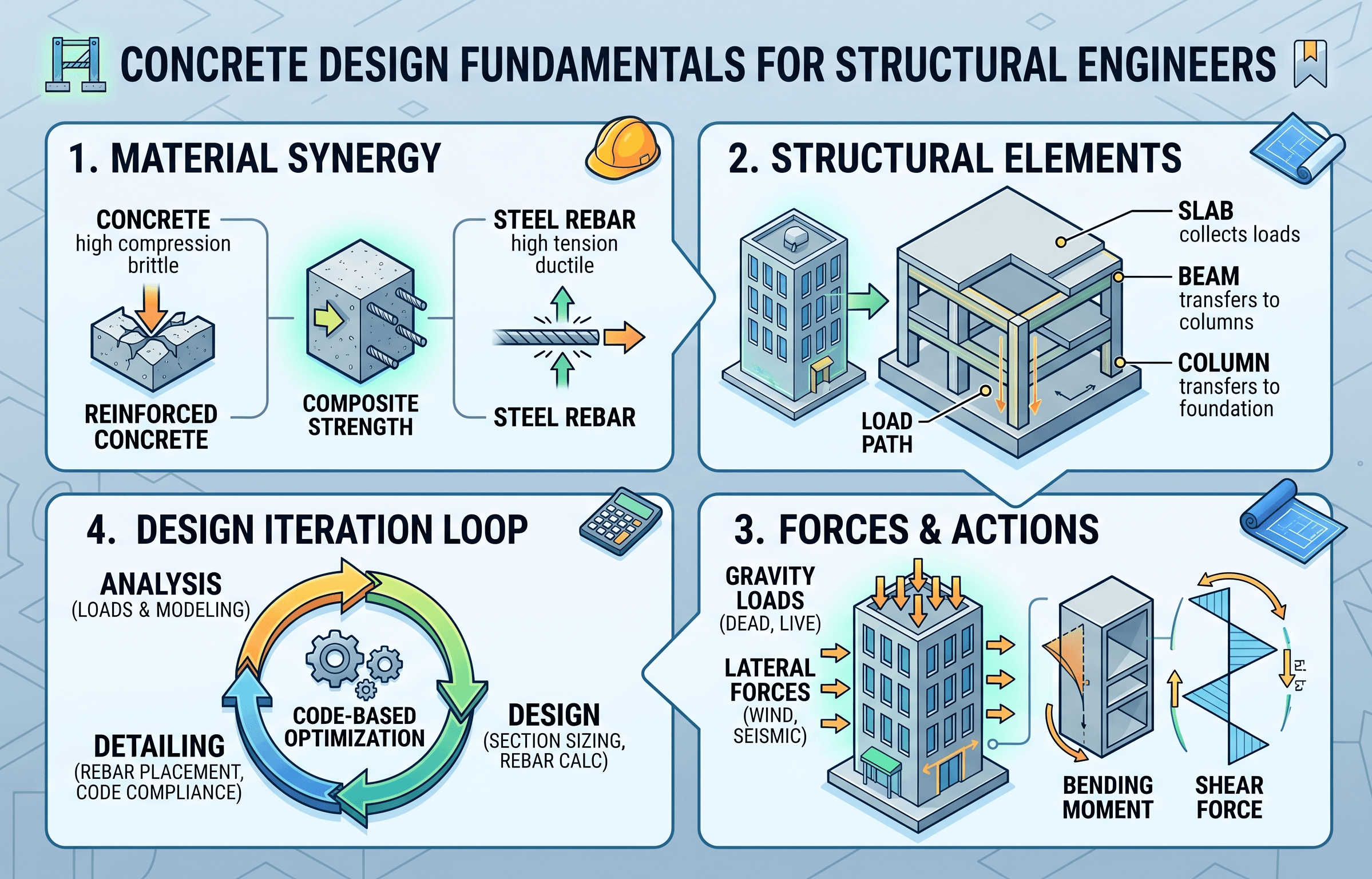
Notice that the design is not controlled by one isolated number. A beam, slab, column, or wall must satisfy strength, serviceability, anchorage, spacing, cover, and exposure requirements at the same time.
What is concrete design?
Concrete design is the structural engineering process of proportioning concrete members and reinforcement so a structure can safely resist gravity loads, lateral loads, environmental exposure, and long-term deformation. In most building and bridge work, this means designing reinforced concrete: concrete carries compression, while steel reinforcement carries tension, controls cracking, and provides ductile behavior.
A concrete member may look simple after it is poured, but the design behind it includes many linked decisions. The engineer must determine the load path, choose the structural system, estimate realistic loads, analyze member forces, select concrete strength, size reinforcement, check serviceability, detail development and splices, and coordinate the design with formwork, construction joints, embed plates, sleeves, tolerances, and inspection requirements.
Concrete design also differs from pure material selection. A high compressive strength does not automatically produce a good structure. A member can have adequate flexural strength and still fail a shear, punching shear, bar development, deflection, crack control, corrosion, or constructability check. Good design keeps those limit states connected from the first layout decision through final placement.
Before refining reinforcement, trace the load path by hand: slab to beam, beam to column or wall, vertical system to foundation, and lateral system to diaphragm and ground.
Core principles, variables, and units
Concrete design is governed by limit states. Strength limit states protect against collapse or loss of load-carrying capacity. Serviceability limit states protect against unacceptable deflection, cracking, vibration, leakage, and appearance problems. Durability requirements protect the structure from corrosion, freeze-thaw damage, sulfate attack, abrasion, heat, moisture movement, and other exposure-driven deterioration.
Material behavior that controls design
Concrete is strong in compression but weak and brittle in tension. Steel reinforcement is placed where tensile stresses develop, such as the bottom of a simply supported beam under gravity load or the top of a continuous slab over an interior support. Once concrete cracks in tension, the reinforcement carries most of that tension while the surrounding concrete still contributes compression, stiffness, bond, and fire protection.
The design also depends on time-dependent behavior. Creep increases long-term deflection under sustained load. Shrinkage creates restraint forces and cracking risk. Temperature changes can widen movement demands. These effects are why concrete design cannot stop at a single ultimate strength calculation.
Key variables and typical ranges
The exact values depend on the governing code, project type, exposure class, and local material availability, but the following variables appear repeatedly in concrete design checks.
- \( f’_c \) Specified concrete compressive strength, commonly expressed in psi or MPa.
- \( f_y \) Yield strength of reinforcing steel, commonly Grade 60 in U.S. building design unless higher grades are specified.
- \( b \) Member width or effective compression width, typically in inches or millimeters.
- \( d \) Effective depth from the extreme compression fiber to the centroid of tension reinforcement.
- \( A_s \) Area of tensile reinforcement provided in a section.
- \( \phi \) Strength reduction factor used to account for uncertainty in strength, failure mode, and ductility.
Always distinguish total member depth from effective depth. Losing effective depth because of cover, bar size, stirrups, or misplaced reinforcement can sharply reduce flexural capacity.
Concrete design workflow
A practical concrete design workflow begins with system behavior, not equations. The engineer first decides how the structure carries gravity and lateral forces, then designs each member so the local details support the global load path.
Define loads and performance criteria → choose the concrete system → analyze forces and reactions → size preliminary members → design flexure, shear, axial, and punching capacity → check deflection and cracking → detail bars, cover, development, splices, and confinement → review constructability and durability.
Step 1: establish the structural system
The system decision determines much of the design. A flat plate slab may simplify formwork but become controlled by punching shear and deflection. A beam-and-slab system may improve stiffness but add depth and coordination issues. A concrete shear wall core may efficiently resist lateral load, but it requires careful boundary element, coupling beam, and foundation coordination.
Step 2: define loads and combinations
Concrete design relies on accurate structural loads. Dead load includes the self-weight of concrete, finishes, partitions, façade systems, mechanical equipment, and permanent fixtures. Live load reflects occupancy and use. Wind and seismic effects may control lateral systems, diaphragms, collectors, walls, and frame elements.
Step 3: analyze forces
The design model must represent how the structure actually behaves. Boundary conditions, continuity, cracking, stiffness modifiers, diaphragm assumptions, column fixity, wall coupling, and foundation support can all change design forces. This is why concrete design is closely tied to structural analysis.
Step 4: design and detail
After analysis, the engineer checks the member for the relevant limit states. Beams often require flexure, shear, development, and deflection checks. Slabs may require flexure, distribution reinforcement, punching shear, crack control, and long-term deflection checks. Columns require axial-moment interaction and confinement detailing. Walls require axial, flexural, shear, boundary, and coupling checks.
How concrete members are designed
Concrete design changes by member type because each member carries force differently. A good structural layout reduces awkward force paths and makes the reinforcement easier to place, inspect, and maintain.
| Member | Main design actions | Common controlling checks | Field-sensitive details |
|---|---|---|---|
| Beams | Flexure and shear | Moment capacity, shear capacity, bar development, deflection | Stirrup spacing, top bar congestion, lap splice locations |
| One-way slabs | Flexure in one primary direction | Minimum thickness, temperature reinforcement, deflection, crack control | Bar spacing, cover, construction joint placement |
| Two-way slabs | Flexure in two directions | Punching shear, column strip moments, deflection | Column-head detailing, drop panels, stud rails, openings |
| Columns | Axial load plus bending | Interaction strength, slenderness, confinement, lap splices | Tie spacing, vertical bar congestion, coupler placement |
| Walls | Axial load, flexure, and shear | Boundary elements, shear friction, overturning, drift compatibility | Boundary congestion, openings, construction sequence |
| Footings | Bearing, flexure, and shear transfer | Soil pressure, one-way shear, punching shear, development | Dowels, cover against soil, top-of-footing elevation |
For a deeper material-focused view, see concrete materials. For a system-level view of frames, slabs, walls, and foundations, see reinforced concrete structures.
Concrete design equations and calculations
Concrete design equations vary by code and member type, but the basic design format compares factored demand against reduced nominal resistance. The following expression captures the design philosophy used across many strength checks.
In this format, \(R_n\) is nominal resistance, \(\phi\) is the strength reduction factor, and \(U\) is the factored load effect or design demand. Depending on the member, \(R_n\) may represent moment strength, shear strength, axial strength, punching shear capacity, bearing strength, or another resistance check.
Flexural strength concept
For a singly reinforced rectangular beam, flexural design is often introduced using the internal compression block and tensile reinforcement force. The simplified nominal moment relationship is:
These equations are useful for understanding behavior, but real design must still satisfy code requirements for strain limits, minimum reinforcement, maximum reinforcement, development length, bar spacing, cover, shear, and serviceability.
Serviceability checks
Strength checks do not guarantee a good floor or wall. Deflection, crack width, vibration, long-term creep, shrinkage, and water tightness can control the final design. A beam may be strong enough at ultimate load yet too flexible for partitions, façade systems, equipment alignment, or user comfort.
Do not optimize only for ultimate strength. Many concrete complaints come from serviceability problems: cracks, ponding, excessive deflection, leakage, or visible movement.
Worked example: reinforced concrete beam concept
Consider a simply supported reinforced concrete beam carrying gravity load from a floor system. The beam span, tributary area, and loads are first used to determine factored bending moment and shear. The designer then selects a trial width and depth, checks flexural capacity, checks shear capacity, and adjusts reinforcement and stirrups until the design is safe, serviceable, and buildable.
Example assumptions
- Beam action is controlled primarily by positive bending at midspan.
- Concrete compression strength is specified as \( f’_c \).
- Longitudinal tension reinforcement is placed near the bottom face.
- Shear reinforcement is provided using closed stirrups.
- Cover, bar spacing, development length, and support detailing are checked after the strength estimate.
Design reasoning
The first question is not “how many bars fit?” but “what force path is the beam part of?” If the slab frames into the beam continuously, negative moment may govern at supports. If an opening interrupts the slab, torsion may appear. If the beam supports a transfer load, shear and anchorage may govern. If the member is shallow, deflection may control before strength does.
Once the governing demand is known, the engineer estimates the steel area needed for flexure, checks whether the neutral axis and strain condition produce ductile behavior, verifies shear strength, then confirms the bars can be developed before their force is needed. A design that passes the moment equation but cannot physically develop the bars at the support is not acceptable.
If increasing bar area creates congestion, it may be better to increase beam depth, revise the framing layout, use bundled bars carefully, change bar grade, or reduce demand through a cleaner load path.
Engineering judgment and field reality
Concrete design is especially sensitive to construction reality because the final member is formed, reinforced, placed, consolidated, cured, and inspected in the field. Unlike a fabricated steel member, much of the final structural quality depends on placement conditions and sequencing. Bar cages that look acceptable in a calculation sheet can become difficult to place if hooks, ties, couplers, embeds, sleeves, and congestion are not considered early.
Experienced engineers look for details that protect design intent during construction. Can workers place and vibrate concrete around congested reinforcement? Is there enough clear spacing for aggregate to pass? Are top bars supported so they do not sink? Are dowels aligned with walls or columns above? Are construction joints located where shear and moment transfer can be handled? Are openings coordinated before reinforcing drawings are released?
The most elegant reinforcement layout is useless if it cannot be placed, inspected, consolidated, and finished without displacing bars or leaving voids.
Design tradeoffs
Concrete design frequently involves tradeoffs between member depth, reinforcement quantity, schedule, formwork complexity, carbon impact, and long-term durability. A deeper beam may reduce steel demand and deflection, but it can interfere with ceiling space and mechanical routing. A thinner slab may save concrete volume, but it may increase deflection risk, require more reinforcement, or trigger punching shear upgrades. Higher-strength concrete can reduce column size, but it may increase quality control demands and change stiffness assumptions.
When this breaks down
Concrete design breaks down when the design model stops representing the real structure. This can happen when supports are assumed fixed but behave flexibly, when slab openings disrupt load paths, when creep and shrinkage are ignored, when reinforcement is misplaced, when construction joints are poorly located, or when durability exposure is more severe than assumed.
It also breaks down when a member is pushed outside the intent of simplified design assumptions. Deep beams, corbels, disturbed regions, transfer girders, anchorage zones, pile caps, brackets, coupling beams, and discontinuity regions often require strut-and-tie modeling or specialized code provisions rather than ordinary beam theory.
Existing structures add another layer of uncertainty. The designer may not know the actual reinforcement, concrete strength, chloride exposure, previous repairs, cracking history, or hidden deterioration. In those cases, investigation, testing, conservative assumptions, and structural inspections become essential.
Common pitfalls and engineering checks
Many concrete design errors are not advanced math errors. They are coordination errors, assumption errors, detailing errors, and load-path errors. The following checks help catch problems before they become expensive field changes or long-term performance issues.
- Check that loads are complete, including self-weight, façade, partitions, equipment, soil, fluid, temperature, wind, seismic, and construction loads where applicable.
- Verify that the load path is continuous through slabs, beams, columns, walls, diaphragms, collectors, foundations, and supporting soil.
- Confirm that reinforcement fits with required cover, clear spacing, bar bends, hooks, couplers, inserts, sleeves, and construction tolerances.
- Check shear and punching shear early, especially at flat plates, transfer members, footings, and heavily loaded supports.
- Review deflection and cracking under service loads, not just factored strength combinations.
- Coordinate durability requirements with exposure, cover, water-cement ratio, curing, coatings, and joint detailing.
- Confirm development length and lap splices in the actual region where force must transfer.
| Check | Why it matters | Typical warning sign | Better design response |
|---|---|---|---|
| Bar development | Reinforcement must transfer force into concrete | Bars terminate near high-moment regions | Extend bars, add hooks, revise supports, or use couplers |
| Punching shear | Flat slabs can fail around columns | Thin slab with heavy column reaction | Add depth, drop panel, capital, shear reinforcement, or change layout |
| Deflection | Serviceability can control floor performance | Long shallow spans with sustained load | Increase depth, add beams, change system, or refine long-term analysis |
| Crack control | Cracks affect durability, leakage, and appearance | Large bar spacing or restraint cracking | Use distributed reinforcement, joints, curing, and exposure-appropriate cover |
| Constructability | Unbuildable details create field risk | Congested bars at joints and supports | Simplify layout, adjust member sizes, coordinate embeds, or sequence placement |
Treating bar schedules as an afterthought often leads to congestion, missing development, inadequate cover, and reinforcement that cannot be inspected or placed correctly.
Visualizing the concrete load path
A useful way to visualize concrete design is to follow compression and tension through the structure. In a typical floor, load moves from the slab into beams or directly into columns and walls. Compression zones form in the concrete, tension zones are controlled by steel reinforcement, and shear transfer keeps the internal force couple stable.
At supports, the force path often becomes more complex. Top reinforcement may resist negative moment, stirrups may control diagonal tension, column bars may require confinement, and slabs may need punching shear reinforcement. This is why concrete drawings must communicate not only bar sizes, but also where those bars are needed and how forces transfer through joints.
For page speed and clarity, this section remains text-only; the main instructional infographic above is the single in-body image for this resource.
Relevant standards and design references
Concrete design should always be performed using the governing code adopted by the project jurisdiction, along with project specifications and owner requirements. The references below are commonly relevant to structural concrete design.
- ACI 318, Building Code Requirements for Structural Concrete: The primary U.S. reference for reinforced concrete member strength, serviceability, detailing, development, durability, and structural systems in buildings.
- ASCE/SEI 7, Minimum Design Loads and Associated Criteria for Buildings and Other Structures: Used to determine gravity, wind, seismic, snow, rain, flood, and load combination requirements that feed concrete member design.
- International Building Code: Establishes adopted structural design requirements, references material codes, and connects local building regulation to concrete design practice.
- ACI 301, Specifications for Structural Concrete: Supports construction-phase requirements such as materials, placement, finishing, curing, tolerances, and quality acceptance.
- PCI and AASHTO references: Commonly used where precast concrete, prestressed concrete, transportation structures, or bridge-related design controls the project.
Frequently asked questions
Concrete design is the process of sizing and detailing concrete members and reinforcement so beams, slabs, columns, walls, and foundations safely resist loads, control cracking and deflection, and remain durable in their exposure environment.
The controlling check depends on the member and system, but common controls include flexure, shear, punching shear, axial-moment interaction, deflection, crack control, bar development, reinforcement spacing, cover, and durability exposure.
Concrete design is the broader workflow for concrete structural systems, while reinforced concrete design specifically focuses on members where steel reinforcement is embedded to resist tension, control cracking, and improve ductility.
Concrete performs well in compression but poorly in tension, so steel reinforcement is added where tensile stresses develop to carry tension, control crack widths, provide ductility, and help the member behave predictably after cracking.
Advanced analysis is often needed for transfer members, deep beams, disturbed regions, high-rise lateral systems, seismic detailing, unusual openings, staged construction, prestressed systems, nonlinear behavior, or existing structures with uncertain material conditions.
Summary and next steps
Concrete design is the structural engineering process that turns loads, material behavior, member geometry, reinforcement, serviceability, and durability into a safe and buildable structure. The key is not memorizing one equation, but understanding how compression, tension, shear, anchorage, cracking, deflection, and field placement interact.
In practice, the best concrete designs are clear, coordinated, and inspectable. They follow a reliable load path, satisfy code strength and serviceability checks, provide enough cover and development, avoid unnecessary congestion, and reflect how concrete will actually be formed, placed, cured, and maintained.
Where to go next
Continue your learning path with these structural engineering topics.
-
Study reinforced concrete structures
Learn how reinforced concrete frames, slabs, walls, and foundations behave as complete structural systems.
-
Review concrete materials
Understand how mix design, cement, aggregates, admixtures, curing, shrinkage, and durability affect structural performance.
-
Learn steel reinforcement detailing
Go deeper into bar selection, spacing, cover, corrosion protection, anchorage, and constructible reinforcement layouts.