Key Takeaways
- Core idea: Differential protection compares current entering and leaving a CT-defined protected zone.
- Engineering use: It provides fast, selective protection for transformers, buses, generators, motors, and transmission lines.
- What controls it: CT location, CT polarity, CT ratio, transformer compensation, restraint logic, and relay settings control performance.
- Practical check: A dependable scheme trips for internal faults while staying secure for external faults, CT saturation, inrush, switching, and wiring errors.
Table of Contents
Introduction
Differential protection is a power system relay method that compares current entering and leaving a protected zone. When the difference is large enough to indicate an internal fault, the relay trips the associated breaker or breakers. It is one of the fastest and most selective ways to protect critical equipment because it responds to faults inside a defined zone instead of simply reacting to high current anywhere in the system.
How Differential Protection Sees the Protected Zone
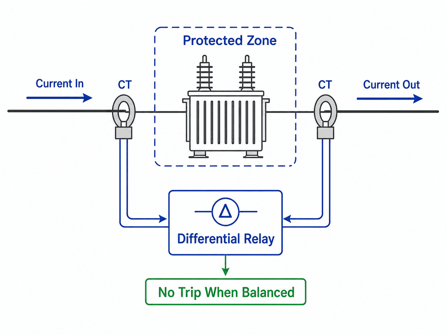
The dashed boundary is the most important part of the diagram. Everything between the CTs is inside the differential zone, and the relay decision depends on whether the compensated current measurements around that zone balance.
What Is Differential Protection?
Differential protection is a unit protection scheme. Instead of waiting for a current value to exceed a general pickup setting, it compares measurements from two or more current transformers around one protected piece of equipment or one protected zone. If the currents do not balance after ratio, phase, and relay compensation are applied, the relay interprets the difference as current leaving the normal path through a fault.
The protected zone may be a transformer, busbar, generator winding, motor, cable, or transmission line section. Because the relay is looking at the difference between currents around a defined zone, it can be very fast and selective. A fault inside the zone should trip immediately, while a fault outside the zone should pass through without tripping the differential element.
Differential protection is only as accurate as the zone definition. CT placement, CT polarity, wiring, ratio compensation, and relay logic decide whether the relay is comparing the correct currents.
How Differential Protection Works
In normal operation, load current flows through the protected equipment. The current entering the zone and the current leaving the zone should match when viewed from the relay’s reference direction. During an internal fault, part of the current flows into the fault inside the zone, so the incoming and outgoing CT measurements no longer balance.
CTs Define the Zone
Current transformers are placed at the boundaries of the equipment or circuit section being protected. Everything between those CTs is inside the differential zone. Anything outside those CTs is normally outside the zone, even if the external fault creates very high current through the protected equipment.
The Relay Compares Compensated Currents
The relay receives secondary current signals from the CTs. In a beginner explanation, it checks whether current in equals current out. In real protection schemes, the relay compares compensated current quantities that account for CT ratio, polarity, reference direction, transformer phase shift, zero-sequence treatment, restraint current, harmonic content, communication timing, and operating thresholds.
The differential current \(I_{\text{diff}}\) is the measured imbalance seen by the relay. A simple differential element may trip when this value exceeds a pickup setting, but practical relays often use percentage restraint so that small measurement errors do not cause a trip during heavy load or high external fault current.
- \(I_{\text{in}}\) Current measured entering the protected zone after CT scaling and relay reference direction are applied.
- \(I_{\text{out}}\) Current measured leaving the protected zone after compensation.
- \(I_{\text{diff}}\) The operating or differential current that indicates imbalance inside the protected zone.
Internal Faults vs External Faults
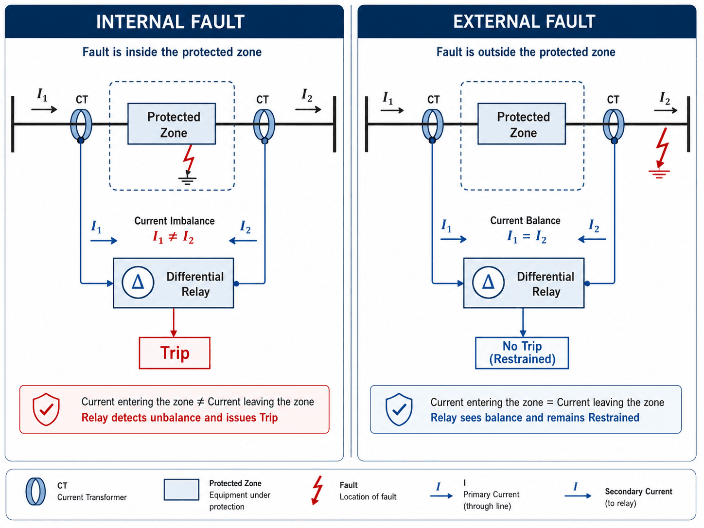
Differential protection is powerful because it separates internal and external faults by location, not just magnitude. An internal fault is inside the CT-defined zone and should trip. An external fault may create very high through-current, but the relay should remain restrained if the CT measurements still balance.
Internal Fault
An internal fault occurs between the CTs. Current may feed the fault from multiple directions, and the relay sees a mismatch between current entering and leaving the protected zone. This is the condition differential protection is designed to detect quickly.
External Fault
An external fault occurs outside the zone. Current can be very high, but it should pass through the protected zone and leave through the opposite CT. If the CTs reproduce current accurately and the relay settings are appropriate, the differential element should not trip.
ANSI 87 Device Numbers and Common Differential Functions
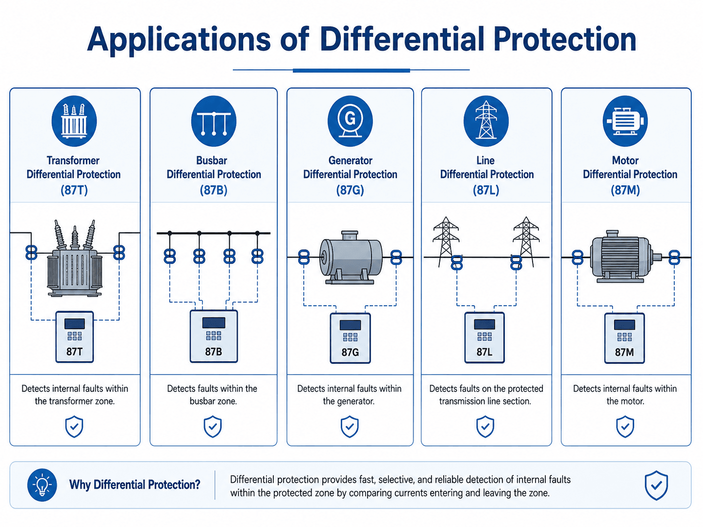
Differential protection is commonly identified by ANSI device number 87. The suffix after 87 usually indicates the protected equipment or application. These labels are useful when reading one-line diagrams, relay panels, protection settings, and trip logic drawings.
| Device label | Common meaning | Typical protected zone |
|---|---|---|
| 87 | Differential protection | General current differential element for a defined protected zone |
| 87T | Transformer differential protection | Transformer windings, bushings, and terminal zone between CTs |
| 87B | Bus differential protection | Substation bus section and connected breaker zone |
| 87G | Generator differential protection | Generator stator winding zone |
| 87L | Line differential protection | Transmission line, cable, or feeder section between terminals |
| 87M | Motor differential protection | Motor winding and terminal lead zone |
Where Differential Protection Is Used
Differential protection is usually applied where equipment is expensive, fault energy is high, or fast selective isolation is important. The exact relay logic changes by equipment type, but the core comparison of currents around a protected zone remains the same.
| Application | Typical device label | What the relay is protecting | Key engineering concern |
|---|---|---|---|
| Transformer differential | 87T | Transformer windings and internal transformer zone | CT ratio matching, phase shift compensation, inrush restraint, and zero-sequence treatment |
| Busbar differential | 87B | Substation bus sections and connected breaker zones | CT locations, bus switching, breaker arrangement, and external fault stability |
| Generator differential | 87G | Generator stator winding zone | Fast clearing of winding faults while remaining secure for external system faults |
| Line differential | 87L | Transmission line or cable section between terminals | Communications, synchronization, charging current, and multi-terminal behavior |
| Motor differential | 87M | Motor winding zone and terminal leads | CT location, starting current behavior, and coordination with motor protection functions |
Transformer Differential Protection
Transformer differential protection is one of the most common and most nuanced applications. A transformer changes voltage and current magnitude, and many transformer connections also shift phase angle. The relay must compensate for ratio and phase shift so that normal load and external faults do not appear as internal faults.
Transformer energization also creates magnetizing inrush current, which may be large and unbalanced even though there is no internal fault. Modern 87T schemes commonly use harmonic restraint, harmonic blocking, or waveform-based logic to improve security during energization while still tripping quickly for winding faults.
Bus Differential Protection
Bus differential protection protects a bus section rather than a single piece of equipment. This can be challenging because bus configuration may change as breakers and disconnects are operated. A bus differential scheme must understand which circuits are connected to the bus and which CTs belong in the active differential zone.
High-impedance and low-impedance bus differential schemes are both used in practice. High-impedance schemes are simple and secure when CTs are well matched, while low-impedance schemes are common in modern numerical relays because they can handle more flexible bus arrangements and multiple input currents.
Line Differential Protection
Line differential protection compares currents at the local and remote terminals of a line or cable. Unlike transformer or bus differential protection, the relay usually needs a communication channel so that each terminal can compare local current with remote-end current.
Because 87L protection depends on remote measurements, timing, channel status, data alignment, and backup protection become part of the engineering design. A secure scheme must handle channel delay, lost communication, CT performance, charging current, and multi-terminal line behavior.
Differential Protection vs Overcurrent Protection
Differential and overcurrent protection both respond to abnormal current, but they answer different engineering questions. Overcurrent protection asks whether current is too high. Differential protection asks whether current is unbalanced across a protected zone.
| Comparison point | Differential protection | Overcurrent protection |
|---|---|---|
| Primary decision | Is there an internal current imbalance inside the protected zone? | Has current exceeded a pickup value for a selected time or curve? |
| Typical speed | Very fast for in-zone faults because it is highly selective | Often time-delayed for coordination with downstream devices |
| Zone selectivity | Defined by CT boundaries | Defined by pickup, time-current coordination, and system impedance |
| Best use | Critical equipment protection such as transformers, buses, generators, motors, and lines | Feeder, equipment, and backup protection for overloads and short circuits |
| Main weakness | More sensitive to CT errors, wiring, compensation, and scheme design | May be slower or less selective for close-in high-value equipment faults |
In practical protection design, differential protection is often the primary protection for critical equipment, while overcurrent protection is used for feeder protection, backup protection, and coordination with downstream devices.
Percentage Differential Protection and Relay Slope
A real current differential relay should not trip for every small mismatch. CTs have ratio error, CTs can saturate, transformer current quantities require compensation, and heavy external faults can produce small spill current into the differential element. Percentage differential protection, also called biased differential protection, improves security by adding restraint.
The restraint current \(I_{\text{rest}}\) represents the amount of through-current seen by the protected zone. As through-current increases, the relay typically requires a larger differential current before tripping. This makes the scheme more secure for CT saturation, ratio error, and high external fault current.
This equation is a simplified way to understand slope or bias restraint, not a substitute for a relay manual. \(I_{\text{pickup}}\) is the minimum differential pickup, \(S\) represents the slope or bias, and \(I_{\text{rest}}\) represents restraint. Many modern relays use multiple slopes so the relay can be sensitive at low current while remaining secure during high through-fault current.
A percentage differential element is trying to balance dependability and security: trip fast for a true internal fault, but do not trip for external faults, CT mismatch, or CT saturation.
Simple Differential Current Example
Suppose a relay measures 500 A entering one side of a protected transformer zone and 492 A leaving the other side after compensation. The simplified differential current is:
That 8 A difference may simply reflect CT and measurement error under load, not an internal fault. During a true internal fault, the mismatch is usually much larger and supported by the relay’s operate/restraint characteristic, harmonic logic, event records, and protection settings.
Now assume the relay sees very high through-current during an external fault. Even a small percentage of CT error can create differential current. That is why restrained differential logic is used: the relay should become more secure as through-current increases, while still remaining sensitive to real faults inside the zone.
Differential Protection Commissioning and Misoperation Checklist
Differential protection failures are often not caused by the concept itself. They are caused by incorrect CT connections, poor compensation, untested breaker outputs, CT saturation, inrush conditions, or a protected zone that does not match the actual equipment arrangement.
Start with the one-line and CT locations, confirm the protected zone, verify CT ratios and polarity, review relay compensation, test external-fault stability, then verify that the correct breakers trip for an internal-zone fault.
| Protection check | What to look for | Why it matters |
|---|---|---|
| CT polarity | Confirm CT secondary polarity and relay reference direction match the scheme drawing. | Reversed polarity can make normal load or external faults appear as internal differential current. |
| CT ratio and compensation | Check CT ratios, relay scaling, transformer ratio, and vector group compensation. | Incorrect scaling can create false imbalance even when primary currents are correct. |
| Protected zone boundaries | Confirm the CTs actually surround the intended transformer, bus, generator, motor, or line section. | A missed CT location can leave equipment unprotected or cause the wrong breakers to trip. |
| External fault stability | Review through-fault records, commissioning tests, or relay test results for restraint behavior. | The relay must remain secure for faults outside the zone, even when current is high. |
| Transformer inrush logic | Verify harmonic restraint or blocking is configured where transformer energization can occur. | Magnetizing inrush can produce high differential current without an internal transformer fault. |
| Breaker trip outputs | Confirm the relay trips all breakers needed to isolate the protected zone. | Correct detection is not enough if the wrong breaker logic leaves the fault energized. |
| Secondary injection testing | Test relay inputs, pickup behavior, restraint behavior, and trip contacts using controlled secondary currents. | Bench and field testing help confirm that the relay logic matches the intended protection design. |
| Trip matrix verification | Check which breakers, lockouts, alarms, and interlocks operate for each differential element. | A correct relay decision still fails if the wrong device trips or the correct breaker does not trip. |
| Line differential communications | Check communication channel status, timing, addressing, and remote terminal data quality. | 87L schemes depend on reliable remote-end current measurement and timing logic. |
Engineering Judgment and Field Reality
Textbook diagrams often show two perfect CTs and one simple relay. Actual power systems are messier. CTs saturate differently, transformer banks shift phase angles, breakers define zones in non-obvious ways, and relay event records must be interpreted against the one-line diagram and the actual field wiring.
Experienced protection engineers do not only ask whether the relay saw differential current. They ask whether the CTs were wired correctly, whether the fault was inside the zone, whether the relay should have restrained for through-current, whether oscillography supports the trip decision, and whether the trip isolated exactly the intended equipment.
A differential relay event should be reviewed with the CT circuits, breaker status, fault location, relay oscillography, equipment configuration, and switching state. The same measured current pattern can mean different things depending on zone boundaries.
When This Breaks Down
Differential protection breaks down when the relay comparison no longer represents the actual current balance around the protected equipment. This can happen because of measurement error, incorrect scheme setup, changing system configuration, or conditions that look like internal fault current even when no internal fault exists.
- CT saturation: A high external fault can saturate one CT more than another, creating false spill current into the relay.
- Transformer energization: Magnetizing inrush may appear as differential current unless the relay uses appropriate restraint or blocking.
- Incorrect compensation: Transformer phase shift, ratio, or zero-sequence compensation errors can create false imbalance.
- Bus configuration changes: Bus differential schemes can fail if disconnect status or breaker configuration is not represented correctly.
- Communication issues: Line current differential schemes can lose security or dependability if remote-end data is delayed, missing, or mismatched.
- Relay or breaker failure: Differential protection still needs backup protection if a relay, trip circuit, breaker, CT circuit, or communication path fails.
These limitations do not make differential protection weak. They explain why commissioning, testing, and protection review are just as important as the relay function itself.
Common Mistakes and Practical Checks
The most common misunderstanding is treating differential protection as a simple “current in does not equal current out” rule without understanding compensation and restraint. That simple rule explains the principle, but real relay application requires careful treatment of current direction, transformer behavior, CT performance, and breaker logic.
- Ignoring CT polarity: A reversed CT can turn a secure scheme into one that trips during load or external faults.
- Assuming all current mismatch is a fault: Small differential current may be normal under load or external-fault conditions.
- Forgetting transformer phase shift: Transformer winding connections can shift current phase angles and require relay compensation.
- Missing the breaker zone: A protected zone must align with actual breaker trip capability, not just the equipment nameplate.
- Using differential protection without backup: Differential protection is primary zone protection, but backup protection is still needed for relay, breaker, CT, and communication failures.
Do not judge a differential protection scheme from the relay settings alone. Review the one-line diagram, CT circuits, breaker trip matrix, transformer vector group, event records, and field wiring together.
Standards, References, and Design Context
Differential protection is an engineering application topic, so the final scheme normally depends on utility standards, owner requirements, equipment data, relay manuals, CT performance, and commissioning practices. For line current differential schemes, communication and synchronization details become especially important.
- IEEE C37.243: IEEE guide for digital line current differential protection covers practical line current differential schemes using digital communications, including operating principles, synchronization, channel requirements, CT requirements, backup considerations, testing, and troubleshooting.
- Project-specific criteria: Utility standards, protection philosophy documents, equipment specifications, and commissioning procedures often control how the relay is selected, wired, set, tested, and maintained.
- Engineering use: References and standards help engineers move from the basic current-comparison concept to a secure, dependable, testable protection scheme.
Frequently Asked Questions
Differential protection is a relay scheme that compares measured current entering and leaving a protected zone. If the difference indicates an internal fault, the relay trips the associated breaker or breakers to isolate that zone.
ANSI 87 is the device function number commonly used for differential protection. Common variations include 87T for transformer differential, 87B for bus differential, 87G for generator differential, 87L for line differential, and 87M for motor differential.
For an external fault, the through-current entering and leaving the protected zone should still balance after CT scaling and compensation. A properly applied differential relay restrains instead of tripping because the fault is outside the CT-defined zone.
Percentage differential protection, also called biased differential protection, compares differential current against restraint current. It improves security by requiring more operating current as through-current increases, which helps prevent false trips during external faults and CT saturation.
Common causes include CT polarity errors, incorrect CT ratios, wiring mistakes, CT saturation during through-faults, transformer inrush, missing phase-shift compensation, communication problems in line differential schemes, and incorrect relay settings.
Summary and Next Steps
Differential protection is a selective relay method that protects a defined zone by comparing current entering and leaving that zone. When the current balance breaks in a way that indicates an internal fault, the relay trips the necessary breakers to isolate the affected equipment.
The main engineering challenge is not the basic comparison itself. It is making sure the CTs, compensation, restraint logic, breaker outputs, communication channels, event review, and commissioning tests all support the intended zone of protection.
Where to go next
Continue your learning path with related Turn2Engineering power systems resources.
-
Protective Relays
Learn how relays detect abnormal power system conditions and initiate breaker trips.
-
Short-Circuit Analysis
Review how available fault current affects protection, equipment ratings, and system studies.
-
Transmission Line Protection
Explore how distance, overcurrent, pilot, and line differential schemes protect transmission circuits.