Key Takeaways
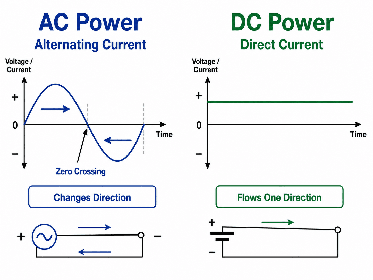
- Core idea: AC power reverses polarity periodically, while DC power normally maintains fixed polarity for a given connection.
- Engineering use: AC dominates conventional utility grids and building distribution, while DC is central to batteries, solar PV, electronics, EV charging, data centers, and HVDC links.
- What controls it: The best choice depends on voltage transformation, distance, load type, conversion equipment, protection, cost, and whether the system is AC-native or DC-native.
- Practical check: Do not assume DC is always more efficient or AC is always simpler; the full source-to-load path determines the real answer.
Table of Contents
Introduction
AC vs DC power systems compares two ways electrical energy is generated, converted, transmitted, stored, and delivered to loads. AC power alternates polarity and is widely used in utility grids because transformers make voltage conversion practical. DC power maintains fixed polarity and is common in batteries, solar PV, electronics, EV charging, and HVDC transmission.
AC and DC Power at a Glance
The first difference is waveform behavior, but the engineering difference is larger. A power system includes the source, conductors, transformers or converters, protection equipment, controls, grounding, and loads—not just the current waveform.
What Are AC vs DC Power Systems?
An AC power system uses alternating current, where voltage and current reverse direction periodically. In most utility systems this happens at a fixed frequency, commonly 60 Hz in the United States and 50 Hz in many other parts of the world. AC systems are especially useful where voltage must be stepped up for transmission and stepped down for distribution.
A DC power system uses direct current, where polarity remains fixed during normal operation for a given connection. DC is natural for electrochemical storage, solar PV modules, electronic circuits, LED drivers, telecommunications equipment, EV battery systems, and DC links inside power electronic equipment. Modern power systems often combine both, using converters to move power between AC and DC sections.
AC vs DC Power Systems Comparison Table
The main difference between AC and DC power systems is not only current direction. The choice affects voltage conversion, equipment ratings, protection design, power quality, storage integration, transmission economics, and how easily the system connects to the existing grid.
| Comparison point | AC power systems | DC power systems |
|---|---|---|
| Current direction | Voltage and current alternate direction periodically | Voltage polarity and current direction normally remain fixed for a given connection |
| Frequency | Operates at a system frequency such as 50 Hz or 60 Hz | No steady-state frequency in the same sense as sinusoidal AC |
| Voltage transformation | Transformers provide simple, mature, efficient voltage step-up and step-down | Power electronic converters are usually required to change voltage level |
| Common grid role | Generation, transmission, distribution, and building service | HVDC links, battery systems, PV arrays, DC buses, electronics, and converter-connected systems |
| Reactive power and power factor | Real power, reactive power, voltage support, and power factor must be considered | Steady-state DC does not have sinusoidal reactive power, but converters can still affect the AC side |
| Storage compatibility | Storage usually connects through inverter or charger equipment | Batteries and many storage devices are naturally DC |
| Protection difficulty | AC current crosses zero, which helps interruption and arc extinction | DC faults can be harder to interrupt because there is no natural current zero crossing |
| Transmission use | Mature and widely used for interconnected grids and conventional transmission corridors | Useful for long-distance HVDC, submarine cables, asynchronous grid ties, and controllable bulk transfer |
| Typical conversion equipment | Transformers, AC switchgear, relays, and AC breakers | Rectifiers, inverters, DC/DC converters, DC breakers, fuses, and converter controls |
| Main limitation | Reactive power, synchronization, line effects, and AC network power-flow constraints | Converter cost, converter losses, DC protection, polarity management, and specialized equipment ratings |
Which Is Better: AC or DC Power?
AC is usually better for conventional utility grids, transformers, motors, building distribution, and most existing power infrastructure. DC is usually better for batteries, solar PV output, electronics, EV charging, DC buses, and some long-distance transmission links. Hybrid AC/DC systems are common whenever DC-native sources or storage must connect to AC buildings or the utility grid.
| Use case | Better fit | Why |
|---|---|---|
| Residential wall outlet | AC | Utility distribution and building wiring are standardized around AC service |
| Battery storage | DC internally | Batteries store and release energy through electrochemical DC behavior |
| Solar panel output | DC at the module | PV cells produce DC that is often inverted to AC for building or grid use |
| Long-distance controllable transmission | HVDC in selected projects | DC links can support long-distance transfer, cable routes, and asynchronous AC interconnections |
| Motors and industrial distribution | Usually AC, often three-phase | Three-phase AC supports efficient motors, switchgear, transformers, and mature protection practices |
| Electronics and LED loads | DC internally | Electronic circuits operate on DC rails even when the building supplies AC input |
The best system is the one that minimizes unnecessary conversion while still using reliable equipment, safe protection, maintainable controls, and a practical interconnection path.
Why Most Utility Grids Use AC
Most large utility grids use AC because AC voltage can be transformed efficiently. A generator may produce power at one voltage, a transformer can step it up to a much higher transmission voltage, and another transformer can step it down for distribution and customer use. That voltage flexibility is one of the biggest reasons AC became the backbone of modern power systems.
These two relationships explain the practical advantage of high-voltage transmission. For the same real power \(P\), increasing voltage \(V\) reduces current \(I\). Because conductor heating losses scale with \(I^2R\), reducing current can greatly reduce losses and conductor heating. AC transformers made that voltage step-up and step-down practical at grid scale.
Three-phase AC supports efficient bulk power transfer
Utility power is usually delivered as three-phase AC because it provides smoother power transfer, efficient motor operation, and practical conductor use. Three-phase systems are also easier to analyze, protect, and operate in conventional transmission and distribution networks.
Reactive power and power factor matter in AC systems
AC systems carry both real power and reactive power. Inductive and capacitive equipment can shift current relative to voltage, which affects power factor, voltage regulation, conductor loading, and system stability. DC steady-state systems do not have sinusoidal reactive power in the same way, although converters connected to AC systems can still control or disturb AC-side reactive power.
AC voltage is usually specified as RMS voltage
AC nameplate voltage is normally given as root-mean-square voltage, not peak waveform voltage. For a sinusoidal waveform, the peak voltage is higher than the RMS value.
This distinction matters for insulation, clearances, surge protection, equipment ratings, and comparing AC and DC voltage levels. A 120 V AC circuit has a peak voltage of about 170 V under an ideal sinusoidal waveform.
AC equipment is mature and standardized
Transformers, breakers, relays, switchgear, distribution panels, motors, and utility protection practices have been developed around AC infrastructure for more than a century. That equipment base matters because a power system is not only a waveform; it is an entire ecosystem of hardware, standards, maintenance practices, and operating procedures. For deeper grid behavior, see voltage regulation and load flow analysis.
Where DC Power Systems Are Used Today
DC systems are not limited to small electronics. Many modern energy systems are DC-native at some point in the chain. Solar modules produce DC, batteries store and deliver DC, many electronic loads operate internally on DC, and HVDC links can move large amounts of power over long distances before converting back to AC.
| Application | Why DC appears | Engineering implication |
|---|---|---|
| Solar PV arrays | PV modules produce DC voltage and current | Grid-connected systems need inverters, protection, disconnects, and voltage-window review |
| Battery energy storage | Batteries charge and discharge as DC devices | Battery systems require DC protection, converters, thermal management, controls, and coordination with AC interconnection equipment |
| EV charging | Vehicle batteries are DC; fast chargers deliver controlled DC to the battery | Power electronics, cooling, grounding, and grid impact become major design issues |
| Data centers and electronics | Servers, processors, LED drivers, and controls use internal DC rails | Repeated AC/DC conversion can affect efficiency, redundancy, harmonics, and backup power architecture |
| HVDC transmission | DC can transfer bulk power over long distances or between asynchronous AC systems | Converter stations, control strategy, protection, and project economics control feasibility |
AC-coupled vs DC-coupled solar and battery systems
Solar-plus-storage projects often use either AC-coupled or DC-coupled architecture. In an AC-coupled system, solar and battery equipment connect on the AC side through separate inverters or inverter paths. In a DC-coupled system, the solar array and battery share a DC bus before power is inverted to AC.
AC coupling can be attractive for retrofits because it often connects into existing AC infrastructure more easily. DC coupling can reduce some conversion steps and may be useful when solar charging, battery charging, and inverter dispatch are designed as one coordinated system. The correct choice depends on backup requirements, inverter compatibility, clipping, efficiency, interconnection limits, and operating modes.
When reviewing an AC/DC system, mark every conversion point. Each inverter, rectifier, DC/DC converter, and transformer adds cost, losses, controls, protection requirements, heat, and possible failure modes.
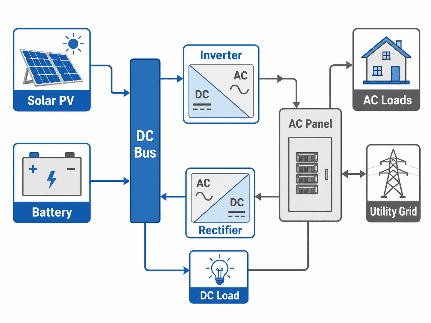
AC/DC Conversion: Inverters, Rectifiers, and DC Buses
Most real power systems are not purely AC or purely DC. They are connected through conversion equipment. A rectifier converts AC to DC. An inverter converts DC to AC. A DC/DC converter changes one DC voltage level to another. A DC bus collects or distributes DC power within equipment, battery systems, solar systems, drives, or hybrid microgrids.
Inverters make DC sources usable on AC systems
Solar PV, batteries, and many power electronic resources connect to AC systems through inverters. The inverter controls voltage, current, frequency response, power factor behavior, and protection response depending on the system design and interconnection requirements.
Rectifiers make AC sources usable for DC loads
Rectifiers are common in battery chargers, DC power supplies, variable frequency drives, telecom systems, and EV charging equipment. They allow AC service to feed DC loads, but they also introduce converter losses, heat, harmonics, and equipment-specific protection needs.
Converters can affect power quality
Power electronics can introduce harmonics, switching noise, voltage ripple, and control interactions if they are not filtered, rated, and coordinated correctly. This is why AC/DC conversion is not only an efficiency issue; it is also a power quality, thermal, protection, and controls issue.
DC buses simplify some systems but complicate protection
A DC bus can reduce unnecessary conversion where sources and loads are already DC-native. However, DC bus protection must be carefully designed because DC faults can rise quickly and may sustain arcs without the natural current zero crossing that helps AC interruption.
AC vs HVDC Transmission Link: Converter Stations at Both Ends
Transmission is where the AC vs DC comparison becomes most project-specific. Conventional AC transmission is mature, transformer-friendly, and widely integrated into existing grids. HVDC transmission can be attractive for long-distance bulk transfer, submarine cables, underground links, renewable energy corridors, and connections between asynchronous AC systems.
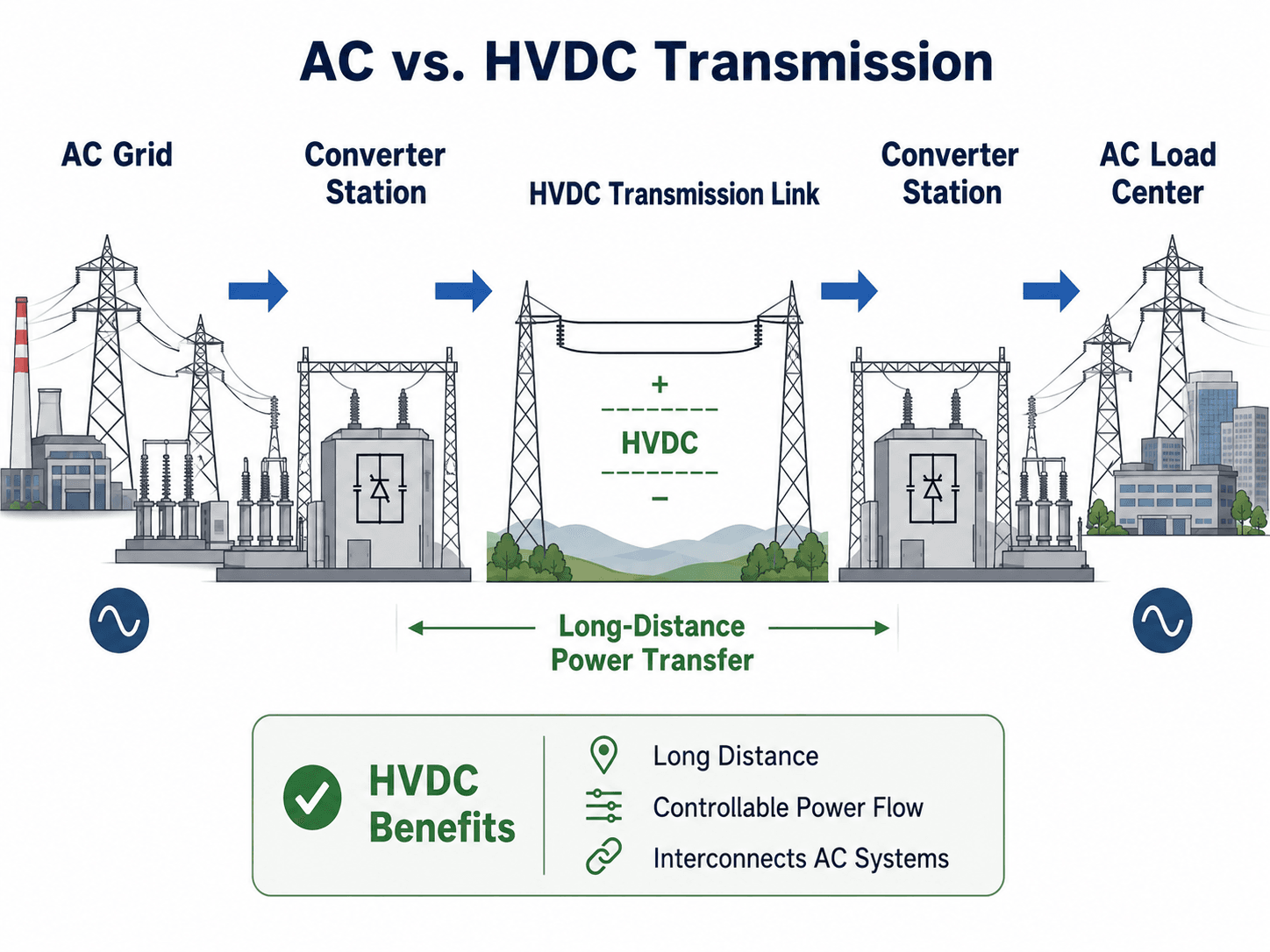
HVDC is usually a transmission solution, not a replacement for local AC distribution. Most HVDC projects still begin and end in AC systems, with one converter station changing AC to DC and another converter station changing DC back to AC.
| Transmission condition | AC transmission often fits when… | HVDC may fit when… |
|---|---|---|
| Distance | The route is shorter or already integrated into an AC network | The route is long enough that DC line benefits can offset converter station cost |
| Grid connection | Both ends are in the same synchronized AC system | The project must connect asynchronous AC systems or control scheduled power exchange |
| Route type | Overhead AC lines are practical and right-of-way constraints are manageable | Submarine, underground, constrained corridor, or remote renewable transfer favors a DC link |
| Control needs | Power flow can be managed through the surrounding AC network | Precise controllable transfer is a major project objective |
| Project complexity | Lower terminal complexity is important | Converter station cost and controls are justified by the transmission objective |
AC, DC, or Hybrid: Practical Selection Matrix
The right answer is rarely “AC is better” or “DC is better.” Engineers usually choose the architecture that minimizes conversion steps, keeps protection practical, meets interconnection requirements, and matches the source and load behavior.
Start with the source and load. If both are AC-native, AC distribution is usually the simplest path. If both are DC-native, a DC bus may reduce conversion. If the system touches the utility grid, buildings, motors, PV, batteries, or EV charging, expect a hybrid architecture and review every conversion point.
| Design question | AC usually fits when… | DC usually fits when… | Hybrid often fits when… |
|---|---|---|---|
| What type of load dominates? | Building distribution, motors, transformers, and conventional grid loads dominate | Electronics, LED systems, battery loads, or DC equipment dominate | Buildings include both AC service and large DC-native subsystems |
| Is energy storage central? | Storage is small or connected through standard AC equipment | Batteries directly serve DC loads or a DC bus | Battery storage supports an AC facility or grid interconnection through inverters |
| Is voltage conversion frequent? | Transformer-based voltage changes are the main requirement | Power electronic conversion is already required and acceptable | Transformers and converters are both needed at different parts of the system |
| Is long-distance transmission involved? | The project uses conventional AC transmission or local grid expansion | Long-distance HVDC, submarine cable, or asynchronous interconnection is justified | AC systems are connected at both ends through a DC transmission link |
| How difficult is protection? | Standard AC breakers, relays, and coordination practices apply | DC protection equipment is available and designed for the fault behavior | Separate AC and DC protection zones are clearly defined and coordinated |
Protection, Safety, and Fault Behavior
Protection is one of the most important practical differences between AC and DC systems. AC faults are still dangerous, but AC current naturally passes through zero twice per cycle. That zero crossing helps breakers and switching devices interrupt current and extinguish arcs. DC does not have that natural zero crossing, so DC interruption often requires equipment designed specifically for DC fault behavior.
Safety depends on voltage, available fault current, exposure path, clearing time, arc behavior, grounding method, and equipment ratings—not simply whether the system is AC or DC. For related fault concepts, see fault analysis and short circuit analysis.
| Protection issue | AC system concern | DC system concern |
|---|---|---|
| Fault interruption | Breakers and relays are mature, but fault current can be very high | No natural current zero makes interruption and arc extinction more difficult |
| Grounding | Grounding affects touch voltage, protective device operation, and fault-current return paths | DC grounding choices affect polarity, insulation stress, fault detection, and personnel safety |
| Arcing | AC arcs can be severe but are helped by current zero crossings | DC arcs may be more persistent and require DC-rated disconnects and breakers |
| Coordination | Protective relay coordination is well-established in utility and building systems | Converter controls, semiconductor limits, fuses, breakers, and fault detection must be coordinated carefully |
Never use an AC-rated switch, breaker, or disconnect as if it is automatically acceptable for DC. DC voltage, fault current, polarity, interrupting rating, and arc behavior must be checked against the actual equipment rating.
Engineering Judgment and Field Reality
Textbook AC vs DC comparisons often stop at waveform shape, but real systems are judged by operating reliability, maintainability, protection, available equipment, controls, and cost. A solar-plus-storage facility, for example, may have DC PV strings, a DC battery system, inverter output, AC collection equipment, transformers, protection relays, and utility interconnection requirements all inside one project boundary.
The best architecture is often the one that avoids unnecessary conversions while still using proven protection and interconnection equipment. A system that looks efficient on a block diagram can become harder to operate if converters, grounding, isolation, and fault response are not reviewed together.
What experienced reviewers look for
- Clear separation between AC protection zones and DC protection zones.
- Converter ratings that match the expected voltage, current, thermal, and fault duty.
- Equipment ratings that explicitly cover AC or DC service as applied.
- Grounding and bonding paths that support safe operation and fault detection.
- Conversion losses and heat rejection included in efficiency and equipment layout decisions.
- Operating modes reviewed for charging, discharging, grid export, backup operation, islanding, and maintenance.
When This Breaks Down
The simple AC vs DC comparison breaks down when it ignores system boundaries. A DC source may serve an AC load through an inverter. An AC feeder may feed DC loads through rectifiers. A long-distance DC line may still begin and end in AC systems. The practical question is not just “AC or DC?” but where conversion happens and what each conversion does to losses, controls, protection, and cost.
- Ignoring converters: Efficiency claims are incomplete if inverter, rectifier, transformer, and DC/DC converter losses are excluded.
- Ignoring protection: A DC architecture may look clean electrically but require more specialized interruption and fault detection equipment.
- Ignoring reactive power: AC system loading, voltage regulation, and power factor can control equipment sizing and system behavior.
- Ignoring existing infrastructure: Existing utility and building systems are usually AC, so DC-native equipment still needs an interconnection strategy.
- Ignoring operating modes: Battery charging, battery discharging, islanding, grid export, emergency backup, and maintenance states can all change current paths.
Common Misconceptions and Practical Checks
Many AC vs DC explanations are technically correct but incomplete. The biggest mistakes come from treating one system as universally superior instead of matching the power architecture to the source, load, distance, and protection requirements.
| Misconception | Better engineering interpretation | Practical check |
|---|---|---|
| DC is always more efficient | DC can be more efficient in some DC-native or HVDC applications, but converter losses and equipment cost matter | Compare the complete path from source to load, including every conversion stage |
| AC is outdated | AC remains dominant because transformers, three-phase systems, and utility infrastructure are highly practical | Check whether the project actually benefits from replacing AC equipment with DC equipment |
| Solar buildings are DC systems | PV modules are DC, but most buildings still distribute AC after inverter conversion | Identify whether the PV output is used on a DC bus, through string inverters, or through microinverters |
| HVDC replaces AC transmission everywhere | HVDC is valuable for specific long-distance, cable, asynchronous, or controllable-flow cases | Compare converter station cost, route length, power transfer objective, and system integration requirements |
| DC systems are automatically safer | Both AC and DC can be hazardous depending on voltage, current, arc behavior, clearing time, and exposure path | Review equipment ratings, disconnecting means, grounding, arc risk, and protection coordination |
Useful References and Design Context
AC and DC power systems are broad engineering topics, so the most useful reference is one that connects the basic AC/DC distinction to real grid infrastructure and HVDC applications. Project-specific design still depends on equipment ratings, utility interconnection requirements, applicable electrical codes, and owner criteria.
- U.S. Department of Energy: DOE discussion of HVDC transmission benefits and grid interconnection use cases explains why HVDC can be useful for long-distance transfer, controllable power flow, and interconnecting asynchronous AC systems.
- Project-specific criteria: Equipment ratings, protection studies, grounding method, local electrical code requirements, utility interconnection rules, and manufacturer instructions can control the final design.
- Engineering use: Designers use these references to decide where AC infrastructure remains appropriate, where DC links or buses add value, and how converters and protection should be integrated.
Frequently Asked Questions
Most utility grids are primarily AC because AC voltage can be transformed efficiently for generation, transmission, and distribution. DC is still used in important parts of the modern grid, including HVDC transmission links, solar PV systems, battery storage, electronics, and converter-based equipment.
Homes use AC because the utility distribution system is standardized around AC service, transformers, protection equipment, and building wiring. Many devices then convert that AC input to DC internally because electronics, batteries, LED drivers, computers, and phone chargers operate on DC circuits.
DC can be more efficient in some applications, especially DC-native systems and long-distance HVDC transmission, but it is not automatically better. Converter losses, converter station cost, protection complexity, voltage level, distance, load type, and equipment availability all affect the final system choice.
Solar PV modules produce DC power. In most grid-connected buildings, an inverter converts that DC power into AC so it can serve AC loads, connect to the utility grid, and operate with standard building distribution equipment.
Summary and Next Steps
AC vs DC power systems is a comparison between two electrical architectures, not just two waveform shapes. AC remains dominant in utility grids because voltage transformation, three-phase operation, and standardized infrastructure make it practical for generation, transmission, distribution, and building service.
DC is essential wherever energy storage, solar PV, electronics, EV charging, DC buses, and HVDC transmission are involved. The practical engineering decision depends on the complete source-to-load path, including conversion points, protection, grounding, losses, cost, power quality, and maintainability.
Where to go next
Continue your learning path with related Turn2Engineering resources.
-
Power Transmission
Learn how bulk electrical power is moved over long distances and why voltage level, conductor losses, and transmission architecture matter.
-
Power Quality
Understand how harmonics, voltage disturbances, and converter-based equipment can affect AC and hybrid AC/DC systems.
-
Grounding Techniques
Review grounding, bonding, fault-current paths, and safety concepts that affect both AC and DC power systems.