Key Takeaways
- Definition: Euler’s Formula predicts the elastic critical buckling load of a slender column from stiffness, cross-section resistance to bending, and effective length.
- Main use: Engineers use it for quick buckling checks, trend analysis, and understanding how end restraint and slenderness change axial capacity.
- Watch for: It assumes an ideal slender column with elastic behavior, small initial imperfections, and centric compression.
- Outcome: After this page, you should be able to read the formula, define the variables, rearrange it, and judge when it is or is not trustworthy.
Table of Contents
Pinned column before and after elastic buckling
Euler’s Formula predicts the elastic critical buckling load of a slender column from its stiffness, length, and end restraint.
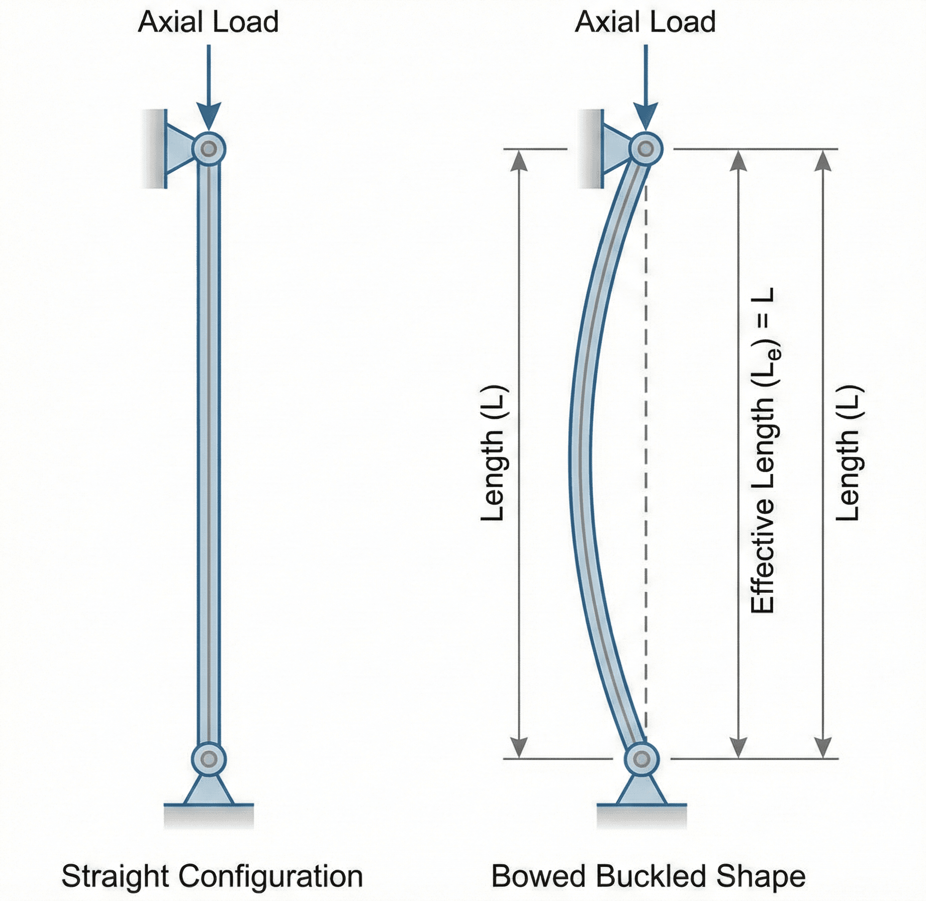
Notice that the column can fail by lateral deflection even while the material is still elastic. That is why effective length, end restraint, and least-axis stiffness matter so much in Euler buckling checks.
What is Euler’s Formula?
In structural engineering, Euler’s Formula is the classic elastic buckling equation for slender columns in axial compression. It estimates the load at which a perfectly straight member becomes unstable and suddenly bows sideways rather than simply shortening under load.
That distinction matters. A column may buckle long before the compressive stress reaches the material’s crushing or yield strength. For slender members, stability often controls before material strength does.
Engineers use Euler’s Formula to understand column behavior, compare design options, check trends during preliminary design, and build intuition for how unsupported length, end restraint, and section stiffness affect buckling capacity.
The Euler’s Formula equation
The most common structural form of Euler’s Formula is shown below. It predicts the elastic critical load for buckling about the weak axis of the member.
Physically, this equation says that buckling capacity rises with elastic stiffness \(E\), rises with flexural stiffness \(I\), and drops rapidly as effective length increases. Because \((KL)\) is squared, slenderness has a very strong influence on the result.
This alternate form introduces the radius of gyration \(r\) and makes the role of slenderness ratio clearer. It is often the better form when comparing columns with different cross sections or when connecting the buckling load to compressive stress.
Variables and units
Euler buckling is unforgiving about units. The formula is simple, but only if the modulus, section property, and length units are consistent from start to finish.
- \(P_{cr}\) Critical buckling load. This is the theoretical axial load at which elastic instability begins.
- \(E\) Modulus of elasticity of the material, such as ksi, psi, MPa, or Pa.
- \(I\) Area moment of inertia about the buckling axis. Use the least-axis value when buckling can occur about either principal axis.
- \(K\) Effective length factor that reflects end restraint. It converts actual unsupported length into effective buckling length.
- \(L\) Unsupported length of the column between points of lateral support.
- \(r\) Radius of gyration, defined as \(r = \sqrt{I/A}\), used in slenderness checks.
If \(E\) is in ksi, \(I\) is in in\(^4\), and \(L\) is in inches, then \(P_{cr}\) comes out in kips. Do not mix feet and inches inside the same expression.
If a small increase in unsupported length causes a large drop in predicted capacity, that is expected. Euler capacity falls with the square of effective length.
| Variable | Meaning | SI units | US customary units | Typical engineering note |
|---|---|---|---|---|
| \(P_{cr}\) | Critical buckling load | N, kN | lb, kip | Not a final code design strength by itself |
| \(E\) | Elastic modulus | Pa, MPa, GPa | psi, ksi | Use the material’s elastic modulus, not yield stress |
| \(I\) | Moment of inertia | mm\(^4\), m\(^4\) | in\(^4\), ft\(^4\) | Use the weaker buckling axis unless bracing prevents it |
| \(K\) | Effective length factor | dimensionless | dimensionless | Strongly affected by actual end restraint |
| \(L\) | Unsupported length | mm, m | in, ft | Use the unbraced length relevant to the buckling mode |
How to rearrange Euler’s Formula
In practice, engineers do not only solve for \(P_{cr}\). They often rearrange the equation to estimate the required moment of inertia, required stiffness, or the effective length needed to hit a target capacity.
The first rearrangement is helpful during section selection. The second is useful when checking whether added bracing, shorter unbraced length, or improved end fixity could make a member acceptable.
When rearranging, remember that \(K\) and \(L\) act together as effective length. A common mistake is solving for \(L\) and then forgetting that the result is really \(KL\), not the physical unsupported length unless \(K = 1.0\).
Where engineers use Euler’s Formula
Euler’s Formula is most useful when the engineer’s real problem is not “What is the stress?” but “Will this member become unstable before material strength controls?” That makes it especially valuable in slender compression systems.
- Preliminary sizing of steel, aluminum, timber, or idealized compression members.
- Comparing the effect of bracing, end restraint, or section shape on buckling resistance.
- Weak-axis checks for columns, braces, struts, truss members, and machine components in compression.
- Teaching and exam settings where the connection between slenderness and instability must be understood clearly.
It is also a strong intuition-building equation because it shows which changes matter most. Doubling \(I\) doubles the critical load, but doubling effective length cuts the critical load to one quarter.
Worked example
Example problem
A steel column is pinned at both ends and has an unsupported length of 15 ft. Its weak-axis moment of inertia is \(40\ \text{in}^4\), and the steel modulus is \(29{,}000\ \text{ksi}\). Estimate the elastic critical buckling load using Euler’s Formula.
Because the column is pinned-pinned, take \(K = 1.0\). Convert the unsupported length to inches so the units remain consistent with \(E\) and \(I\):
\(L = 15\ \text{ft} = 180\ \text{in}\)
Evaluating the expression gives:
This means the ideal elastic buckling load is about 353 kip. That does not mean the final design load should be 353 kip. Real columns are never perfectly straight, loads are rarely perfectly concentric, and code design equations apply additional conservatism for inelastic behavior and imperfections.
The result is only plausible if the member is truly slender enough for elastic buckling theory to apply. For stockier members, yield or inelastic buckling may control first.
Assumptions behind Euler’s Formula
Euler’s Formula is elegant because it isolates the physics of elastic instability. It is also idealized. You should treat its assumptions as a checklist before trusting the number.
- 1 The member is slender enough that elastic buckling controls before yielding or crushing.
- 2 The material remains linearly elastic up to the buckling load.
- 3 The axial load is applied concentrically through the centroid with minimal eccentricity.
- 4 The column starts essentially straight, with small imperfections and no large residual stresses.
- 5 The selected \(K\) value reasonably represents the actual end restraint and bracing condition.
Neglected factors
- Initial crookedness: real columns are never perfectly straight, so actual buckling often begins earlier than the ideal model suggests.
- Load eccentricity: even modest eccentricity introduces bending moments that reduce usable compression capacity.
- Residual stress and fabrication effects: rolled and welded members carry locked-in stresses that change the response.
- Inelastic behavior: for intermediate columns, yielding and buckling interact, making pure Euler theory unconservative.
- Connection flexibility: real end conditions are often between textbook pinned and fixed cases.
When Euler’s Formula breaks down
Euler’s Formula should not be treated as a universal compression equation. It is strongest for ideal, slender members and weakest when the column is short, imperfect, materially nonlinear, or loaded with significant eccentricity.
The biggest breakdown zone is the intermediate-column range, where neither pure crushing nor pure Euler buckling tells the full story. That is why design specifications use column curves, resistance factors, and effective stress approaches rather than raw Euler capacity alone.
If the member is not clearly slender and elastic buckling is not the obvious governing mode, do not rely on Euler’s Formula alone for final design decisions.
Common mistakes and engineering checks
- Using the strong-axis moment of inertia when the member can buckle about the weaker axis.
- Using actual length without adjusting for end restraint through \(K\).
- Mixing feet, inches, ksi, and psi in the same calculation.
- Treating the Euler load as an allowable design load instead of an ideal elastic instability threshold.
- Ignoring the effect of eccentricity, imperfections, or missing lateral bracing.
Ask whether the answer follows the expected trend: a stiffer section, a shorter unbraced length, or better end restraint should all increase \(P_{cr}\). If your result moves the wrong way, the setup is wrong.
| Check item | What to verify | Why it matters |
|---|---|---|
| Weak-axis stiffness | Use the smaller relevant \(I\) value unless buckling is restrained | Columns usually buckle about the weaker axis first |
| Effective length | Confirm that \(K\) matches the actual support and bracing condition | A wrong \(K\) value can shift the result dramatically |
| Units | Keep \(E\), \(I\), and \(L\) fully consistent | Unit errors can create wildly misleading capacities |
| Applicability | Check that the member is slender enough for elastic buckling theory | Euler can be unconservative outside its range |
Frequently asked questions
In structural engineering, Euler’s Formula estimates the elastic critical buckling load of a slender compression member using modulus of elasticity, moment of inertia, unsupported length, and effective length factor.
\(P_{cr}\) is critical buckling load, \(E\) is modulus of elasticity, \(I\) is moment of inertia about the buckling axis, \(K\) is effective length factor, and \(L\) is unsupported length.
End restraint changes the column’s buckled shape and stability. The factor \(K\) adjusts actual unsupported length to an equivalent effective length that reflects pinned, fixed, free, or partially restrained end conditions.
Do not rely on it by itself for short or intermediate columns, inelastic behavior, significant imperfections, eccentric loading, or final code design checks that require more conservative specification-based column equations.
Summary and next steps
Euler’s Formula is one of the clearest equations in structural stability because it shows exactly how stiffness and effective length compete in a compression member. It is fast, powerful, and highly educational.
The most important judgment point is not the algebra. It is deciding whether the member is slender and ideal enough for elastic buckling theory to apply. When that assumption holds, Euler’s Formula is excellent for checks and intuition. When it does not, move to code-based compression member design methods.
Where to go next
Continue your learning path with these curated next steps.
-
Prerequisite: Engineering Equations
Start with the broader equation hub for connected mechanics, stress, stiffness, and flow topics.
-
Current topic: Euler’s Formula
Return here whenever you need the main equation, variable definitions, assumptions, and worked example in one place.
-
Advanced: Engineering Calculators
Move into applied workflows, design iteration, and faster engineering problem-solving tools.