Key Takeaways
- Core idea: Low voltage systems distribute usable power from a service or transformer to switchgear, feeders, panels, branch circuits, and loads.
- Engineering use: Engineers use low voltage layouts to size equipment, protect conductors, coordinate breakers, and maintain safe facility power.
- What controls it: Voltage class, load demand, fault current, voltage drop, grounding, bonding, interrupting ratings, and coordination drive the design.
- Practical check: Low voltage does not mean low hazard; high fault current, arc flash exposure, and poor bonding can still create serious risk.
Table of Contents
Introduction
Low voltage power systems are the electrical distribution systems that deliver usable power to buildings, equipment, panels, and end-use loads. In many facilities, the phrase low voltage power system is used interchangeably with low voltage power distribution system because the main job is to distribute usable voltage from service equipment or transformers to panels, branch circuits, and loads.
Low Voltage Power System Flow Diagram
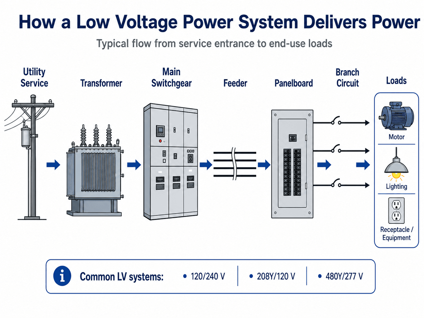
Notice that the system is not just a panel or a breaker. Each stage has a role: transformation, distribution, protection, routing, and safe delivery of power to equipment.
What Is a Low Voltage Power System?
A low voltage power system is the portion of an electrical power system that distributes power at utilization voltages suitable for facility equipment and end-use loads. In many building and industrial contexts, that includes systems such as 120/240 V, 208Y/120 V, 480Y/277 V, and 600 V class distribution. The exact cutoff for “low voltage” depends on the standard, jurisdiction, region, and application.
In power systems engineering, low voltage distribution is often the final major step before electricity reaches useful work. A transformer steps voltage down from a higher distribution level, main distribution equipment organizes and protects feeders, panelboards divide power into branch circuits, and loads convert electrical energy into motion, light, heat, computation, or process output.
Low voltage power systems are different from low voltage controls, data cabling, security wiring, or limited-energy signaling systems. This page focuses on power distribution systems that can carry significant load current and fault current.
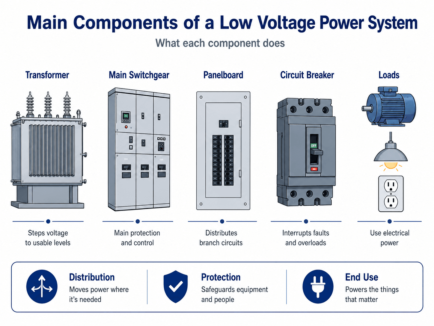
Main Components of a Low Voltage Power System
Low voltage distribution is built from equipment that transforms voltage, routes power, interrupts faults, and delivers energy to loads. The equipment names vary by project, but the functional chain is usually similar: source, transformer or service, main distribution equipment, feeders, panels, protective devices, grounding and bonding, and end-use loads.
| Component | What it does | Engineering check |
|---|---|---|
| Transformer | Steps voltage to a usable level, such as 480Y/277 V or 208Y/120 V. | Review kVA rating, impedance, temperature rise, grounding method, connection type, and available fault current contribution. |
| Main switchgear or switchboard | Receives incoming power and distributes it to large feeders or downstream equipment. | Check voltage rating, bus rating, short-circuit rating, interrupting rating, metering, and maintenance access. |
| Feeder | Carries power from service equipment or main distribution equipment to panels, transformers, motor control centers, or large loads. | Verify ampacity, insulation rating, voltage drop, routing, conduit fill, terminations, and protection at the source. |
| Panelboard | Divides power into branch circuits for lighting, receptacles, small equipment, and local loads. | Review panel schedule, phase balance, spare capacity, breaker compatibility, and circuit labeling. |
| Circuit breaker or fuse | Interrupts overloads, short circuits, and some ground-fault conditions depending on the device and system design. | Compare continuous rating, trip characteristics, interrupting rating, and coordination with upstream and downstream devices. |
| Grounding and bonding system | Stabilizes system voltage and creates an effective fault-current return path so protective devices can operate. | Confirm bonding jumpers, equipment grounding conductors, neutral-ground relationship, enclosure bonding, and continuity of the fault path. |
| Loads | Use delivered electrical power for motors, lighting, HVAC, receptacles, process equipment, controls, and electronics. | Check running current, starting current, harmonics, duty cycle, voltage tolerance, and maintenance requirements. |
How Low Voltage Power Systems Work
During normal operation, current flows from the source through conductors, busbars, breakers, feeders, and branch circuits to the connected loads. During an abnormal condition, such as an overload or short circuit, the protective device closest to the fault should open before upstream equipment trips. The reliability goal is to isolate the failed part without unnecessarily shutting down the rest of the facility.
Source to transformer
Many low voltage systems begin at a utility service transformer or an internal facility transformer. The transformer sets the utilization voltage and strongly affects available fault current. A larger transformer or lower transformer impedance can make the low voltage side capable of delivering very high short-circuit current.
Main distribution to feeders
Main switchgear, switchboards, or distribution panels organize outgoing feeders. This is where engineers check bus ratings, main overcurrent protection, metering, short-circuit ratings, working clearances, and whether the system can be safely isolated for maintenance.
Panelboards to branch circuits
Panelboards split power into branch circuits that serve lighting, receptacles, small equipment, HVAC loads, controls, and process equipment. Branch circuit design must match the load, conductor ampacity, breaker rating, voltage drop, grounding path, and physical installation conditions.
Low Voltage vs Medium Voltage vs High Voltage
Voltage-class names are useful, but they are not always universal. A building engineer, utility engineer, equipment manufacturer, and code reviewer may use slightly different cutoffs. For learning and design review, it is best to understand the role each voltage level plays in the power system.
| Voltage class | Typical role | Common examples | Main engineering concern |
|---|---|---|---|
| Low voltage | Final distribution to usable facility loads. | 120/240 V, 208Y/120 V, 480Y/277 V, 600 V class systems. | Load current, fault current, voltage drop, protection, grounding, bonding, and equipment ratings. |
| Medium voltage | Facility or utility distribution before final step-down transformation. | 4.16 kV, 12.47 kV, 13.8 kV, and other distribution voltages. | Switching, insulation, relaying, transformer selection, arc flash, and safe isolation. |
| High voltage | Bulk power movement, transmission, and substation-level delivery. | Transmission-level voltages used by utilities and large grid systems. | Insulation coordination, system stability, clearances, substations, and protective relaying. |
Do not assume the label “low voltage” defines the design rules by itself. Always identify the actual voltage, phase arrangement, source, grounding method, available fault current, and equipment rating basis.
Common Low Voltage System Types and Voltages
Low voltage systems can be single-phase, three-phase, AC, DC, grounded, ungrounded, or impedance-grounded depending on the application. The system type affects conductor arrangement, neutral loading, protective device behavior, grounding, fault clearing, and the kinds of loads the system can serve.
| System type | Where it is used | Key engineering point |
|---|---|---|
| 120/240 V single-phase | Residential and light commercial services, receptacles, appliances, and small panels. | Two hot legs and a neutral serve both 120 V and 240 V loads; load balance and neutral connections matter. |
| 208Y/120 V three-phase | Commercial buildings with receptacles, small three-phase loads, lighting, office equipment, and mechanical systems. | Supports 120 V line-to-neutral loads and 208 V three-phase loads, but motor torque and voltage drop should be reviewed. |
| 480Y/277 V three-phase | Commercial and industrial distribution, large motors, HVAC equipment, pumps, and 277 V lighting. | Reduces current for a given power level but increases the importance of fault-current ratings, PPE boundaries, and maintenance practices. |
| High-leg delta | Older or specialized commercial and industrial installations. | The high leg must be clearly identified and not accidentally connected to line-to-neutral loads that are not rated for it. |
| Corner-grounded delta | Some industrial systems and specialized equipment arrangements. | Ground-fault behavior, overcurrent protection, and equipment marking differ from common wye systems. |
| DC low voltage systems | Solar PV equipment, batteries, UPS systems, telecom power, control panels, and converter-based systems. | DC faults can be harder to interrupt because current does not naturally cross zero, so DC-rated disconnects, fuses, breakers, and equipment markings matter. |
AC and DC low voltage systems
AC low voltage systems are common in building distribution, motors, lighting, receptacles, and HVAC equipment. DC low voltage systems appear in batteries, solar PV equipment, UPS systems, telecom power, and control circuits. DC equipment must be evaluated with DC-rated devices because arc behavior, polarity, grounding, and interruption are different from AC systems.
Low Voltage Power System Design Workflow
A strong low voltage design workflow starts with the source and ends with the load, but it also traces the fault-current return path back to the source. This prevents a common mistake: sizing equipment for normal current while missing short-circuit ratings, bonding continuity, voltage drop, or maintenance access.
Define the system voltage and source, calculate demand load, select the service or transformer size, lay out main distribution equipment, size feeders and branch circuits, check voltage drop, calculate available fault current, select rated protective devices, review coordination, verify grounding and bonding, then update the one-line diagram and panel schedules.
| Step | What the engineer checks | Why it matters |
|---|---|---|
| 1. Define voltage and configuration | Confirm whether the system is 120/240 V, 208Y/120 V, 480Y/277 V, 600 V class, DC, wye, delta, or another arrangement. | The voltage and configuration control equipment ratings, grounding, conductor count, load compatibility, and protection strategy. |
| 2. Calculate connected and demand load | Separate nameplate load from expected operating demand, load diversity, duty cycle, and future expansion. | Oversizing wastes cost and space; undersizing creates overheating, voltage drop, nuisance trips, and limited spare capacity. |
| 3. Select service or transformer capacity | Review kVA, voltage, impedance, cooling, grounding, and utility or facility source limitations. | The source controls capacity, short-circuit current, voltage regulation, and future expansion margin. |
| 4. Lay out distribution equipment | Place switchboards, switchgear, panelboards, motor control centers, disconnects, and distribution panels in a logical sequence. | Good layout improves operation, maintenance, isolation, and safe access during normal and emergency work. |
| 5. Size feeders and branch circuits | Check ampacity, insulation, temperature ratings, conductor material, raceway fill, length, and installation environment. | Conductors must carry load safely under real installation conditions, not just ideal table conditions. |
| 6. Check voltage drop | Review long feeders, remote panels, high-current equipment, motor starting, and sensitive loads. | Voltage drop can cause poor equipment performance even when the conductor is thermally adequate. |
| 7. Calculate available fault current | Use source data, transformer impedance, conductor impedance, and system configuration to estimate fault current at each equipment location. | Equipment must have adequate interrupting rating, short-circuit current rating, and withstand capability. |
| 8. Review protective device coordination | Compare downstream and upstream breaker or fuse behavior for overloads, short circuits, and ground faults. | Coordination limits outage areas and helps the closest device clear the fault when practical. |
| 9. Verify grounding and bonding | Trace equipment grounding conductors, bonding jumpers, metallic raceways, neutral-ground bonds, and enclosure continuity. | A low-impedance return path helps protective devices trip quickly during faults. |
| 10. Check documentation and maintainability | Confirm panel schedules, one-line diagrams, working clearances, labels, spare breakers, and access paths. | A system that cannot be identified, accessed, or isolated safely becomes difficult and risky to maintain. |
What Controls Low Voltage System Design?
Low voltage design is controlled by more than the connected load nameplate. Engineers review how much load will operate at the same time, how far power must travel, how much fault current is available, how protection will coordinate, and whether the installed equipment can be safely operated and maintained.
| Design control | Why it matters | Engineering implication |
|---|---|---|
| Calculated load and demand | Installed load is not always the same as realistic operating demand. | Service, transformer, feeder, and panel sizes should reflect applicable demand factors and expected operation. |
| Conductor ampacity | Conductors must carry current without overheating under installed conditions. | Temperature rating, bundling, conduit fill, ambient temperature, insulation type, and termination ratings can all affect conductor selection. |
| Voltage drop | Long or heavily loaded feeders can deliver voltage below what equipment expects. | Voltage drop can drive conductor upsizing even when ampacity alone appears acceptable. |
| Available fault current | Low voltage equipment may see extremely high short-circuit current close to transformers or service equipment. | Breakers, fuses, switchgear, panelboards, and bus bracing must be rated for the available fault current at their terminals. |
| Protection coordination | The closest protective device should clear the fault when practical. | Trip curves, breaker settings, fuses, instantaneous functions, and ground-fault protection affect outage boundaries. |
| Grounding and bonding | The system must maintain stable references and provide a low-impedance fault path. | Poor bonding can leave enclosures energized and prevent breakers from clearing faults quickly. |
| Physical installation | Equipment has to fit, breathe, be accessed, and be maintained. | Working space, ventilation, clearances, cable bending space, labels, and environmental ratings are design constraints, not afterthoughts. |
What a Low Voltage One-Line Diagram Should Show
A one-line diagram is often the fastest way to understand a low voltage power system. It should show more than boxes and arrows. A useful one-line provides the data needed for load review, short-circuit studies, coordination studies, switching plans, maintenance, and field troubleshooting.
| One-line item | Why it matters | Practical review note |
|---|---|---|
| Transformer kVA and impedance | Controls capacity, voltage behavior, and available fault current. | Missing impedance data weakens short-circuit calculations. |
| System voltage and phase | Defines equipment compatibility and conductor arrangement. | Confirm whether the system is single-phase, three-phase wye, delta, or DC. |
| Main breaker or main fuse rating | Defines the starting point for protection and coordination. | Review continuous rating, trip unit, interrupting rating, and settings if adjustable. |
| Bus rating | Shows how much current equipment can carry continuously. | Do not confuse bus rating with short-circuit rating. |
| AIC or SCCR rating | Shows whether equipment can safely interrupt or withstand fault current. | Compare ratings with available fault current at each equipment location. |
| Feeder size and length | Affects ampacity, voltage drop, and downstream fault current. | Long feeders may need voltage-drop review even when ampacity is acceptable. |
| Grounding method | Controls how the system is referenced and how faults return to the source. | Review neutral-ground relationship, bonding jumpers, and equipment grounding conductors. |
| Panel names and load descriptions | Supports safe switching, maintenance, and troubleshooting. | Field-verify critical loads instead of trusting old labels blindly. |
Voltage Drop, Fault Current, and Protection Checks
Three checks often separate a usable low voltage layout from a weak one: voltage drop during normal operation, short-circuit current during faults, and whether protection devices coordinate well enough to isolate the correct circuit. These checks are connected because conductor impedance, transformer impedance, and device settings all shape system behavior.
Voltage drop
Voltage drop is the reduction in voltage between the source and load while current flows. A simplified form is useful for intuition:
In AC low voltage systems, practical voltage drop depends on current, conductor resistance, conductor reactance, power factor, length, phase arrangement, and load behavior. Long feeders serving motors, rooftop equipment, pumps, or remote panels can require larger conductors than ampacity alone would suggest.
Available fault current
Available fault current is the current the system can deliver into a short circuit at a specific point. It is usually highest near the transformer or service equipment and lower farther downstream because feeder impedance reduces the fault current. Equipment must still be rated for the current available where it is installed.
Selective coordination
Selective coordination means the downstream breaker or fuse clears a downstream fault before an upstream device opens. In low voltage systems, this can be difficult when instantaneous trip functions overlap or when fault current is high enough to push multiple devices into fast trip regions.
A 480 V low voltage system can have much higher fault energy than a casual reader expects. The risk is controlled by equipment ratings, maintenance condition, protective device settings, enclosure construction, grounding, and safe work practices.
Example: Reviewing a 480 V Feeder to a Motor Control Panel
Consider a 480Y/277 V low voltage distribution system feeding a motor control panel from a main switchboard. The design question is not only whether the feeder can carry the expected motor load. The engineer also needs to confirm voltage drop, short-circuit rating, protection, grounding, working clearance, and future maintenance conditions.
Scenario assumptions
The feeder serves a motor control panel with several motors that may start and stop during normal operation. The system is supplied from a nearby transformer through a main switchboard, and the motor control panel is located far enough away that feeder length and voltage drop should be reviewed.
| Review item | Question to ask | Engineering interpretation |
|---|---|---|
| Feeder ampacity | Can the feeder carry the expected motor load under installed conditions? | A conductor that is acceptable in a table may still need adjustment for temperature, grouping, termination rating, or installation method. |
| Voltage drop | Will the motors receive adequate voltage during running and starting? | Motor starting can expose voltage-drop issues that are not obvious from steady-state running current alone. |
| Available fault current | What fault current can reach the motor control panel terminals? | The panel and protective devices must be rated for the available short-circuit current at that location. |
| Breaker or fuse selection | Does the upstream device protect the feeder while allowing expected motor starting? | Overly aggressive trip settings can cause nuisance trips; overly loose settings can weaken protection. |
| Equipment grounding conductor | Is there a continuous low-impedance path from the panel enclosure back to the source? | The bonding and equipment grounding path is essential for fault clearing if a line conductor contacts metal equipment. |
| Field labeling | Can technicians identify the feeder, upstream breaker, panel name, and loads? | Clear labeling reduces unsafe switching, troubleshooting errors, and maintenance delays. |
Engineering meaning
The feeder is acceptable only if the full system works: the conductor carries load safely, voltage at the motors remains usable, the upstream device can interrupt faults, the equipment is rated for available fault current, and the bonding path can return fault current to the source. A low voltage design review is therefore a system review, not a single calculation.
Grounding, Bonding, and Fault Clearing
Grounding and bonding are often discussed together, but they do different jobs. Grounding establishes a system reference and helps stabilize voltage. Bonding connects conductive parts together so a fault on an enclosure has a low-impedance path back to the source. That return path allows enough current to flow for the protective device to trip.
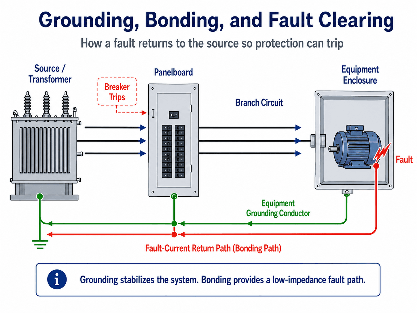
Why the fault path matters
If a line conductor contacts a metal enclosure, the enclosure can become energized. A proper bonding path turns that fault into a high-current event that an overcurrent device can detect. Without a continuous low-impedance path, the fault current may be too low or too unstable to clear quickly.
Grounding is not a substitute for bonding
A grounding electrode alone is not the normal fault-clearing path for a low voltage equipment fault. The effective return path is through bonded metallic paths and equipment grounding conductors back to the source. This is why loose bonding jumpers, painted connections, missing grounding conductors, and damaged raceways can create serious hazards.
Power Quality Issues in Low Voltage Systems
Low voltage systems often serve the loads that create power quality problems. Variable frequency drives, LED drivers, UPS systems, battery chargers, computer power supplies, welders, elevators, and other nonlinear loads can distort current waveforms or create operating conditions that a simple steady-state diagram does not show.
| Power quality issue | Typical source | Why it matters in low voltage systems |
|---|---|---|
| Voltage drop or voltage sag | Long feeders, motor starting, large inrush loads, undersized conductors. | Can cause motor starting problems, dimming lights, control resets, and nuisance equipment trips. |
| Harmonics | VFDs, LED drivers, UPS systems, rectifiers, battery chargers, and computer power supplies. | Can heat transformers and neutrals, distort voltage waveforms, and interfere with sensitive equipment. |
| Phase imbalance | Uneven single-phase loading on a three-phase system. | Can increase neutral current, reduce motor performance, and create uneven conductor heating. |
| Nuisance tripping | Inrush current, harmonics, ground-fault leakage, poor coordination, or marginal breaker settings. | Can interrupt operations even when there is no sustained overload on the circuit. |
| Loose or high-resistance terminations | Aging equipment, vibration, thermal cycling, or poor installation workmanship. | Can cause heat buildup, voltage instability, equipment damage, and fire risk. |
Power quality complaints often show up as intermittent symptoms: lights flicker, drives trip, electronics reset, breakers nuisance trip, or a panel runs warm. These symptoms deserve a system-level review, not just a load-by-load guess.
Where Low Voltage Power Systems Are Used
Low voltage power systems appear anywhere electricity must be distributed safely to usable loads. The engineering details change by building type, equipment type, operating priority, and maintenance environment.
- Residential buildings: 120/240 V split-phase service, panelboards, receptacles, lighting, appliances, HVAC, and small equipment loads.
- Commercial buildings: 208Y/120 V or 480Y/277 V systems for lighting, mechanical equipment, elevators, receptacles, kitchens, data rooms, and tenant panels.
- Industrial facilities: 480 V or 600 V class distribution for motors, pumps, conveyors, process equipment, motor control centers, and maintenance panels.
- Renewable energy sites: inverter outputs, collection panels, auxiliary power panels, battery systems, trackers, communications, and O&M facility loads.
- Data centers and critical facilities: switchboards, UPS systems, power distribution units, redundant feeders, generators, and selective coordination for uptime.
The same one-line concept applies across project types, but the design priority changes. A residence may prioritize simplicity and cost, while a data center may prioritize redundancy, maintainability, coordination, monitoring, and fast recovery after faults.
Low Voltage Power System Design Review Checklist
A low voltage system review should trace the design from source to load and back through the fault-current return path. The goal is to confirm that the system can carry normal load, maintain acceptable voltage, interrupt faults, clear safely, and remain maintainable in the field.
Start with the one-line diagram, confirm the source and transformer data, verify load demand, check equipment ratings, calculate voltage drop and fault current, review protective device coordination, then walk the grounding and bonding path from each enclosure back to the source.
| Review check | What to look for | Why it matters |
|---|---|---|
| One-line diagram matches the field | Service, transformer, switchgear, panelboards, feeders, breakers, and loads are shown with correct names and ratings. | Design studies and maintenance decisions fail quickly when the one-line does not match installed equipment. |
| Transformer data is known | kVA rating, voltage, impedance, grounding method, and connection type are available. | Transformer data controls load capacity, voltage behavior, grounding, and available fault current. |
| Equipment short-circuit ratings are adequate | Panelboards, switchboards, switchgear, breakers, and fuses have ratings above the available fault current. | Underrated equipment may fail violently during a fault instead of safely interrupting or withstanding it. |
| Voltage drop is acceptable | Long feeders, high-current loads, motor circuits, and remote panels are checked under expected operating conditions. | Excessive voltage drop can cause nuisance trips, poor motor starting, dim lighting, overheating, and equipment malfunction. |
| Protection is coordinated where practical | Downstream breakers or fuses clear downstream faults without unnecessary upstream trips. | Good coordination limits outage areas and improves reliability during faults. |
| Grounding and bonding are continuous | Equipment grounding conductors, bonding jumpers, metallic raceways, neutral-ground bonds, and enclosure bonds are properly arranged. | A weak fault path can leave equipment energized or delay breaker operation. |
| Panel schedules are complete | Loads are labeled, spare breakers are identified, phases are balanced, and abandoned circuits are cleaned up. | Clear documentation reduces troubleshooting time and lowers the chance of incorrect switching. |
| Maintenance access is preserved | Working clearances, door swings, ventilation, cable bending space, and safe access routes are not blocked. | Even a well-designed system becomes unsafe if technicians cannot inspect, operate, or maintain it safely. |
Engineering Judgment and Field Reality
Simplified diagrams make low voltage systems look orderly, but field installations often contain old panels, undocumented modifications, overloaded spare circuits, mislabeled breakers, mixed conductor sizes, tight electrical rooms, and equipment added long after the original design. Engineers and technicians must compare drawings, labels, nameplates, and field observations before trusting assumptions.
The most important field habit is to treat the system as an installed network rather than a set of isolated parts. A panel replacement can change available fault current exposure. A transformer upgrade can invalidate downstream ratings. A new large motor can create voltage drop and starting issues. A missing bonding jumper can turn a small insulation fault into a shock hazard.
Low voltage problems often appear as small symptoms: nuisance breaker trips, warm panels, dimming lights, unexplained equipment resets, or confusing labels. Those symptoms can point to deeper issues such as overloaded circuits, loose terminations, poor phase balance, harmonics, or inadequate fault-current documentation.
When This Breaks Down
A simple low voltage system model breaks down when the installed equipment, load behavior, or fault path does not match the assumptions shown on the one-line diagram. This is especially common in older buildings, industrial plants, tenant spaces, and facilities that have grown through many small projects.
- Drawings are outdated: The one-line may not show added panels, replaced breakers, new transformers, temporary feeds, or abandoned circuits.
- Load behavior is not steady: Motor starting, welders, compressors, elevators, HVAC equipment, and nonlinear loads can create voltage dips, harmonics, and nuisance trips.
- Available fault current changed: Utility upgrades, transformer replacements, or parallel sources can increase short-circuit current beyond older equipment ratings.
- Bonding is incomplete: Missing jumpers, poor terminations, nonconductive fittings, corrosion, or damaged raceways can weaken the fault-current return path.
- Protection settings overlap: Upstream and downstream devices may trip together when instantaneous regions overlap or when coordination was never studied.
Common Mistakes and Practical Checks
The most common low voltage mistakes come from treating the system as a collection of parts instead of a coordinated distribution network. A breaker, conductor, panel, transformer, or grounding conductor may look acceptable by itself but still fail as part of the overall system.
| Common mistake | Why it matters | Practical check |
|---|---|---|
| Assuming low voltage means low hazard | Low voltage equipment can still deliver dangerous shock and arc-flash energy. | Review incident energy, working condition, equipment labels, and proper qualified-worker procedures. |
| Checking ampacity but ignoring voltage drop | A conductor can be thermally adequate but still deliver poor voltage at the load. | Check long feeders, motor circuits, rooftop loads, remote panels, and high-current equipment under realistic load. |
| Ignoring available fault current | Panelboards and breakers may be installed where fault current exceeds their ratings. | Compare equipment short-circuit ratings with current fault-current calculations at each equipment location. |
| Trusting panel labels without verification | Incorrect labels can lead to unsafe switching and wasted troubleshooting time. | Field-verify critical circuits, update panel schedules, and remove abandoned or misleading labels. |
| Confusing grounding with bonding | A grounding electrode does not replace the need for a continuous low-impedance bonding path. | Trace the equipment grounding conductor and bonding path back to the source or service bonding point. |
| Ignoring nonlinear loads | VFDs, LED drivers, UPS systems, and electronic power supplies can create harmonics and neutral heating. | Review harmonic sources, transformer heating, neutral loading, and sensitive equipment behavior. |
Do not approve a low voltage modification based only on connected load. A safe review also checks short-circuit rating, voltage drop, grounding and bonding, panel capacity, breaker compatibility, working space, power quality, and documentation.
Codes, Standards, and Practical Design References
Low voltage power systems are controlled by a combination of adopted electrical codes, equipment listings, owner standards, utility requirements, manufacturer instructions, and the authority having jurisdiction. For U.S. building and facility installations, NFPA 70 is the primary electrical installation code framework used to evaluate conductor sizing, overcurrent protection, grounding and bonding, equipment installation, working space, and related safety requirements.
- NFPA 70 National Electrical Code: NFPA 70 National Electrical Code for electrical installations provides the primary U.S. code framework commonly used for safe electrical design and installation in residential, commercial, and industrial settings.
- Project-specific criteria: Utility service requirements, owner standards, equipment listings, local amendments, and AHJ expectations may control final service equipment, conductor, protection, grounding, and working-clearance decisions.
- Engineering use: Engineers typically combine the adopted code, one-line diagrams, load calculations, short-circuit studies, coordination studies, arc-flash studies, and field verification before approving major low voltage equipment changes.
Frequently Asked Questions
A low voltage power system is the final electrical distribution layer that delivers usable power to buildings, equipment, panels, branch circuits, and end-use loads. It commonly includes transformers, switchboards or switchgear, panelboards, feeders, breakers, grounding and bonding paths, and loads such as motors, lighting, receptacles, HVAC equipment, and controls.
No. Low voltage systems can still have serious shock, arc flash, fire, and equipment-damage hazards. A 480 V or 208 V system may have enough available fault current to damage equipment or injure workers if interrupting ratings, grounding, bonding, protection coordination, and working clearances are not handled correctly.
Common low voltage systems include 120/240 V single-phase services, 208Y/120 V three-phase systems, 480Y/277 V three-phase systems, and 600 V class industrial distribution. The exact definition of low voltage depends on the standard, code context, region, and whether the discussion is about building power, controls, telecom, or utility distribution.
Low voltage power systems distribute usable electrical energy to loads such as motors, lighting, receptacles, HVAC equipment, panels, and industrial equipment. Low voltage controls usually refer to signaling, automation, communication, security, instrumentation, or control circuits that carry much lower energy and follow different design priorities.
Common problems include overloaded panels, undersized feeders, excessive voltage drop, loose terminations, poor labeling, missing bonding connections, incorrect breaker ratings, nuisance tripping, harmonics from nonlinear loads, unbalanced phases, heat buildup, and equipment that is not rated for the available fault current.
Summary and Next Steps
Low voltage power systems are the practical distribution layer that connects electrical sources to the loads people actually use. They include transformers, switchgear or switchboards, feeders, panelboards, branch circuits, protective devices, grounding and bonding systems, and connected equipment.
The most important review items are load demand, voltage class, conductor sizing, voltage drop, available fault current, interrupting ratings, protective device coordination, grounding and bonding continuity, labeling, power quality, and maintenance access. A low voltage system is safest when it is reviewed as a complete source-to-load and fault-return network.
Where to go next
Continue your learning path with related Turn2Engineering resources.
-
Power Distribution
Learn how electrical power is routed from supply points to customers, facilities, equipment, and end-use loads.
-
Power Transmission
Understand how higher-voltage systems move bulk power before it is stepped down for distribution.
-
Power Systems Engineering
Explore the broader topic cluster around generation, transmission, distribution, protection, stability, and electrical system equipment.